EP1097799A1 - Bandlegeeinheit zum Auftragen eines Bandes aus Verbundmaterial - Google Patents
Bandlegeeinheit zum Auftragen eines Bandes aus Verbundmaterial Download PDFInfo
- Publication number
- EP1097799A1 EP1097799A1 EP00403089A EP00403089A EP1097799A1 EP 1097799 A1 EP1097799 A1 EP 1097799A1 EP 00403089 A EP00403089 A EP 00403089A EP 00403089 A EP00403089 A EP 00403089A EP 1097799 A1 EP1097799 A1 EP 1097799A1
- Authority
- EP
- European Patent Office
- Prior art keywords
- strip
- composite
- application
- strips
- applying
- Prior art date
- Legal status (The legal status is an assumption and is not a legal conclusion. Google has not performed a legal analysis and makes no representation as to the accuracy of the status listed.)
- Granted
Links
- 239000002131 composite material Substances 0.000 title claims abstract description 32
- 238000000151 deposition Methods 0.000 title 1
- 238000005520 cutting process Methods 0.000 claims abstract description 12
- 230000007246 mechanism Effects 0.000 claims abstract description 12
- 230000009471 action Effects 0.000 claims abstract description 9
- 238000003825 pressing Methods 0.000 claims abstract description 4
- 210000004907 gland Anatomy 0.000 claims description 10
- 238000006073 displacement reaction Methods 0.000 claims description 9
- 238000000034 method Methods 0.000 claims description 9
- 230000008569 process Effects 0.000 claims description 9
- 238000005056 compaction Methods 0.000 claims description 8
- 230000005540 biological transmission Effects 0.000 claims description 6
- 238000007689 inspection Methods 0.000 claims 1
- 239000000969 carrier Substances 0.000 abstract 1
- 238000007596 consolidation process Methods 0.000 abstract 1
- 230000004886 head movement Effects 0.000 abstract 1
- 238000010276 construction Methods 0.000 description 4
- 230000006978 adaptation Effects 0.000 description 2
- 230000015572 biosynthetic process Effects 0.000 description 2
- 230000008878 coupling Effects 0.000 description 2
- 238000010168 coupling process Methods 0.000 description 2
- 238000005859 coupling reaction Methods 0.000 description 2
- 230000002950 deficient Effects 0.000 description 2
- 239000012530 fluid Substances 0.000 description 2
- 239000000203 mixture Substances 0.000 description 2
- 241000135309 Processus Species 0.000 description 1
- 239000000470 constituent Substances 0.000 description 1
- 238000012937 correction Methods 0.000 description 1
- 230000007547 defect Effects 0.000 description 1
- 238000010586 diagram Methods 0.000 description 1
- 230000008034 disappearance Effects 0.000 description 1
- 230000000694 effects Effects 0.000 description 1
- 230000005489 elastic deformation Effects 0.000 description 1
- 238000010348 incorporation Methods 0.000 description 1
- 238000009434 installation Methods 0.000 description 1
- 238000004519 manufacturing process Methods 0.000 description 1
- 238000003801 milling Methods 0.000 description 1
- 230000001681 protective effect Effects 0.000 description 1
- 230000009467 reduction Effects 0.000 description 1
Images


Classifications
-
- B—PERFORMING OPERATIONS; TRANSPORTING
- B65—CONVEYING; PACKING; STORING; HANDLING THIN OR FILAMENTARY MATERIAL
- B65H—HANDLING THIN OR FILAMENTARY MATERIAL, e.g. SHEETS, WEBS, CABLES
- B65H16/00—Unwinding, paying-out webs
- B65H16/02—Supporting web roll
- B65H16/04—Supporting web roll cantilever type
-
- B—PERFORMING OPERATIONS; TRANSPORTING
- B65—CONVEYING; PACKING; STORING; HANDLING THIN OR FILAMENTARY MATERIAL
- B65H—HANDLING THIN OR FILAMENTARY MATERIAL, e.g. SHEETS, WEBS, CABLES
- B65H16/00—Unwinding, paying-out webs
-
- B—PERFORMING OPERATIONS; TRANSPORTING
- B29—WORKING OF PLASTICS; WORKING OF SUBSTANCES IN A PLASTIC STATE IN GENERAL
- B29C—SHAPING OR JOINING OF PLASTICS; SHAPING OF MATERIAL IN A PLASTIC STATE, NOT OTHERWISE PROVIDED FOR; AFTER-TREATMENT OF THE SHAPED PRODUCTS, e.g. REPAIRING
- B29C70/00—Shaping composites, i.e. plastics material comprising reinforcements, fillers or preformed parts, e.g. inserts
- B29C70/04—Shaping composites, i.e. plastics material comprising reinforcements, fillers or preformed parts, e.g. inserts comprising reinforcements only, e.g. self-reinforcing plastics
- B29C70/28—Shaping operations therefor
- B29C70/30—Shaping by lay-up, i.e. applying fibres, tape or broadsheet on a mould, former or core; Shaping by spray-up, i.e. spraying of fibres on a mould, former or core
- B29C70/38—Automated lay-up, e.g. using robots, laying filaments according to predetermined patterns
- B29C70/386—Automated tape laying [ATL]
- B29C70/388—Tape placement heads, e.g. component parts, details or accessories
-
- B—PERFORMING OPERATIONS; TRANSPORTING
- B65—CONVEYING; PACKING; STORING; HANDLING THIN OR FILAMENTARY MATERIAL
- B65H—HANDLING THIN OR FILAMENTARY MATERIAL, e.g. SHEETS, WEBS, CABLES
- B65H23/00—Registering, tensioning, smoothing or guiding webs
- B65H23/04—Registering, tensioning, smoothing or guiding webs longitudinally
- B65H23/18—Registering, tensioning, smoothing or guiding webs longitudinally by controlling or regulating the web-advancing mechanism, e.g. mechanism acting on the running web
- B65H23/195—Registering, tensioning, smoothing or guiding webs longitudinally by controlling or regulating the web-advancing mechanism, e.g. mechanism acting on the running web in winding mechanisms or in connection with winding operations
- B65H23/1955—Registering, tensioning, smoothing or guiding webs longitudinally by controlling or regulating the web-advancing mechanism, e.g. mechanism acting on the running web in winding mechanisms or in connection with winding operations and controlling web tension
-
- B—PERFORMING OPERATIONS; TRANSPORTING
- B65—CONVEYING; PACKING; STORING; HANDLING THIN OR FILAMENTARY MATERIAL
- B65H—HANDLING THIN OR FILAMENTARY MATERIAL, e.g. SHEETS, WEBS, CABLES
- B65H37/00—Article or web delivery apparatus incorporating devices for performing specified auxiliary operations
-
- B—PERFORMING OPERATIONS; TRANSPORTING
- B65—CONVEYING; PACKING; STORING; HANDLING THIN OR FILAMENTARY MATERIAL
- B65H—HANDLING THIN OR FILAMENTARY MATERIAL, e.g. SHEETS, WEBS, CABLES
- B65H2301/00—Handling processes for sheets or webs
- B65H2301/40—Type of handling process
- B65H2301/41—Winding, unwinding
- B65H2301/414—Winding
- B65H2301/4143—Performing winding process
- B65H2301/41432—Performing winding process special features of winding process
- B65H2301/414324—Performing winding process special features of winding process involving interleaf web/sheet, e.g. liner
-
- B—PERFORMING OPERATIONS; TRANSPORTING
- B65—CONVEYING; PACKING; STORING; HANDLING THIN OR FILAMENTARY MATERIAL
- B65H—HANDLING THIN OR FILAMENTARY MATERIAL, e.g. SHEETS, WEBS, CABLES
- B65H2301/00—Handling processes for sheets or webs
- B65H2301/50—Auxiliary process performed during handling process
- B65H2301/51—Modifying a characteristic of handled material
- B65H2301/515—Cutting handled material
- B65H2301/5151—Cutting handled material transversally to feeding direction
- B65H2301/51512—Cutting handled material transversally to feeding direction using a cutting member moving linearly in a plane parallel to the surface of the web and along a direction crossing the handled material
-
- B—PERFORMING OPERATIONS; TRANSPORTING
- B65—CONVEYING; PACKING; STORING; HANDLING THIN OR FILAMENTARY MATERIAL
- B65H—HANDLING THIN OR FILAMENTARY MATERIAL, e.g. SHEETS, WEBS, CABLES
- B65H2701/00—Handled material; Storage means
- B65H2701/10—Handled articles or webs
- B65H2701/17—Nature of material
- B65H2701/172—Composite material
Definitions
- the present invention relates to a head for applying strips laminar of what is called a composite, with which, and by superposition compact from which we form laminated pieces, like panels, which we used in the aeronautical, naval industries etc.
- These wrapping heads include compacting elements which are those which press on the strip to be applied, by applying pressure on the latter, to that it attaches to the upper layer of the part being formed, to achieve the compacting by making the incorporation as uniform as possible tape on the surface of the corresponding panel, to prevent it from happening air bubbles in the layer formed, since for certain applications such as those of the aeronautical sector, such bubbles would render the panel which would contain.
- the compacting element adapts to any bends and irregularities that the panel present in its surface and in addition, the compacting element pushes on the belt being applied with adequate force.
- Tubular conduits are common to all parts of the same element compactor and have sufficient rigidity to hold the different parts in the stable alignment position, next to each other but, at the same time, they are flexible, so that if you press on any of the parts externally, it produces a displacement of the latter by elastic deformation of the conduits tubular, which absorb said displacement. At the disappearance of the thrust outside on the moved part, the fluid under pressure from inside the conduits tubular makes it return to the initial position, the part then returning in alignment with the others.
- each compactor element defines a leading edge which adapts to the curvatures and irregularities of the panel that is formed with the strips in progress application, thus achieving uniform compaction of the entire surface.
- This head object of the invention has the particularity that the compaction means consist of a discharge element and an element of pressure, which act independently and successively on each zone application, the two elements being able to be toggled between respective positions of work and removal, so that the gland first performs the application of the band by adapting to the corresponding surface, having for this purpose a construction deformable depending on the surface; while the pressure element then enters action by compressing the strip applied with force on the application surface.
- the compaction means consist of a discharge element and an element of pressure, which act independently and successively on each zone application, the two elements being able to be toggled between respective positions of work and removal, so that the gland first performs the application of the band by adapting to the corresponding surface, having for this purpose a construction deformable depending on the surface; while the pressure element then enters action by compressing the strip applied with force on the application surface.
- perfect compaction of the strips is obtained on the application surface.
- the proposed head further includes a centering and alignment device for the strip with which we avoid the errors to which the misalignment of the strip gives that accumulate during the application process.
- the reel holder which carries the strip conveyor is movable as a whole in the axial direction, thereby allowing to adjust the situation of the carriage for its centering in relation to the alignment of the application; however, on the path from the tape to the application area, conductive guides are arranged, which are adjustable in width for adaptation to the band used and in turn, adjustable in position for centering by report to the alignment of the application.
- cutting means with which the cut the strip of composite as necessary so that it comes off completely safety, respecting the paper backing sheet so that it does not break and that it can be collected without interruption.
- Said cutting means are constituted by two cutting mechanisms, which include rotary actuation by motor, displacement actuation longitudinal by screw and an actuation of displacement in height by cylinders, in allowing cuts to be made along any path and with a total cutting depth of the composite strip, up to the support sheet made of paper without it being affected by a risk of rupture.
- the movements of rotation and tilting of the head used for the wrapping processes are controlled with double pinion mechanisms of attack on a receiving crown, by means of which a precision is obtained total, without play in the inversion of the movement.
- the speed of the tape conveyance to the application area is controlled by means of a transfer encoder roller by means of which an order is made of the belt advance actuation, to maintain a constant speed of arrival to the application area, remaining independent of the variables related to the depletion of the supply coil.
- the present invention relates to a wrapper head, of the type that used for the application of strips of composite in the formation of laminated parts or panels by overlapping and compacting the strips.
- These heads include a spool holder (1) in which a spool is mounted (2) which carries the strip (3) to be applied, said strip (3) being led towards the area of application where pressure means which bring about the compaction of the strip of composite (3.1, Figures 11 to 14) on the forming surface, while the corresponding paper support sheet (3.2) is conducted to be wound on a take-up reel (4) arranged on a respective reel holder (5).
- the means provided for compacting comprise a discharge element (6) and a pressure element (7), which are arranged so independent on respective supports (8 and 9), as seen in Figure 10.
- the gland (6) consists of an element which forms a front actuator flexible, allowing adaptation to the application surface of the composite (3.1), in a way that allows to absorb the irregularities of said surface, by pressing evenly across the entire line of the application.
- Said gland (6) can be tilted with its support (8) by means of cylinders (10), with the possibility of pivoting between a working position on the application area and an inoperative position in a retracted position relative to said area of application.
- the pressure element (7) is formed on its side by a rubber roller which is also mounted so that it can be tilted, being able to pivot by means of cylinders (11) between a working position on the application area and a position inoperative when retracted from said area of application, while at by means of other cylinders (12), a strong pressure can be produced from this roller on the application area, in the working position.
- the composite strip (3.1) is pressed on the surface corresponding by the gland (6), as shown in Figure 11, the pressure element (7) remaining in the inoperative position.
- the pressure element (7) is brought in, by means of the cylinders (12), to exert a strong pressure on the application area, as shown in Figure 14, thus generating perfect compaction of the composite strip (3.1) on the surface corresponding.
- the aforementioned compacting process could also be carried out with two identical elements (6) and (7), but arranged so that one exerts a pressure of laying the composite strip (3.1) and the other exerts a stronger pressure in order to make compaction effective.
- Guiding the strip (3) from the supply reel (2) to the area application is carried out by passing on guides (13) and (14), which are equipped a pressurized air supply, which creates an air cushion on which the strip (3) leans in its sliding, thus avoiding friction.
- Said guides (13) and (14) are formed by a set of sectors which realize a composition adjustable in width, which makes it possible to perfectly adjust each of the guides (13) and (14) to the width of the strip (3) used in a given case; each guides (13) and (14) above having for this an actuator (15, Figure 5) which allows to move the respective constituent assembly, by modifying the width, by approximation or simultaneous removal of the corresponding extreme parts by compared to the center line.
- These guides (13) and (14) also have, as can be seen in FIG. (6) which relates to the guide (13), stops (16) and (16.1) which serve as lateral edges for guiding the strip (3), said stops (16) and (16.1) determining two widths of guidance, for example for strips (3) of the order of 150 millimeters in width and for strips (3) 300 millimeters wide; in each of these ranges, the exact adjustment to the concrete width of the strip (3) used is effected by adjusting the the width by means of the actuator (15) in each case.
- the stops (16) which give the further guide range large width are provided fixed in the mobile end parts of the composition corresponding guides (13) and (14); while the stops (16.1) which give the range of smaller width are provided removable, so it is enough to remove these stops (16.1) to establish in each case the corresponding guide width for the band (3) that we will use.
- the aforementioned guides (13) and (14) are provided with an actuator respective (17) by means of which each of them can be moved en bloc to the sides, in thus being able to adjust the position to ensure perfect centering with respect to alignment of the tape application (3), in order to avoid errors that any deviation alignment would result.
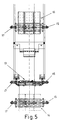
- the reel holder (1) on which is mounted the reel (2) which carries the strip (3) to to apply includes shells (18) which are movable in the radial direction for secure the coil (2) during assembly, or to leave this attachment free for disassembly, this radial movement of the shells (18) occurring by axial displacement of a central axis (19) provided with conical grooves (20), with which cooperate supports (21) of the aforementioned shells (18), as observed on the figure 4.
- This displacement of the central axis (19) is effected by means of an actuator (22) which, depending on the direction of rotation, activates the movement in one direction or the other.
- the reel holder (5) receiving the paper support strip (3.2) comprises: in turn a central axis (23) which can be moved by means of an actuator (24) and which has conical grooves with which the shell supports cooperate corresponding (25) movable in the radial direction, by means of which the fixing of the corresponding reel (4) for receiving the paper strip (3.2).
- the reel holder (1) further comprises an actuator (26) by means of which can move the whole block of said spool holder (1) in the axial direction, allowing thus achieving perfect centering of the strip (3) relative to the proper alignment.
- This adjustment of the centered positioning of the strip (3) with the actuator (26) of the spool holder (1), as well as the adjustment of the centering in this same direction, by means of the actuators (17) of the guides (13) and (14), can be manual, but it can also be produced by a automatic control actuation by means of an installation fitted with appropriate means for this.
- cutting means In the area in which the strip (3) flows from the supply reel (2) towards the application area are arranged cutting means with which the upper composite layer (3.1) of the strip (3) is cut, according to this that was intended for the application.
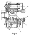
- the actuation of said cutting means is fully automatic, its operation being controlled from a box of control (27) arranged on the support (28) of the head.
- These cutting means are constituted by two knife-holder mechanisms (29) and (30), which are arranged, according to FIGS. 7, 8 and 9, in an assembly comprising longitudinal displacement on respective screws (31), and actuation by means corresponding actuators (32), and can in turn be moved vertically on guides (33) corresponding and actuated by means of actuating cylinders respective (34).
- the rotation of said mechanisms (29) and (30) for the actuations of cut, is activated by corresponding motors (35), which activate the rotary movement of the knife axis by means of a pinion transmission and rack.
- the aforementioned mechanisms (29) and (30) allow cuts to be made with absolute precision and in a any trajectory, completely cutting through the upper layer of the composite (3.1) in the cuts so that the scraps to be removed come off easily and without significantly affect the paper support strip (3.2) so that it does not does not break and remains whole downstream of the application area to be collected on the coil (4).
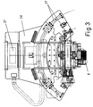
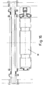
- the head is arranged with rotary mounting of the support (28) with respect to a vertical axis, by actuation by means of a transmission (36), and by tilting mounting on its own support (28), by coupling the transmission on a respective crown (37), according to Figures 1, 2 and 3.
- the transmission (36) of the rotary actuation and the coupling of the transmission on the crown (37) provided for tilting actuation takes place at by means of a set of two drive pinions, one of the pinions the actuation in action in one direction and the other the actuation in the other direction, so that we obtain a total precision of movements, without play in the inversion of movements.
- the speed of the strip (3) in its movement from the reel (2) supply to the application area is controlled by an encoder roller (38) transfer, visible in Figures 1 and 2 and shown in Figure 16, which achieves, by through the appropriate means, an actuation control check conveyor belt drive (3), making the necessary corrections for keep the speed of said strip (3) constant when it arrives at the application area, compensating for variations in said speed as the reduction in diameter and volume of the supply coil (2) tend to cause as a result of consumption, so that the application process on work surfaces is completely uniform.
Landscapes
- Engineering & Computer Science (AREA)
- Robotics (AREA)
- Chemical & Material Sciences (AREA)
- Composite Materials (AREA)
- Mechanical Engineering (AREA)
- Making Paper Articles (AREA)
- Reinforced Plastic Materials (AREA)
- Adhesives Or Adhesive Processes (AREA)
- Winding Of Webs (AREA)
Applications Claiming Priority (2)
| Application Number | Priority Date | Filing Date | Title |
|---|---|---|---|
| ES009902440A ES2186458B1 (es) | 1999-11-08 | 1999-11-08 | Cabezal encintador para la aplicacion de bandas de composite. |
| ES9902440 | 1999-11-08 |
Publications (2)
| Publication Number | Publication Date |
|---|---|
| EP1097799A1 true EP1097799A1 (de) | 2001-05-09 |
| EP1097799B1 EP1097799B1 (de) | 2004-03-31 |
Family
ID=8310502
Family Applications (1)
| Application Number | Title | Priority Date | Filing Date |
|---|---|---|---|
| EP00403089A Expired - Lifetime EP1097799B1 (de) | 1999-11-08 | 2000-11-08 | Bandlegeeinheit zum Auftragen eines Bandes aus Verbundmaterial |
Country Status (3)
| Country | Link |
|---|---|
| EP (1) | EP1097799B1 (de) |
| DE (1) | DE60009421T2 (de) |
| ES (1) | ES2186458B1 (de) |
Cited By (7)
| Publication number | Priority date | Publication date | Assignee | Title |
|---|---|---|---|---|
| CN102328858A (zh) * | 2010-07-12 | 2012-01-25 | 南通瑞和船舶配件有限公司 | 限位压轮 |
| CN103722752A (zh) * | 2013-12-31 | 2014-04-16 | 中国航空工业集团公司北京航空制造工程研究所 | 具有压力检测装置的复合材料预浸带铺放机构 |
| DE102014016404A1 (de) | 2014-11-05 | 2016-05-12 | Tekon D.O.O. | Bandverlegemaschine |
| WO2018020162A1 (fr) * | 2016-07-27 | 2018-02-01 | Irt Jules Verne | Dispositif et procédé pour la fabrication d'une préforme fibreuse |
| CN108621443A (zh) * | 2018-04-27 | 2018-10-09 | 武汉大学 | 一种基于复合材料铺带头的输带装置 |
| JP2023521240A (ja) * | 2020-04-15 | 2023-05-23 | エメ. トレース ディセニョス インダストリアレス, エセ.ア.ウ. | 複合テープのアプリケーターヘッド |
| CN119460845A (zh) * | 2024-11-20 | 2025-02-18 | 杭州艾美依航空制造装备有限公司 | 一种适用于复合材料全自动铺带设备的带料导向装置及方法 |
Families Citing this family (1)
| Publication number | Priority date | Publication date | Assignee | Title |
|---|---|---|---|---|
| ES2899313B2 (es) * | 2020-04-15 | 2023-09-25 | M Torres Disenos Ind S A Unipersonal | Cabezal encintador de bandas de composite con medios de recogida |
Citations (8)
| Publication number | Priority date | Publication date | Assignee | Title |
|---|---|---|---|---|
| EP0144927A2 (de) * | 1983-12-05 | 1985-06-19 | Cincinnati Milacron Inc. | Verfahren und Vorrichtung zum Aufbringen von Bändern auf eine Form |
| US4591402A (en) * | 1981-06-22 | 1986-05-27 | Ltv Aerospace And Defense Company | Apparatus and method for manufacturing composite structures |
| US4696707A (en) * | 1987-08-18 | 1987-09-29 | The Ingersoll Milling Machine Company | Composite tape placement apparatus with natural path generation means |
| EP0333010A1 (de) * | 1988-03-15 | 1989-09-20 | Cincinnati Milacron Inc. | Bandlegevorrichtung und dazugehörige Regelung |
| EP0644042A1 (de) * | 1993-05-27 | 1995-03-22 | Cincinnati Milacron Inc. | Auflegevorrichtung für Verbundwerkstoffbänder |
| FR2713213A1 (fr) * | 1993-11-30 | 1995-06-09 | Torres Martinez M | Tête pour l'application de bandes de composite. |
| ES2114413A1 (es) * | 1994-10-07 | 1998-05-16 | Torres Martinez M | Cabezal para la aplicacion de bandas de composite. |
| FR2756510A1 (fr) * | 1996-12-03 | 1998-06-05 | Aerospatiale | Tete de drapage, pour la fabrication de plaques en materiau composite |
Family Cites Families (2)
| Publication number | Priority date | Publication date | Assignee | Title |
|---|---|---|---|---|
| US4627886A (en) * | 1985-05-30 | 1986-12-09 | Cincinnati Milacron Inc. | Composite tape laying machine with pivoting presser member |
| JPH0741672B2 (ja) * | 1988-05-07 | 1995-05-10 | 新日本工機株式会社 | テープの自動貼付装置 |
-
1999
- 1999-11-08 ES ES009902440A patent/ES2186458B1/es not_active Expired - Fee Related
-
2000
- 2000-11-08 EP EP00403089A patent/EP1097799B1/de not_active Expired - Lifetime
- 2000-11-08 DE DE60009421T patent/DE60009421T2/de not_active Expired - Lifetime
Patent Citations (8)
| Publication number | Priority date | Publication date | Assignee | Title |
|---|---|---|---|---|
| US4591402A (en) * | 1981-06-22 | 1986-05-27 | Ltv Aerospace And Defense Company | Apparatus and method for manufacturing composite structures |
| EP0144927A2 (de) * | 1983-12-05 | 1985-06-19 | Cincinnati Milacron Inc. | Verfahren und Vorrichtung zum Aufbringen von Bändern auf eine Form |
| US4696707A (en) * | 1987-08-18 | 1987-09-29 | The Ingersoll Milling Machine Company | Composite tape placement apparatus with natural path generation means |
| EP0333010A1 (de) * | 1988-03-15 | 1989-09-20 | Cincinnati Milacron Inc. | Bandlegevorrichtung und dazugehörige Regelung |
| EP0644042A1 (de) * | 1993-05-27 | 1995-03-22 | Cincinnati Milacron Inc. | Auflegevorrichtung für Verbundwerkstoffbänder |
| FR2713213A1 (fr) * | 1993-11-30 | 1995-06-09 | Torres Martinez M | Tête pour l'application de bandes de composite. |
| ES2114413A1 (es) * | 1994-10-07 | 1998-05-16 | Torres Martinez M | Cabezal para la aplicacion de bandas de composite. |
| FR2756510A1 (fr) * | 1996-12-03 | 1998-06-05 | Aerospatiale | Tete de drapage, pour la fabrication de plaques en materiau composite |
Cited By (10)
| Publication number | Priority date | Publication date | Assignee | Title |
|---|---|---|---|---|
| CN102328858A (zh) * | 2010-07-12 | 2012-01-25 | 南通瑞和船舶配件有限公司 | 限位压轮 |
| CN103722752A (zh) * | 2013-12-31 | 2014-04-16 | 中国航空工业集团公司北京航空制造工程研究所 | 具有压力检测装置的复合材料预浸带铺放机构 |
| CN103722752B (zh) * | 2013-12-31 | 2016-03-09 | 中国航空工业集团公司北京航空制造工程研究所 | 具有压力检测装置的复合材料预浸带铺放机构 |
| DE102014016404A1 (de) | 2014-11-05 | 2016-05-12 | Tekon D.O.O. | Bandverlegemaschine |
| DE102014016404B4 (de) | 2014-11-05 | 2019-05-29 | Tekon D.O.O. | Bandverlegemaschine |
| WO2018020162A1 (fr) * | 2016-07-27 | 2018-02-01 | Irt Jules Verne | Dispositif et procédé pour la fabrication d'une préforme fibreuse |
| FR3054476A1 (fr) * | 2016-07-27 | 2018-02-02 | Institut De Recherche Technologique Jules Verne | Dispositif et procede pour la fabrication d'une preforme fibreuse |
| CN108621443A (zh) * | 2018-04-27 | 2018-10-09 | 武汉大学 | 一种基于复合材料铺带头的输带装置 |
| JP2023521240A (ja) * | 2020-04-15 | 2023-05-23 | エメ. トレース ディセニョス インダストリアレス, エセ.ア.ウ. | 複合テープのアプリケーターヘッド |
| CN119460845A (zh) * | 2024-11-20 | 2025-02-18 | 杭州艾美依航空制造装备有限公司 | 一种适用于复合材料全自动铺带设备的带料导向装置及方法 |
Also Published As
| Publication number | Publication date |
|---|---|
| ES2186458B1 (es) | 2003-12-16 |
| EP1097799B1 (de) | 2004-03-31 |
| DE60009421D1 (de) | 2004-05-06 |
| DE60009421T2 (de) | 2005-03-24 |
| ES2186458A1 (es) | 2003-05-01 |
Similar Documents
| Publication | Publication Date | Title |
|---|---|---|
| EP2339055B1 (de) | Kreisförmige Nadelmaschine wobei einer Faserstoffbahn durch ein Förderband und eine vertikale Rutsche zugeführt wird | |
| EP2177292B1 (de) | Vorrichtung zum Richten und Zuführen von einem halbstarren Materialstreifen in eine Maschine | |
| FR2733450A1 (fr) | Appareil de fendage de feuille | |
| WO2007012739A1 (fr) | Dispositif de coupe longitudinale d'une laize de materiau defilant en continu pour former une bande a profil longitudinal variable | |
| FR2840844A1 (fr) | Disque couper a plongee rotative avec contre-partie rainuree de style a griffe | |
| FR2676427A1 (fr) | Procede et dispositif de bobinage d'une bande de film. | |
| EP2964435A1 (de) | Verfahren zur einstellung des radialspaltes zwischen zwei werkzeugen, anordnung zum umformen eines trägers, kassette, einheit und damit ausgestattete maschine | |
| FR2614601A1 (fr) | Unite de formage reglable pour machines a emballer pour emballages du type emballage continu et analogues et procede pour son reglage | |
| EP1097799B1 (de) | Bandlegeeinheit zum Auftragen eines Bandes aus Verbundmaterial | |
| FR2783191A1 (fr) | Coupe automatique de pieces dans une matiere en feuille | |
| FR2530522A1 (fr) | Dispositif pour l'affutage d'un disque de coupe, notamment d'une machine de tronconnage de rouleaux de papier | |
| FR2533488A1 (fr) | Machine automatique de refendage et de rainurage, notamment pour la fabrication de feuilles en carton ondule | |
| EP0125175B1 (de) | Vorrichtung zum Schneiden von ununterbrochen hergestellten Röhren aus Pappe | |
| EP0620088B1 (de) | Papierschneidvorrichtung | |
| FR2921858A1 (fr) | Tete d'application pour ruban en fibres | |
| FR2513608A1 (fr) | Appareil de manutention de feuilles minces de materiau | |
| FR2915704A1 (fr) | Tete de drapage de composite avec dispositif escamotable de separation de preimpregne de son ruban de support. | |
| EP0707527B1 (de) | Schneidmaschine ausgerüstet mit einem rotierenden rundschneidmesser zum schneiden eines biegsamen materials in form eines einzelnen blattes oder eines kleinen blattstapels, sowie verfahren zur einstellung einer solchen maschine | |
| FR2713213A1 (fr) | Tête pour l'application de bandes de composite. | |
| FR2642004A1 (fr) | Imprimante thermique grande largeur | |
| FR2934807A1 (fr) | Tete de drapage de composite avec dispositif en secteur escamotable de separation de preimpregne de son ruban de support. | |
| EP0266290B1 (de) | Verfahren und Vorrichtung zum Zuführen an einer Schneidvorrichtung | |
| FR2626209A1 (fr) | Machine de decoupe de matiere en bande par jets fluides haute pression | |
| EP1749603A1 (de) | Vorrichtung zum Längsteilen von dünnen Bändern | |
| FR2489204A1 (fr) | Machine a refendre notamment les cuirs et peaux, les produits textiles non tisses, les caoutchoucs, les matieres plastiques en plaques ou en rouleaux |
Legal Events
| Date | Code | Title | Description |
|---|---|---|---|
| PUAI | Public reference made under article 153(3) epc to a published international application that has entered the european phase |
Free format text: ORIGINAL CODE: 0009012 |
|
| AK | Designated contracting states |
Kind code of ref document: A1 Designated state(s): DE FR GB IT |
|
| AX | Request for extension of the european patent |
Free format text: AL;LT;LV;MK;RO;SI |
|
| 17P | Request for examination filed |
Effective date: 20011001 |
|
| AKX | Designation fees paid |
Free format text: DE FR GB IT |
|
| 17Q | First examination report despatched |
Effective date: 20020502 |
|
| GRAP | Despatch of communication of intention to grant a patent |
Free format text: ORIGINAL CODE: EPIDOSNIGR1 |
|
| GRAS | Grant fee paid |
Free format text: ORIGINAL CODE: EPIDOSNIGR3 |
|
| GRAA | (expected) grant |
Free format text: ORIGINAL CODE: 0009210 |
|
| AK | Designated contracting states |
Kind code of ref document: B1 Designated state(s): DE FR GB IT |
|
| PG25 | Lapsed in a contracting state [announced via postgrant information from national office to epo] |
Ref country code: GB Free format text: LAPSE BECAUSE OF FAILURE TO SUBMIT A TRANSLATION OF THE DESCRIPTION OR TO PAY THE FEE WITHIN THE PRESCRIBED TIME-LIMIT Effective date: 20040331 |
|
| REG | Reference to a national code |
Ref country code: GB Ref legal event code: FG4D Free format text: NOT ENGLISH |
|
| REF | Corresponds to: |
Ref document number: 60009421 Country of ref document: DE Date of ref document: 20040506 Kind code of ref document: P |
|
| GBT | Gb: translation of ep patent filed (gb section 77(6)(a)/1977) |
Effective date: 20040910 |
|
| PLBE | No opposition filed within time limit |
Free format text: ORIGINAL CODE: 0009261 |
|
| STAA | Information on the status of an ep patent application or granted ep patent |
Free format text: STATUS: NO OPPOSITION FILED WITHIN TIME LIMIT |
|
| 26N | No opposition filed |
Effective date: 20050104 |
|
| PGFP | Annual fee paid to national office [announced via postgrant information from national office to epo] |
Ref country code: DE Payment date: 20131120 Year of fee payment: 14 Ref country code: FR Payment date: 20131108 Year of fee payment: 14 Ref country code: GB Payment date: 20131105 Year of fee payment: 14 |
|
| PGFP | Annual fee paid to national office [announced via postgrant information from national office to epo] |
Ref country code: IT Payment date: 20131121 Year of fee payment: 14 |
|
| REG | Reference to a national code |
Ref country code: DE Ref legal event code: R119 Ref document number: 60009421 Country of ref document: DE |
|
| GBPC | Gb: european patent ceased through non-payment of renewal fee |
Effective date: 20141108 |
|
| REG | Reference to a national code |
Ref country code: FR Ref legal event code: ST Effective date: 20150731 |
|
| PG25 | Lapsed in a contracting state [announced via postgrant information from national office to epo] |
Ref country code: DE Free format text: LAPSE BECAUSE OF NON-PAYMENT OF DUE FEES Effective date: 20150602 Ref country code: GB Free format text: LAPSE BECAUSE OF NON-PAYMENT OF DUE FEES Effective date: 20141108 |
|
| PG25 | Lapsed in a contracting state [announced via postgrant information from national office to epo] |
Ref country code: FR Free format text: LAPSE BECAUSE OF NON-PAYMENT OF DUE FEES Effective date: 20141201 |
|
| PG25 | Lapsed in a contracting state [announced via postgrant information from national office to epo] |
Ref country code: IT Free format text: LAPSE BECAUSE OF NON-PAYMENT OF DUE FEES Effective date: 20141108 |