EP1099604A2 - "Horn actuating device for a motor-vehicle steering wheel" - Google Patents
"Horn actuating device for a motor-vehicle steering wheel" Download PDFInfo
- Publication number
- EP1099604A2 EP1099604A2 EP00830633A EP00830633A EP1099604A2 EP 1099604 A2 EP1099604 A2 EP 1099604A2 EP 00830633 A EP00830633 A EP 00830633A EP 00830633 A EP00830633 A EP 00830633A EP 1099604 A2 EP1099604 A2 EP 1099604A2
- Authority
- EP
- European Patent Office
- Prior art keywords
- steering
- wheel
- actuating element
- stud
- spring
- Prior art date
- Legal status (The legal status is an assumption and is not a legal conclusion. Google has not performed a legal analysis and makes no representation as to the accuracy of the status listed.)
- Granted
Links
Images



Classifications
-
- B—PERFORMING OPERATIONS; TRANSPORTING
- B60—VEHICLES IN GENERAL
- B60R—VEHICLES, VEHICLE FITTINGS, OR VEHICLE PARTS, NOT OTHERWISE PROVIDED FOR
- B60R21/00—Arrangements or fittings on vehicles for protecting or preventing injuries to occupants or pedestrians in case of accidents or other traffic risks
- B60R21/02—Occupant safety arrangements or fittings, e.g. crash pads
- B60R21/16—Inflatable occupant restraints or confinements designed to inflate upon impact or impending impact, e.g. air bags
- B60R21/20—Arrangements for storing inflatable members in their non-use or deflated condition; Arrangement or mounting of air bag modules or components
- B60R21/203—Arrangements for storing inflatable members in their non-use or deflated condition; Arrangement or mounting of air bag modules or components in steering wheels or steering columns
- B60R21/2035—Arrangements for storing inflatable members in their non-use or deflated condition; Arrangement or mounting of air bag modules or components in steering wheels or steering columns using modules containing inflator, bag and cover attachable to the steering wheel as a complete sub-unit
- B60R21/2037—Arrangements for storing inflatable members in their non-use or deflated condition; Arrangement or mounting of air bag modules or components in steering wheels or steering columns using modules containing inflator, bag and cover attachable to the steering wheel as a complete sub-unit the module or a major component thereof being yieldably mounted, e.g. for actuating the horn switch or for protecting the driver in a non-deployment situation
-
- B—PERFORMING OPERATIONS; TRANSPORTING
- B60—VEHICLES IN GENERAL
- B60Q—ARRANGEMENT OF SIGNALLING OR LIGHTING DEVICES, THE MOUNTING OR SUPPORTING THEREOF OR CIRCUITS THEREFOR, FOR VEHICLES IN GENERAL
- B60Q5/00—Arrangement or adaptation of acoustic signal devices
- B60Q5/001—Switches therefor
- B60Q5/003—Switches therefor mounted on the steering wheel
-
- Y—GENERAL TAGGING OF NEW TECHNOLOGICAL DEVELOPMENTS; GENERAL TAGGING OF CROSS-SECTIONAL TECHNOLOGIES SPANNING OVER SEVERAL SECTIONS OF THE IPC; TECHNICAL SUBJECTS COVERED BY FORMER USPC CROSS-REFERENCE ART COLLECTIONS [XRACs] AND DIGESTS
- Y10—TECHNICAL SUBJECTS COVERED BY FORMER USPC
- Y10T—TECHNICAL SUBJECTS COVERED BY FORMER US CLASSIFICATION
- Y10T74/00—Machine element or mechanism
- Y10T74/20—Control lever and linkage systems
- Y10T74/20576—Elements
- Y10T74/20732—Handles
- Y10T74/20834—Hand wheels
Definitions
- the present invention relates to horn actuating devices for motor-vehicle steering-wheels, particularly steering-wheels provided with an air-bag.
- the actuating element of the device can be constituted by the lower rigid wall of a housing for an air-bag associated with the steering-wheel, or it can be constituted simply by a steering-wheel hub covering element which hides the hub of the steering-wheel from view.
- the object of the present invention is that of further simplifying the structure of the previously proposed steering-wheel so that the horn actuating device can be mounted on this steering-wheel with particularly easy and rapid operations.
- the invention provides a steering-wheel having all the above indicated features wherein said stop means provided at the lower end of each stud projecting from the actuating element are elastically deformable, so as to enable rapid installation of said studs of the actuating element within said guide bushes forming part of said pre-assembled unit.
- numeral 1 generally designates the motor-vehicle steering-wheel forming the subject of the previous Italian patent application of the same applicant which has been identified above.
- the steering-wheel 1 comprises a metal frame 2 including a plurality of spokes 3 connecting a rim 4 to a hub (not shown in the drawings) which is to be connected to the steering shaft of the motor-vehicle.
- Each spoke 3 is embedded within a body 5 of plastic material and has an intermediate portion 6 providing a support for the horn actuating device associated with the steering-wheel 1.
- This device is generally designated by reference numeral 7 and comprises three metal springs 8 each formed by a metal strip bent substantially in a U-shape and arranged horizontally, with its cavity facing towards the steering-wheel axis.
- Each spring 8 has a base portion 9 which rests above a flattened support 10 of plastic material. More precisely, the base portion 9 of each spring 8 rests on, and is in electric contact with, projections 11 of a conductive metal leaf 12 which is embedded within the body of plastic material of support 10.
- the conductive leaf 12 extends into two flattened appendages 13 (figure 3) which project outwardly from the plastic body of support 10 and are in electric contact with an electrically conductive strip 14 which is embedded within the body of a flexible strip 15 of plastic material connecting the three supports 10 to each other.
- a second electrically conductive strip 16 electrically connected to a terminal 17 projecting outwardly from strip 15 at the location of each spring 8 and having its free end fitted at 17a (figure 4) to the respective support 10.
- the flexible strip 15 of plastic material is also rigidly connected to, and preferably is moulded in one piece with the body of plastic material of a connector 18, which is for co-operation with a mating connector for connecting the two electric strips 14, 16 to the electric circuit of the motor-vehicle.
- the connector 18 is a female connector which is for co-operation with a male connector.
- Each spring 8 has a flexible portion 19 which is pressed elastically against the lower surface of a wall 20 forming the bottom wall of a housing of an air-bag associated with the steering-wheel 1.
- This housing, as well as the air-bag, are not illustrated in the annexed drawings, since these components can be made in any known way and do not fall within the scope of the invention.
- the air-bag housing could also be replaced, as already indicated in the foregoing, simply by a steering-wheel hub covering element.
- the entire air-bag housing is resiliently supported above the spring portions 19 of the three springs 8.
- each stud 21 has a threaded portion 23 which is secured to the respective bottom wall 20 by means of a nut 24 and a lower head 21a adapted to act as a stop element co-operating with the lower end of the respective bush 22 in order to limit the upward travel of the air-bag housing. It is this portion of the device which is modified by the present invention, as will be described hereinafter.
- Each bush 22 also incorporates a stop tooth 25 (figure 4) acting as a stop element for limiting the upward movement of the spring portion 19 of each spring 8.
- the appendage 17 associated with each support 10 constitutes a first fixed electric contact adapted to co-operate with a second movable electric contact constituted by a downwardly bent end 26 of the spring portion 19 of each spring 8.
- the entire unit shown in figure 3, comprising the flexible strip 15 with the connector 18 and the three supports 10 carrying the springs 8, can be assembled and mounted with simple and rapid operations on the frame of the steering-wheel (see figure 2). Due to the flexibility of strip 15, the device has a certain degree of adaptability to different types of steering-wheels.
- each stud 21 was provided with a head 21a adapted to act as a stop means co-operating with the lower end of the respective bush 22. Therefore, in order to mount the air-bag housing, the studs had to be inserted manually from below within bushes 22 and screwed within nuts 24 which were preliminarly secured to element 20.
- each stud 21 has elastically deformable stop means 50 in place of the head 21a, allowing rapid installation from above of the stud 21 within the respective guide bush 22, after that the stud 21 has been preliminarly secured to element 20 by nut 24.
- the stop means 50 are a wire spring forming a pair of radial protrusions 51 which are elastically deformable inwards.
- Each protrusion 51 is sloped in a way to assist its moving back into a cavity 52 of the stud 21 when it engages with the surface of the respective bush 22, during installation.
- Figure 7 shows a variant with a single protrusion 51.
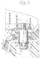
- Figure 8 shows a second embodiment where the stop means are in form of a capsule element 50 fitted on the lower end of the respective stud 21 and having a plurality of radial flaps 53 which are elastically deflectable.
- Figure 9 shows a variant wherein the stud 21 is held in place by a spring element forced within the foam of the steering-wheel, this element being in form a washer 60 with internal radial flaps 60a which are deformed on installation of the stud 21 as a result of the engagement of a conical portion 61 thereof, until they enter a groove 62.
- Figure 10 shows the washer 60 in plan view.
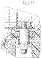
- Figure 11 shows a variant with a split spring ring 60 received within a groove 62 and held by hooks of the steering-wheel frame.
- the lower end of the stud has a head which can be engaged by a wrench, for removal.
Landscapes
- Engineering & Computer Science (AREA)
- Mechanical Engineering (AREA)
- Physics & Mathematics (AREA)
- Acoustics & Sound (AREA)
- Steering Controls (AREA)
- Air Bags (AREA)
- Emergency Alarm Devices (AREA)
Abstract
Description
- The present invention relates to horn actuating devices for motor-vehicle steering-wheels, particularly steering-wheels provided with an air-bag.
- The applicant has already proposed in Italian patent application no. TO98A000795 filed on 17/09/1998 (still secret at the priority date of the present application) a motor-vehicle steering-wheel comprising:
- a metal frame, including a hub, a rim and a plurality of spokes connecting the hub to the rim,
- an actuating element which is mounted above the frame of the steering-wheel so as to be movable between a raised rest position and a lowered position for horn actuation,
- spring means interposed between said actuating element and said steering-wheel frame for biasing the actuating element towards its raised position,
- a horn actuating device, interposed between the actuating element and the hub and comprising at least a first electric contact rigidly connected to the frame of the steering-wheel and at least a second electric contact movable with the actuating element and adapted for co-operating with said first electric contact for actuating the horn,
- wherein said spring means are constituted by a plurality of springs, each having a base portion fixedly supported on the steering-wheel frame, and a flexible portion operatively associated with the actuating element and having free end bent towards the steering-wheel frame and adapted to form said second electric contact co-operating with said first electric contact,
- wherein said springs are mounted on respective supports of plastic material which are connected to each other by a flexible strip of plastic material, in which there are embedded two conductive strips which are electrically connected to each spring and said first electric contact co-operating therewith, so as to form a pre-assembled unit accommodated on the steering-wheel frame,
- and wherein said supports of plastic material of the springs include guide bushes wherein studs are slidable which are rigidly connected to the actuating element so as to be movable therewith, stop means being interposed between the lower end of each stud and the steering-wheel frame to limit the upward travel of the actuating element with respect to the steering-wheel frame.
- The actuating element of the device can be constituted by the lower rigid wall of a housing for an air-bag associated with the steering-wheel, or it can be constituted simply by a steering-wheel hub covering element which hides the hub of the steering-wheel from view.
- The object of the present invention is that of further simplifying the structure of the previously proposed steering-wheel so that the horn actuating device can be mounted on this steering-wheel with particularly easy and rapid operations.
In view of achieving this object, the invention provides a steering-wheel having all the above indicated features wherein said stop means provided at the lower end of each stud projecting from the actuating element are elastically deformable, so as to enable rapid installation of said studs of the actuating element within said guide bushes forming part of said pre-assembled unit. - Some advantageous embodiments of the stop means provided at the lower end of each guiding stud projecting from the actuating element are defined in the annexed sub-claims.
- Further features and advantages of the invention will become apparent from the description which follows with reference to the annexed drawings, given purely by way of non-limiting example, in which:
- figure 1 is a diagrammatic view of a steering-wheel according to the previous proposal,
- figure 2 is a perspective view of the steering-wheel of figure 1, with the air-bag housing removed,
- figure 3 is a perspective view of the horn control unit which is provided within the steering-wheel,
- figure 4 is a partial cross-sectional view of the steering-wheel according to the previous proposal,
- figure 5 shows a variant of a detail of figure 4 according to the present invention,
- figure 6 is a side view of a detail of figure 5,
- figures 7, 8 show two further variants, and
- figures 9, 10 and 11 show two further variants.
- With reference to figure 1-4, numeral 1 generally designates the motor-vehicle steering-wheel forming the subject of the previous Italian patent application of the same applicant which has been identified above. The steering-wheel 1 comprises a
metal frame 2 including a plurality ofspokes 3 connecting arim 4 to a hub (not shown in the drawings) which is to be connected to the steering shaft of the motor-vehicle. Eachspoke 3 is embedded within a body 5 of plastic material and has anintermediate portion 6 providing a support for the horn actuating device associated with the steering-wheel 1. This device is generally designated by reference numeral 7 and comprises threemetal springs 8 each formed by a metal strip bent substantially in a U-shape and arranged horizontally, with its cavity facing towards the steering-wheel axis. Eachspring 8 has a base portion 9 which rests above aflattened support 10 of plastic material. More precisely, the base portion 9 of eachspring 8 rests on, and is in electric contact with,projections 11 of aconductive metal leaf 12 which is embedded within the body of plastic material ofsupport 10. Theconductive leaf 12 extends into two flattened appendages 13 (figure 3) which project outwardly from the plastic body ofsupport 10 and are in electric contact with an electricallyconductive strip 14 which is embedded within the body of aflexible strip 15 of plastic material connecting the three supports 10 to each other. Within theflexible strip 15 of plastic material there is also embedded a second electricallyconductive strip 16 electrically connected to aterminal 17 projecting outwardly fromstrip 15 at the location of eachspring 8 and having its free end fitted at 17a (figure 4) to therespective support 10. Theflexible strip 15 of plastic material is also rigidly connected to, and preferably is moulded in one piece with the body of plastic material of aconnector 18, which is for co-operation with a mating connector for connecting the twoelectric strips connector 18 is a female connector which is for co-operation with a male connector. - Each
spring 8 has aflexible portion 19 which is pressed elastically against the lower surface of awall 20 forming the bottom wall of a housing of an air-bag associated with the steering-wheel 1. This housing, as well as the air-bag, are not illustrated in the annexed drawings, since these components can be made in any known way and do not fall within the scope of the invention. The air-bag housing could also be replaced, as already indicated in the foregoing, simply by a steering-wheel hub covering element. The entire air-bag housing is resiliently supported above thespring portions 19 of the threesprings 8. This movement is guided by the slidable engagement of three shafts or studs 21 (only one of which is shown in figure 4) which are secured to thebottom wall 20 of the air-bag housing, or the hub covering element, within the respective guidingbushes 22 forming part of thesupports 10 of plastic material, which are secured to thespokes 3 of the steering-wheel 3. - In the case forming the subject of the previous proposal of the applicant, shown in figures 1-4, each
stud 21 has a threadedportion 23 which is secured to therespective bottom wall 20 by means of anut 24 and a lower head 21a adapted to act as a stop element co-operating with the lower end of therespective bush 22 in order to limit the upward travel of the air-bag housing. It is this portion of the device which is modified by the present invention, as will be described hereinafter. Eachbush 22 also incorporates a stop tooth 25 (figure 4) acting as a stop element for limiting the upward movement of thespring portion 19 of eachspring 8. - The
appendage 17 associated with eachsupport 10 constitutes a first fixed electric contact adapted to co-operate with a second movable electric contact constituted by a downwardlybent end 26 of thespring portion 19 of eachspring 8. After that a force is applied to the housing of the air-bag, or the hub covering element, thebottom wall 20 moves downwordly, causing a lowering of theflexible portion 19 of one ormore springs 8, so that the respectivemovable contact 26 is caused to rest against the respective fixedcontact 17, thus closing the electric circuit and causing actuation of the horn. - As clearly apparent from the foregoing description, the entire unit shown in figure 3, comprising the
flexible strip 15 with theconnector 18 and the three supports 10 carrying thesprings 8, can be assembled and mounted with simple and rapid operations on the frame of the steering-wheel (see figure 2). Due to the flexibility ofstrip 15, the device has a certain degree of adaptability to different types of steering-wheels. - As already indicated in the foregoing with reference to figure 4, in the case of the previously proposed steering-wheel, each
stud 21 was provided with a head 21a adapted to act as a stop means co-operating with the lower end of therespective bush 22. Therefore, in order to mount the air-bag housing, the studs had to be inserted manually from below withinbushes 22 and screwed withinnuts 24 which were preliminarly secured toelement 20. - In order to simplify installation of the air-bag unit, according to the present invention each
stud 21 has elastically deformable stop means 50 in place of the head 21a, allowing rapid installation from above of thestud 21 within therespective guide bush 22, after that thestud 21 has been preliminarly secured toelement 20 bynut 24. In the embodiment shown in figures 5, 6, the stop means 50 are a wire spring forming a pair ofradial protrusions 51 which are elastically deformable inwards. Eachprotrusion 51 is sloped in a way to assist its moving back into acavity 52 of thestud 21 when it engages with the surface of therespective bush 22, during installation. Figure 7 shows a variant with asingle protrusion 51. - Figure 8 shows a second embodiment where the stop means are in form of a
capsule element 50 fitted on the lower end of therespective stud 21 and having a plurality ofradial flaps 53 which are elastically deflectable. Figure 9 shows a variant wherein thestud 21 is held in place by a spring element forced within the foam of the steering-wheel, this element being in form awasher 60 with internalradial flaps 60a which are deformed on installation of thestud 21 as a result of the engagement of aconical portion 61 thereof, until they enter agroove 62. Figure 10 shows thewasher 60 in plan view. Figure 11 shows a variant with asplit spring ring 60 received within agroove 62 and held by hooks of the steering-wheel frame. - As in the case of figure 9, the lower end of the stud has a head which can be engaged by a wrench, for removal.
- Naturally, while the principle of the invention remains the same, the details of construction and the embodiments may widely vary with respect to what has been described and illustrated purely by way of example, without departing from the scope of the present invention.
- In particular, it is clearly apparent that in place of the above described elastic stop means it would be possible to make use of any other form of elastic stop means adapted to enable rapid installation of the air-bag unit or the steering-wheel hub cover on the steering-wheel.
Claims (6)
- Motor-vehicle steering-wheel, comprising:a metal frame (2), including a hub, a rim (4) and a plurality of spokes (3) connecting the hub to the rim (4),an actuating element (20) which is mounted above the frame (2) of the steering-wheel so as to be movable between a raised rest position and a lowered position for horn actuation,spring means (8) interposed between said actuating element (20) and said steering-wheel frame (2) for biasing the actuating element towards its raised position,a horn actuating device, interposed between the actuating element and the hub and comprising at least a first electric contact (17) rigidly connected to the frame (2) of the steering-wheel and at least a second electric contact (26) movable with the actuating element and adapted for co-operating with said first electric contact (17) for actuating the horn,wherein said spring means are constituted by a plurality of springs (8), each having a base portion (9) fixedly supported on the steering-wheel frame (2), and a flexible portion (19) operatively associated with the actuating element (20) and having free end (26) bent towards the steering-wheel frame (2) and adapted to form said second electric contact co-operating with said first electric contact (17),wherein said springs (8) are mounted on respective supports (10) of plastic material which are connected to each other by a flexible strip (15) of plastic material, in which there are embedded two conductive strips (14, 16) which are electrically connected to each spring (8) and said first electric contact (17) co-operating therewith, so as to form a pre-assembled unit accommodated on the steering-wheel frame (2),and wherein said supports (10) of plastic material of the springs (8) include guide bushes (22) wherein guide studs (21) are slidable which are rigidly connected to the actuating element so as to be movable therewith, stop means being interposed between the lower end of each stud (21) and the steering-wheel frame to limit the upward travel of the actuating element (20) with respect to the steering-wheel frame (2),characterised in that said stop means provided at the lower end of each guide stud (21) projecting from the actuating element (20) are elastically deformable, so as to enable rapid installation of said studs (21) of the actuating element (20) within said guide bushes (22) forming part of said pre-assembled unit.
- Steering-wheel according to claim 1, characterised in that said stop means are formed by a capsule element (50) mounted on the lower end of each stud (21) and provided with a plurality of radially projecting flaps (53) which are elastically deflectable.
- Steering-wheel according to any of the previous claims, characterised in that said stop means are constituted by a wire spring (50) defining one or more radial protrusions (51) which are elastically deformable inwardly.
- Steering-wheel according to claim 2, characterised in that said stop means are constituted by a stop spring element (60) forced in the foam of the steering-wheel and co-operating with the respective stud.
- Steering-wheel according to claim 4, characterised in that said spring element is constituted by a washer (60) having a plurality of inner radial flaps (60a) which are elastically deformable and adapted to co-operate with a conical portion (61) of the respective stud (21) on installation, as well as to be received within a portion (62) of reduced diameter of said stud when installation is completed.
- Steering-wheel according to claim 1, characterised in that said spring element (60) is a split ring adapted to co-operate with a conical portion (61) of the respective stud (21) on installation, and to be received on a portion of reduced diameter (62) of said stud when installation is completed.
Priority Applications (1)
| Application Number | Priority Date | Filing Date | Title |
|---|---|---|---|
| EP05028291A EP1657117A3 (en) | 1999-09-24 | 2000-09-22 | Horn actuating device for a steering wheel |
Applications Claiming Priority (2)
| Application Number | Priority Date | Filing Date | Title |
|---|---|---|---|
| IT1999TO000821A IT1308842B1 (en) | 1999-09-24 | 1999-09-24 | OPERATOR DEVICE FOR HORN WARNING FOR A DIACTION WHEEL. |
| ITTO990821 | 1999-09-24 |
Related Child Applications (1)
| Application Number | Title | Priority Date | Filing Date |
|---|---|---|---|
| EP05028291A Division EP1657117A3 (en) | 1999-09-24 | 2000-09-22 | Horn actuating device for a steering wheel |
Publications (3)
| Publication Number | Publication Date |
|---|---|
| EP1099604A2 true EP1099604A2 (en) | 2001-05-16 |
| EP1099604A3 EP1099604A3 (en) | 2004-09-01 |
| EP1099604B1 EP1099604B1 (en) | 2005-12-28 |
Family
ID=11418092
Family Applications (2)
| Application Number | Title | Priority Date | Filing Date |
|---|---|---|---|
| EP05028291A Withdrawn EP1657117A3 (en) | 1999-09-24 | 2000-09-22 | Horn actuating device for a steering wheel |
| EP00830633A Expired - Lifetime EP1099604B1 (en) | 1999-09-24 | 2000-09-22 | "Horn actuating device for a motor-vehicle steering wheel" |
Family Applications Before (1)
| Application Number | Title | Priority Date | Filing Date |
|---|---|---|---|
| EP05028291A Withdrawn EP1657117A3 (en) | 1999-09-24 | 2000-09-22 | Horn actuating device for a steering wheel |
Country Status (4)
| Country | Link |
|---|---|
| US (1) | US6457379B1 (en) |
| EP (2) | EP1657117A3 (en) |
| DE (1) | DE60025140T2 (en) |
| IT (1) | IT1308842B1 (en) |
Cited By (13)
| Publication number | Priority date | Publication date | Assignee | Title |
|---|---|---|---|---|
| EP1281584A1 (en) * | 2001-08-03 | 2003-02-05 | Breed Automotive Technology, Inc. | Horn actuating device for a motor vehicle steering wheel |
| WO2004055845A1 (en) * | 2002-12-18 | 2004-07-01 | Takata-Petri Ag | Device for actuating electric functional groups, in particular horns on the steering wheels of motor vehicles |
| GB2398277A (en) * | 2003-02-13 | 2004-08-18 | Autoliv Dev | Spring mounted air bag cover with electrical switch |
| EP1481848A3 (en) * | 2003-05-28 | 2005-04-06 | Methode Electronics Malta Ltd. | Switch for generating a warning signal in a vehicle |
| US6881911B2 (en) | 2003-06-30 | 2005-04-19 | Takata Corporation | Horn switch gear and airbag system |
| EP1640214A1 (en) * | 2004-09-24 | 2006-03-29 | Takata Corporation | Horn switch gear, airbag system comprising this Horn switch gear, and steering device comprising this horn switch gear |
| DE102009043372B4 (en) * | 2009-09-29 | 2014-03-13 | Autoliv Development Ab | Horn activation device and safety arrangement with a horn activation device |
| DE102008023004B4 (en) * | 2008-05-09 | 2014-04-03 | Autoliv Development Ab | Hupenaktivierungseinrichtung and safety device with such a Hupenaktivierungseinrichtung |
| WO2015097144A1 (en) * | 2013-12-23 | 2015-07-02 | Autoliv Development Ab | Airbag module |
| DE102016117001A1 (en) | 2016-09-09 | 2018-03-15 | Autoliv Development Ab | Horn activation device |
| WO2018141540A1 (en) * | 2017-02-06 | 2018-08-09 | Trw Automotive Safety Systems Gmbh | Horn actuation unit |
| EP3499076A1 (en) * | 2017-12-15 | 2019-06-19 | Vibracoustic Forsheda AB | A damper unit, a damper assembly, and a method for making a damper unit |
| WO2021074103A1 (en) * | 2019-10-18 | 2021-04-22 | Autoliv Development Ab | Acoustic warning device for a vehicle steering wheel |
Families Citing this family (35)
| Publication number | Priority date | Publication date | Assignee | Title |
|---|---|---|---|---|
| DE29805207U1 (en) * | 1998-03-23 | 1998-06-04 | TRW Automotive Safety Systems GmbH, 63743 Aschaffenburg | Steering wheel with an airbag |
| DE20108596U1 (en) * | 2001-05-22 | 2001-09-27 | TRW Automotive Safety Systems GmbH & Co. KG, 63743 Aschaffenburg | Airbag module and vehicle steering wheel with airbag module |
| US6830263B2 (en) * | 2002-02-08 | 2004-12-14 | Key Safety Systems, Inc. | Method for attaching an airbag module |
| DE20204461U1 (en) * | 2002-03-20 | 2002-07-25 | TRW Automotive Safety Systems GmbH & Co. KG, 63743 Aschaffenburg | Assembly with locking elements |
| US6616181B1 (en) * | 2002-04-05 | 2003-09-09 | Breed Automotive Tedhnology, Inc. | Horn mechanism featuring immunity to cushion fold |
| US7437980B2 (en) * | 2002-05-29 | 2008-10-21 | Massachusetts Institute Of Technology | Flux-biased electromagnetic fast tool servo systems and methods |
| US7574947B2 (en) * | 2002-05-29 | 2009-08-18 | Massachusetts Institute Of Technology | Rotary fast tool servo system and methods |
| US7765905B2 (en) * | 2002-05-29 | 2010-08-03 | Massachusetts Institute Of Technology | Magnetic micropositioner and method of providing the same |
| US7275468B2 (en) * | 2002-05-29 | 2007-10-02 | Massachusetts Institute Of Technology | Rotary fast tool servo system and methods |
| US6942247B2 (en) * | 2003-03-12 | 2005-09-13 | Delphi Technologies, Inc. | Driver airbag formed contact spring |
| US7059631B2 (en) * | 2003-04-29 | 2006-06-13 | Toyoda Gosei Co., Ltd. | Method and apparatus for coupling a driver's side airbag to a steering wheel |
| DE20307096U1 (en) * | 2003-05-07 | 2003-10-09 | Trw Automotive Safety Sys Gmbh | Assembly consisting of a steering wheel and an airbag module |
| US7268309B2 (en) * | 2003-06-30 | 2007-09-11 | Takata Corporation | Horn switch gear and airbag system |
| US7616084B2 (en) * | 2003-10-31 | 2009-11-10 | Massachusetts Institute Of Technology | Variable reluctance fast positioning system and methods |
| US7556281B2 (en) * | 2004-03-16 | 2009-07-07 | Toyoda Gosei Co., Ltd. | Stamped airbag retention members and method of airbag assembly |
| US7464959B2 (en) * | 2005-03-01 | 2008-12-16 | Trw Vehicle Safety Systems Inc. | Apparatus having a mechanism for limiting the movement of an air bag module relative to a steering wheel |
| US7348508B2 (en) * | 2006-05-05 | 2008-03-25 | Delphi Technologies, Inc. | Horn switch apparatus for a vehicle steering wheel |
| US8398115B2 (en) * | 2008-06-25 | 2013-03-19 | Autoliv Development Ab | Vehicle steering wheel |
| US20100219621A1 (en) * | 2009-02-27 | 2010-09-02 | Toyoda Gosei Co., Ltd. | Airbag-equipped steering wheel device |
| WO2011100960A2 (en) * | 2010-02-18 | 2011-08-25 | Trw Automotive Safety Systems Gmbh | Steering wheel having an air bag module |
| DE102011120490A1 (en) * | 2011-12-08 | 2013-06-13 | Gm Global Technology Operations, Llc | Arrangement for steering wheel of motor vehicle, has guide units formed of guide bushings and guide pins, where airbag-module is guided by guide units relative to steering wheel in axle direction of steering column receptacle of wheel |
| DE202014002484U1 (en) * | 2014-03-21 | 2015-06-29 | Dalphi Metal Espana, S.A. | Horn device for a steering wheel and steering wheel with a horn device |
| JP6596926B2 (en) * | 2015-05-26 | 2019-10-30 | Joyson Safety Systems Japan株式会社 | Contact plate, contact plate mounting method, and airbag device |
| JP6624732B2 (en) * | 2016-03-29 | 2019-12-25 | 日本プラスト株式会社 | handle |
| DE102016005020B4 (en) * | 2016-04-26 | 2019-08-14 | Dalphi Metal Espana, S.A. | Airbag unit and vehicle occupant safety system with such a gas bag unit and manufacturing method |
| JP6619293B2 (en) * | 2016-05-23 | 2019-12-11 | 株式会社ダイセル | Gas generator |
| DE102016124530A1 (en) * | 2016-12-15 | 2018-06-21 | Trw Automotive Safety Systems Gmbh | Coupling device for vibratory mounting of a gas bag module to a vehicle steering wheel |
| US11718257B2 (en) * | 2016-12-15 | 2023-08-08 | Zf Passive Safety Systems Us Inc | Coupling device for mounting an airbag module to be oscillating on a vehicle steering wheel |
| DE102018112224A1 (en) * | 2018-05-22 | 2019-11-28 | Trw Automotive Safety Systems Gmbh | Vehicle steering wheel and steering wheel assembly with such a vehicle steering wheel |
| US10926698B2 (en) * | 2018-12-17 | 2021-02-23 | Key Safety Systems, Inc. | Integrated steering wheel, vibration absorber, and driver airbag |
| DE102019105802A1 (en) * | 2019-03-07 | 2020-09-10 | Trw Automotive Safety Systems Gmbh | Horn assembly, process for their production and vehicle steering device with such a horn assembly |
| US11993204B2 (en) | 2020-12-24 | 2024-05-28 | Ronald E. Smith, JR. | Vehicle and pedestrian alert system and vehicle including an alert system |
| CN112793535A (en) * | 2021-02-26 | 2021-05-14 | 锦州锦恒汽车安全系统股份有限公司 | Vibration and noise reduction structure of steering wheel system |
| KR20240033489A (en) * | 2022-09-05 | 2024-03-12 | 현대자동차주식회사 | Steering wheel and damper unit of the steering wheel |
| FR3167595A1 (en) * | 2024-10-18 | 2026-04-24 | Autoliv Development Ab | Vehicle horn device |
Family Cites Families (12)
| Publication number | Priority date | Publication date | Assignee | Title |
|---|---|---|---|---|
| US5219415A (en) * | 1992-02-10 | 1993-06-15 | Albert Weinstein | Horn ring for a steering wheel having a restraint and method |
| US5331124A (en) * | 1992-07-20 | 1994-07-19 | Methode Electronics, Inc. | Wireless floating horn switch |
| US5303952A (en) * | 1992-12-23 | 1994-04-19 | United Technologies Automotive, Inc. | Electric signalling in a supplemental vehicle restraint system |
| US5333897A (en) * | 1993-10-25 | 1994-08-02 | General Motors Corporation | Snap lock pin inflatable restraint module mounting mechanism |
| US5627352A (en) * | 1994-09-28 | 1997-05-06 | Toyoda Gosei Co., Ltd. | Steering wheel |
| US5636858A (en) * | 1995-05-05 | 1997-06-10 | General Motors Corporation | Air bag module |
| JP3235413B2 (en) * | 1995-06-22 | 2001-12-04 | 豊田合成株式会社 | Steering wheel |
| DE19724029A1 (en) * | 1997-06-06 | 1998-12-24 | Takata Europ Gmbh | Airbag device |
| US6092832A (en) * | 1998-03-04 | 2000-07-25 | General Motors Corporation | Air bag module mounting mechanism and method of making |
| US6082758A (en) * | 1998-08-17 | 2000-07-04 | General Motors Corporation | Driver air bag horn ground spring |
| JP4538956B2 (en) * | 2000-03-17 | 2010-09-08 | タカタ株式会社 | Airbag device |
| US6276711B1 (en) * | 2000-03-27 | 2001-08-21 | Breed Automotive Technology, Inc. | Quick disconnect feature for snap-in driver air bag module |
-
1999
- 1999-09-24 IT IT1999TO000821A patent/IT1308842B1/en active
-
2000
- 2000-09-22 EP EP05028291A patent/EP1657117A3/en not_active Withdrawn
- 2000-09-22 DE DE60025140T patent/DE60025140T2/en not_active Expired - Lifetime
- 2000-09-22 EP EP00830633A patent/EP1099604B1/en not_active Expired - Lifetime
- 2000-09-25 US US09/667,302 patent/US6457379B1/en not_active Expired - Fee Related
Cited By (23)
| Publication number | Priority date | Publication date | Assignee | Title |
|---|---|---|---|---|
| EP1281584A1 (en) * | 2001-08-03 | 2003-02-05 | Breed Automotive Technology, Inc. | Horn actuating device for a motor vehicle steering wheel |
| US6722227B2 (en) | 2001-08-03 | 2004-04-20 | Key Safety Systems, Inc. | Horn actuating device for a steering wheel |
| WO2004055845A1 (en) * | 2002-12-18 | 2004-07-01 | Takata-Petri Ag | Device for actuating electric functional groups, in particular horns on the steering wheels of motor vehicles |
| US7112754B2 (en) | 2002-12-18 | 2006-09-26 | Takata-Petri Ag | Device for activating electric functional groups, in particular horns on steering wheels of motor vehicles |
| GB2398277A (en) * | 2003-02-13 | 2004-08-18 | Autoliv Dev | Spring mounted air bag cover with electrical switch |
| EP1481848A3 (en) * | 2003-05-28 | 2005-04-06 | Methode Electronics Malta Ltd. | Switch for generating a warning signal in a vehicle |
| US6881911B2 (en) | 2003-06-30 | 2005-04-19 | Takata Corporation | Horn switch gear and airbag system |
| US6995328B2 (en) | 2003-06-30 | 2006-02-07 | Takata Corporation | Horn switch gear and airbag system |
| EP1640214A1 (en) * | 2004-09-24 | 2006-03-29 | Takata Corporation | Horn switch gear, airbag system comprising this Horn switch gear, and steering device comprising this horn switch gear |
| DE102008023004B4 (en) * | 2008-05-09 | 2014-04-03 | Autoliv Development Ab | Hupenaktivierungseinrichtung and safety device with such a Hupenaktivierungseinrichtung |
| DE102009043372B4 (en) * | 2009-09-29 | 2014-03-13 | Autoliv Development Ab | Horn activation device and safety arrangement with a horn activation device |
| WO2015097144A1 (en) * | 2013-12-23 | 2015-07-02 | Autoliv Development Ab | Airbag module |
| DE102016117001A1 (en) | 2016-09-09 | 2018-03-15 | Autoliv Development Ab | Horn activation device |
| DE102016117001B4 (en) | 2016-09-09 | 2023-05-17 | Autoliv Development Ab | horn activation device |
| WO2018141540A1 (en) * | 2017-02-06 | 2018-08-09 | Trw Automotive Safety Systems Gmbh | Horn actuation unit |
| CN111699331A (en) * | 2017-12-15 | 2020-09-22 | 威巴克佛雪达公司 | Damper unit, damper assembly and method of manufacturing damper unit |
| WO2019115797A1 (en) * | 2017-12-15 | 2019-06-20 | Vibracoustic Forsheda Ab | A damper unit, a damper assembly, and a method for making a damper unit |
| CN111699331B (en) * | 2017-12-15 | 2022-03-18 | 威巴克佛雪达公司 | Damper unit, damper assembly and method of manufacturing damper unit |
| EP3499076A1 (en) * | 2017-12-15 | 2019-06-19 | Vibracoustic Forsheda AB | A damper unit, a damper assembly, and a method for making a damper unit |
| US11685435B2 (en) | 2017-12-15 | 2023-06-27 | Vibracoustic Forsheda Ab | Damper unit, a damper assembly, and a method for making a damper unit |
| WO2021074103A1 (en) * | 2019-10-18 | 2021-04-22 | Autoliv Development Ab | Acoustic warning device for a vehicle steering wheel |
| FR3102115A1 (en) * | 2019-10-18 | 2021-04-23 | Autoliv Development Ab | Vehicle steering wheel horn warning device |
| US12304387B2 (en) | 2019-10-18 | 2025-05-20 | Autoliv Development Ab | Vehicle steering wheel mounted acoustic warning device having normally closed contacts |
Also Published As
| Publication number | Publication date |
|---|---|
| DE60025140D1 (en) | 2006-02-02 |
| EP1099604B1 (en) | 2005-12-28 |
| IT1308842B1 (en) | 2002-01-11 |
| ITTO990821A1 (en) | 2001-03-24 |
| US6457379B1 (en) | 2002-10-01 |
| EP1099604A3 (en) | 2004-09-01 |
| EP1657117A3 (en) | 2006-06-07 |
| DE60025140T2 (en) | 2006-09-14 |
| EP1657117A2 (en) | 2006-05-17 |
Similar Documents
| Publication | Publication Date | Title |
|---|---|---|
| EP1099604B1 (en) | "Horn actuating device for a motor-vehicle steering wheel" | |
| US5738369A (en) | Snap-on air bag and horn switch module | |
| US9120453B2 (en) | Vibration reducing structure for steering wheel | |
| US6722227B2 (en) | Horn actuating device for a steering wheel | |
| JP4336041B2 (en) | Airbag module mounting mechanism and manufacturing method thereof | |
| US6942247B2 (en) | Driver airbag formed contact spring | |
| GB2270657A (en) | A steering wheel mounted air-bag unit | |
| MXPA05000052A (en) | A steering wheel. | |
| US7159898B2 (en) | Vehicle air bag module retention system | |
| US20020124682A1 (en) | Vehicle steering wheel | |
| US5219415A (en) | Horn ring for a steering wheel having a restraint and method | |
| US20050161308A1 (en) | Vehicle steering wheel | |
| CN213566098U (en) | Steering wheel assembly | |
| KR102340680B1 (en) | Steering wheel assembly, steering wheel and method of actuating a horn | |
| KR20090071615A (en) | Automotive safety devices including horn actuators and horn actuators | |
| EP1241055B1 (en) | Electric connector system for the steering wheel of a vehicle | |
| JP2000510412A (en) | Operation structure of alarm device in embedded integrated steering wheel | |
| WO2019154894A1 (en) | Airbag module, method for manufacturing an airbag module and steering wheel | |
| EP0827878A3 (en) | Steering wheel assembly | |
| GB2031816A (en) | Attaching hub caps to wheels | |
| KR102529927B1 (en) | Steering assembly for tractor with horn switch | |
| CN208291163U (en) | The component that air bag device and steering wheel are formed | |
| KR20250106776A (en) | Steering wheel | |
| JP3070931B2 (en) | Steering wheel with airbag device | |
| KR0140650Y1 (en) | Horn cap of car with integrated top cover assembly |
Legal Events
| Date | Code | Title | Description |
|---|---|---|---|
| PUAI | Public reference made under article 153(3) epc to a published international application that has entered the european phase |
Free format text: ORIGINAL CODE: 0009012 |
|
| AK | Designated contracting states |
Kind code of ref document: A2 Designated state(s): AT BE CH CY DE DK ES FI FR GB GR IE IT LI LU MC NL PT SE |
|
| AX | Request for extension of the european patent |
Free format text: AL;LT;LV;MK;RO;SI |
|
| PUAL | Search report despatched |
Free format text: ORIGINAL CODE: 0009013 |
|
| AK | Designated contracting states |
Kind code of ref document: A3 Designated state(s): AT BE CH CY DE DK ES FI FR GB GR IE IT LI LU MC NL PT SE |
|
| AX | Request for extension of the european patent |
Extension state: AL LT LV MK RO SI |
|
| 17P | Request for examination filed |
Effective date: 20040805 |
|
| RAP1 | Party data changed (applicant data changed or rights of an application transferred) |
Owner name: KEY SAFETY SYSTEMS, INC. |
|
| GRAP | Despatch of communication of intention to grant a patent |
Free format text: ORIGINAL CODE: EPIDOSNIGR1 |
|
| GRAS | Grant fee paid |
Free format text: ORIGINAL CODE: EPIDOSNIGR3 |
|
| AKX | Designation fees paid |
Designated state(s): DE FR GB IT |
|
| GRAA | (expected) grant |
Free format text: ORIGINAL CODE: 0009210 |
|
| AK | Designated contracting states |
Kind code of ref document: B1 Designated state(s): DE FR GB IT |
|
| REG | Reference to a national code |
Ref country code: GB Ref legal event code: FG4D |
|
| REF | Corresponds to: |
Ref document number: 60025140 Country of ref document: DE Date of ref document: 20060202 Kind code of ref document: P |
|
| ET | Fr: translation filed | ||
| PLBE | No opposition filed within time limit |
Free format text: ORIGINAL CODE: 0009261 |
|
| STAA | Information on the status of an ep patent application or granted ep patent |
Free format text: STATUS: NO OPPOSITION FILED WITHIN TIME LIMIT |
|
| 26N | No opposition filed |
Effective date: 20060929 |
|
| PGFP | Annual fee paid to national office [announced via postgrant information from national office to epo] |
Ref country code: GB Payment date: 20090807 Year of fee payment: 10 |
|
| PGFP | Annual fee paid to national office [announced via postgrant information from national office to epo] |
Ref country code: IT Payment date: 20100918 Year of fee payment: 11 |
|
| GBPC | Gb: european patent ceased through non-payment of renewal fee |
Effective date: 20100922 |
|
| REG | Reference to a national code |
Ref country code: FR Ref legal event code: ST Effective date: 20110531 |
|
| PG25 | Lapsed in a contracting state [announced via postgrant information from national office to epo] |
Ref country code: FR Free format text: LAPSE BECAUSE OF NON-PAYMENT OF DUE FEES Effective date: 20100930 |
|
| PG25 | Lapsed in a contracting state [announced via postgrant information from national office to epo] |
Ref country code: GB Free format text: LAPSE BECAUSE OF NON-PAYMENT OF DUE FEES Effective date: 20100922 |
|
| PGFP | Annual fee paid to national office [announced via postgrant information from national office to epo] |
Ref country code: FR Payment date: 20090916 Year of fee payment: 10 |
|
| PGFP | Annual fee paid to national office [announced via postgrant information from national office to epo] |
Ref country code: DE Payment date: 20110630 Year of fee payment: 12 |
|
| PG25 | Lapsed in a contracting state [announced via postgrant information from national office to epo] |
Ref country code: IT Free format text: LAPSE BECAUSE OF NON-PAYMENT OF DUE FEES Effective date: 20110922 |
|
| PG25 | Lapsed in a contracting state [announced via postgrant information from national office to epo] |
Ref country code: DE Free format text: LAPSE BECAUSE OF NON-PAYMENT OF DUE FEES Effective date: 20130403 |
|
| REG | Reference to a national code |
Ref country code: DE Ref legal event code: R119 Ref document number: 60025140 Country of ref document: DE Effective date: 20130403 |