EP1099901A2 - Adjustable rotating shaft guard - Google Patents
Adjustable rotating shaft guard Download PDFInfo
- Publication number
- EP1099901A2 EP1099901A2 EP00309313A EP00309313A EP1099901A2 EP 1099901 A2 EP1099901 A2 EP 1099901A2 EP 00309313 A EP00309313 A EP 00309313A EP 00309313 A EP00309313 A EP 00309313A EP 1099901 A2 EP1099901 A2 EP 1099901A2
- Authority
- EP
- European Patent Office
- Prior art keywords
- guard
- sleeve
- rotating shaft
- halves
- adjustable rotating
- Prior art date
- Legal status (The legal status is an assumption and is not a legal conclusion. Google has not performed a legal analysis and makes no representation as to the accuracy of the status listed.)
- Granted
Links
- 230000000717 retained effect Effects 0.000 claims abstract description 9
- 230000014759 maintenance of location Effects 0.000 claims description 16
- 230000013011 mating Effects 0.000 claims 1
- NJPPVKZQTLUDBO-UHFFFAOYSA-N novaluron Chemical compound C1=C(Cl)C(OC(F)(F)C(OC(F)(F)F)F)=CC=C1NC(=O)NC(=O)C1=C(F)C=CC=C1F NJPPVKZQTLUDBO-UHFFFAOYSA-N 0.000 description 7
- 238000012423 maintenance Methods 0.000 description 5
- 230000008878 coupling Effects 0.000 description 2
- 238000010168 coupling process Methods 0.000 description 2
- 238000005859 coupling reaction Methods 0.000 description 2
- 238000000034 method Methods 0.000 description 2
- 238000012986 modification Methods 0.000 description 2
- 230000004048 modification Effects 0.000 description 2
- 230000002093 peripheral effect Effects 0.000 description 2
- 238000005553 drilling Methods 0.000 description 1
- 238000009434 installation Methods 0.000 description 1
Images


Classifications
-
- F—MECHANICAL ENGINEERING; LIGHTING; HEATING; WEAPONS; BLASTING
- F16—ENGINEERING ELEMENTS AND UNITS; GENERAL MEASURES FOR PRODUCING AND MAINTAINING EFFECTIVE FUNCTIONING OF MACHINES OR INSTALLATIONS; THERMAL INSULATION IN GENERAL
- F16P—SAFETY DEVICES IN GENERAL; SAFETY DEVICES FOR PRESSES
- F16P1/00—Safety devices independent of the control and operation of any machine
- F16P1/02—Fixed screens or hoods
-
- Y—GENERAL TAGGING OF NEW TECHNOLOGICAL DEVELOPMENTS; GENERAL TAGGING OF CROSS-SECTIONAL TECHNOLOGIES SPANNING OVER SEVERAL SECTIONS OF THE IPC; TECHNICAL SUBJECTS COVERED BY FORMER USPC CROSS-REFERENCE ART COLLECTIONS [XRACs] AND DIGESTS
- Y10—TECHNICAL SUBJECTS COVERED BY FORMER USPC
- Y10T—TECHNICAL SUBJECTS COVERED BY FORMER US CLASSIFICATION
- Y10T74/00—Machine element or mechanism
- Y10T74/21—Elements
- Y10T74/219—Guards
- Y10T74/2191—Guards for rotary member
Definitions
- the present invention relates generally to guards for rotating machinery and more specifically to an adjustable rotating shaft guard which may be modified to accommodate different shaft heights and lengths.
- a problem frequently encountered with shielding rotating shafts is the lack of a universal guard which may be adapted to cover a variety of rotating shaft set-ups. Most guards are custom made specifically for a particular piece of machinery. Building custom guards is both time consuming and expensive, since a maintenance worker must use many hours to fabricate the guard and then install it. Further, many guards once installed are not easily removable. Guards must be periodically removed to replace a coupler, clutch, or to provide maintenance to a machine.
- the primary objective of the present invention is to provide an adjustable rotating shaft guard which may be modified to fit different machine set-ups and which provides efficient access for maintenance.
- an adjustable rotating shaft guard includes a first guard half, and a second guard half.
- the first and second guard halves are attached to some type of base, such as a pedestal, a foundation, or a machine.
- the pedestals are preferably available in various heights.
- the first and second guard halves are retained by the base such that they contact each other to fully cover a rotating shaft or coupler.
- a half sleeve preferably extends outward from at least one end of the first and second guard halves.
- the top of each guard half is fastened to each other.
- the first and second guard halves are preferably fabricated from a high impact plastic.
- the bottom area of the first and second guard halves preferably have a plurality of cutting lines which provide a reference for sawing to a specific height.
- the half sleeves also have a plurality of cutting lines which provide a reference for sawing to a specific length.
- an adjustable rotating shaft guard in a second embodiment, includes a first sleeve guard half, a second sleeve guard half and two sets of two end cap halves.
- a flange extends outward from each side of the first and second sleeve guard halves. The flanges of the first and second sleeve halves are fastened to each other.
- Each pair of end cap halves are attached to each end of the first and second sleeve guard halves.
- One or both ends of the first and second sleeve halves may be supported by an adjustable leg set.
- One or both ends of the first and second sleeve guard halves may be supported by a mounting plate.
- the first sleeve guard half, the second sleeve guard half, and the pair of end cap halves are preferably fabricated from a high impact plastic.
- the ends of the first and second sleeve guard halves preferably have a plurality of cutting lines which provide a reference for sawing to a specific length.
- an object of the present invention to provide an adjustable rotating shaft guard which may be adjusted to different lengths and heights to accommodate different machine set-ups.
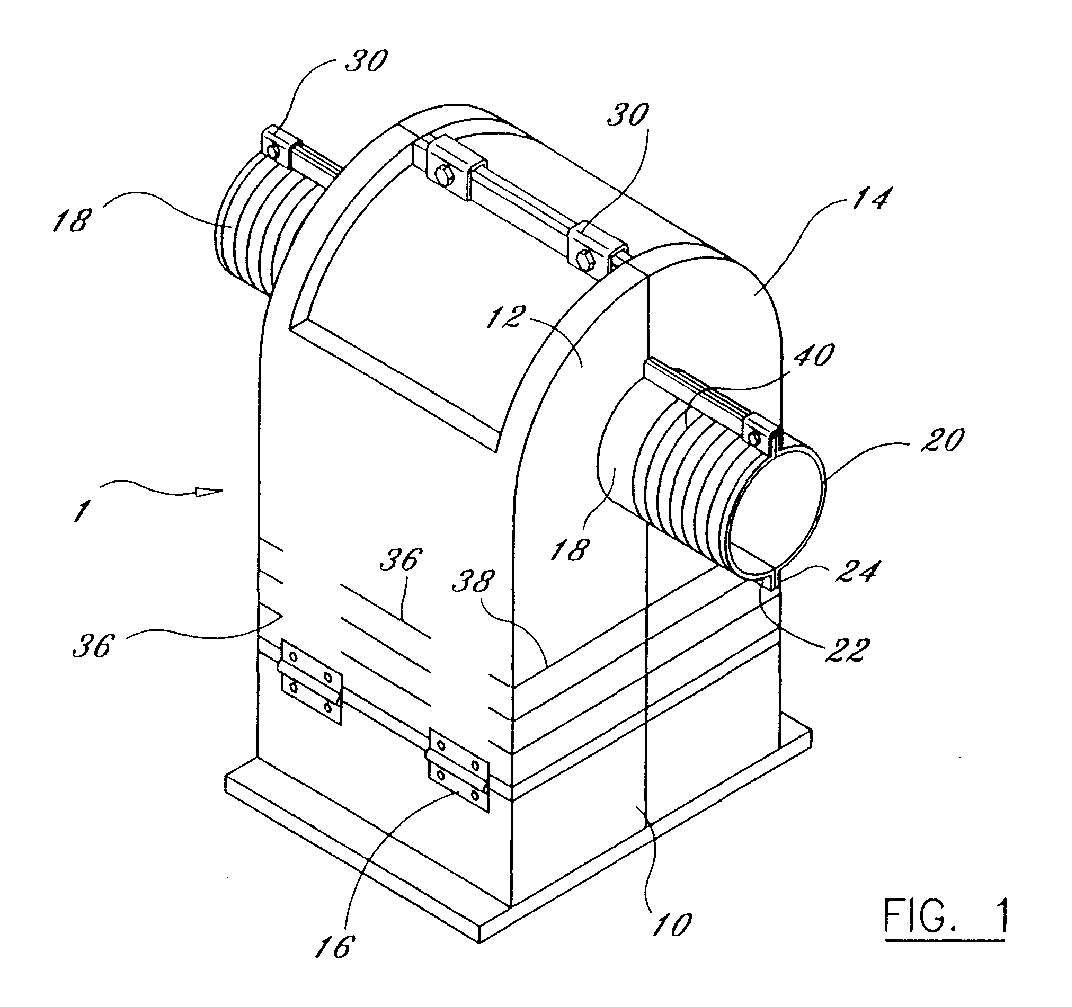
- Figure 1 is a perspective view of an adjustable rotating shaft guard in accordance with the present invention.
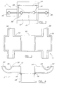
- FIG. 2 is a top view of an adjustable rotating shaft guard in accordance with the present invention.
- Figure 3 is a top view of an adjustable rotating shaft guard with the guard halves folded out in accordance with the present invention.
- Figure 4 is a front view of an adjustable rotating shaft guard with the guard halves folded out in accordance with the present invention.
- Figure 4a is a front view of an adjustable rotating shaft guard with the guard halves folded out and pivotally attached to a foundation in accordance with the present invention.
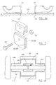
- Figure 5 is an enlarged perspective view of a retention clip, bolt, and nut before assembly of the two guard halves in accordance with the present invention.
- Figure 6 is a top cut-away view of an adjustable rotating shaft guard with a pair of rotating shafts covered thereby in accordance with the present invention.
- Figure 7 is a exploded perspective view of a second embodiment of an adjustable rotating shaft guard in accordance with the present invention.
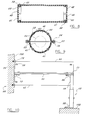
- Figure 8 is a side cross-sectional view of a first sleeve guard half in accordance with the present invention.
- Figure 9 is an cross-sectional view of a second embodiment of an adjustable rotating shaft guard in accordance with the present invention.
- Figure 10 is a side view of a second embodiment of an adjustable rotating shaft guard with a mounting plate and set of adjustable legs attached thereto in accordance with the present invention.
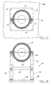
- Figure 11 is a cross-sectional view of a second embodiment of an adjustable rotating shaft guard with a mounting plate attached thereto in accordance with the present invention.
- Figure 12 is a cross-sectional view of a second embodiment of an adjustable rotating shaft guard with a set of adjustable legs attached thereto in accordance with the present invention.
- the adjustable rotating shaft guard 1 includes a first guard half 12 and a second guard half 14.
- the first and second guard halves may be attached to a pedestal 10, a foundation 101, or a machine.
- the pedestal 10 is preferably available in various heights.
- the first and second guard halves are retained by the base such that they contact each other to fully cover a rotating shaft or coupler.
- a bottom of the first guard half 12 is preferably pivotally mounted to the pedestal 10, foundation 101, or machine with at least one hinge 16.
- a bottom of the second guard half 14 is also preferably pivotally mounted to the pedestal 10, foundation 101, or machine with at least one hinge 16.
- the hinge 16 may be a stationary or removable type.
- the first and second guard halves may also be retained by the pedestal 10, foundation 101, or machine with other methods besides hinges, such as latches, fasteners, and any other suitable attachment method.
- a first half sleeve 18 preferably extends outward from at least one end of the first guard half 12.
- a second half sleeve 20 preferably extends outward from at least one end of the second guard half 14.
- a first flange 22 preferably extends outward from at least one side of the first sleeve 18.
- a second flange 24 preferably extends outward from at least one side of the second sleeve 20.
- a first top flange 26 is preferably formed on a top of the first guard half 12 and a second top flange 28 is preferably formed on a top of the second guard half 14.
- the first and second guard halves are preferably fabricated from a high impact plastic. It is also preferable that the high impact plastic have a clear or translucent color to allow the shaft or coupling to be viewed without removing the guard halves.
- FIG. 5 shows a perspective view of a retention clip 30, bolt 32, and lock nut 34 which retain the first guard half 12 against the second guard half 14.
- the retention clip 30 is preferably used as a template for drilling a hole in the flanges 22, 24, 26, and 28.
- the retention clip 30 is placed over the flanges and the retention clip is retained in place with a bolt 32 and lock nut 34, or any suitable locking fastener. If a lock nut 34 or nonlocking fastener is not used, the nut may vibrate off the bolt allowing the retention clip 30 to also vibrate off the flanges.
- the retention clip 30 may be replaced with a latch, a lock, or any other suitable retention device which firmly retains the first guard half 12 against the second guard half 14.
- Front cutting lines 36 are preferably formed on a bottom front of the first and second guard halves.
- End cutting lines 38 are preferably formed on at least one bottom end of the first and second guard halves.
- Sleeve exterior ribs 40 are preferably formed on the first and second flanges.
- the cutting lines are preferably shallow depressions formed in the surface which act as a guide for cutting the first and second guard halves to reduce the height thereof for custom installation. The length of each sleeve may be reduced by cutting along the sleeve cutting lines 40.
- Figure 6 shows a top cut-away view of the adjustable rotating shaft guard 1 covering a first rotating shaft 100 which is coupled to a second rotating shaft 104 through a rotary coupler 102.
- the adjustable rotating shaft guard 1 may be installed in the following manner.
- the length of the rotating shafts to be covered are measured.
- the half sleeves are cut to the lengths needed to cover the rotating shafts.
- the height of the rotating shafts from a mounting surface is also measured.
- the bottoms of the first and second guard halves are cut to the heights required to center the rotating shafts within the first and second half sleeves.
- Figure 7 shows a second embodiment of an adjustable rotating shaft guard 2 includes a first sleeve guard half 42, a second sleeve guard half 44 a first end cap half 46, and a second end cap half 48.
- a first flange 50 extends outward from each side of the first sleeve guard half 42.
- a second flange 51 extends outward from each side of the second sleeve guard half 44.
- the first and second flanges of the first and second sleeve guard halves are fastened against each other.
- the first and second flanges are preferably retained against each other with a plurality of retention clips 52, bolts 54, and lock nuts 56.
- the retention clip 52 may be replaced with a latch, a lock, or any other suitable retention device which firmly retains the first sleeve guard half 42 against the second sleeve guard half 44.
- a first end cap half 46 has a first peripheral flange 47 and a second end cap half 48 has a second peripheral flange 49.
- the first and second end cap halves are preferably retained in the first and second sleeve guard halves, respectively with a plurality of bolts 58 and lock nuts 60.
- a first semi-circle opening 62 is formed in the first end cap half and a second semi-circle opening 64 is formed in the second end cap half to provide clearance for a rotating shaft.
- the first sleeve guard half 42, the second sleeve guard half 44, and the pair of end cap halves are preferably fabricated from a clear or translucent color high impact plastic to allow the shaft or coupling to be viewed without removing the guard halves.
- the ends of the first and second sleeve guard halves preferably have a plurality of cutting lines 45 which provide a reference for sawing to a specific length.
- first and second sleeve guard halves may be supported by a mounting plate 66.
- One or both ends of the first and second sleeve guard halves may also be supported by an adjustable leg set 68.
- the mounting plate 66 includes a fastening plate 70 and a pair of attachment brackets 72.
- a plurality of mounting holes 74 are formed in the fastening plate 70.
- a plurality of bolts 76 are preferably used to attach the adjustable rotating shaft guard 2 to a machine 106. At least one hole is formed in a top of each attachment bracket 72 such that the flange 50 may be bolted thereto.
- the adjustable leg set 68 includes a female leg set 78 and a pair of male telescoping legs 80.
- the female leg set 78 includes a pair of female legs 82 which are attached to a cross member 84.
- a top mounting bracket 86 is attached to a top of each male telescoping leg 80.
- a hole is formed through the top mounting bracket 86 to allow thereof to be bolted to each flange 50.
- a bottom mounting bracket 88 is attached to a bottom of each female leg 82.
- a hole is formed through the bottom mounting bracket 88 to allow thereof to be bolted to a foundation 108.
- the female and male legs are preferably slotted to allow thereof to be adjusted relative to each other.
- a bolt or other fastener is used to tighten the female legs against the male legs to prevent unwanted vertical movement.
Landscapes
- Engineering & Computer Science (AREA)
- General Engineering & Computer Science (AREA)
- Mechanical Engineering (AREA)
- Sawing (AREA)
- Professional, Industrial, Or Sporting Protective Garments (AREA)
- Pressure Welding/Diffusion-Bonding (AREA)
- Investigating Or Analyzing Materials By The Use Of Magnetic Means (AREA)
- Suspension Of Electric Lines Or Cables (AREA)
- Soil Working Implements (AREA)
Abstract
Description
- The present invention relates generally to guards for rotating machinery and more specifically to an adjustable rotating shaft guard which may be modified to accommodate different shaft heights and lengths.
- A problem frequently encountered with shielding rotating shafts is the lack of a universal guard which may be adapted to cover a variety of rotating shaft set-ups. Most guards are custom made specifically for a particular piece of machinery. Building custom guards is both time consuming and expensive, since a maintenance worker must use many hours to fabricate the guard and then install it. Further, many guards once installed are not easily removable. Guards must be periodically removed to replace a coupler, clutch, or to provide maintenance to a machine.
- Accordingly, there is a clearly felt need in the art for an adjustable rotating shaft guard which may be modified to fit different machine set-ups and which provides efficient access for maintenance.
- The primary objective of the present invention is to provide an adjustable rotating shaft guard which may be modified to fit different machine set-ups and which provides efficient access for maintenance.
- According to the present invention, an adjustable rotating shaft guard includes a first guard half, and a second guard half. The first and second guard halves are attached to some type of base, such as a pedestal, a foundation, or a machine. The pedestals are preferably available in various heights. The first and second guard halves are retained by the base such that they contact each other to fully cover a rotating shaft or coupler. A half sleeve preferably extends outward from at least one end of the first and second guard halves. Preferably, the top of each guard half is fastened to each other. The first and second guard halves are preferably fabricated from a high impact plastic. The bottom area of the first and second guard halves preferably have a plurality of cutting lines which provide a reference for sawing to a specific height. The half sleeves also have a plurality of cutting lines which provide a reference for sawing to a specific length.
- In a second embodiment, an adjustable rotating shaft guard includes a first sleeve guard half, a second sleeve guard half and two sets of two end cap halves. A flange extends outward from each side of the first and second sleeve guard halves. The flanges of the first and second sleeve halves are fastened to each other. Each pair of end cap halves are attached to each end of the first and second sleeve guard halves. One or both ends of the first and second sleeve halves may be supported by an adjustable leg set. One or both ends of the first and second sleeve guard halves may be supported by a mounting plate. The first sleeve guard half, the second sleeve guard half, and the pair of end cap halves are preferably fabricated from a high impact plastic. The ends of the first and second sleeve guard halves preferably have a plurality of cutting lines which provide a reference for sawing to a specific length.
- Accordingly, it is an object of the present invention to provide an adjustable rotating shaft guard which may be adjusted to different lengths and heights to accommodate different machine set-ups.
- It is a further object of the present invention to provide an adjustable rotating shaft guard which is fabricated of a high impact plastic.
- It is yet a further object of the present invention to provide an adjustable rotating shaft guard which may be fastened to existing machinery without requiring a pedestal.
- Finally, it is another object of the present invention to provide an adjustable rotating shaft guard which may be efficiently removed for maintenance purposes.
- These and additional objects, advantages, features and benefits of the present invention will become apparent from the following specification.
- Figure 1 is a perspective view of an adjustable rotating shaft guard in accordance with the present invention.
- Figure 2 is a top view of an adjustable rotating shaft guard in accordance with the present invention.
- Figure 3 is a top view of an adjustable rotating shaft guard with the guard halves folded out in accordance with the present invention.
- Figure 4 is a front view of an adjustable rotating shaft guard with the guard halves folded out in accordance with the present invention.
- Figure 4a is a front view of an adjustable rotating shaft guard with the guard halves folded out and pivotally attached to a foundation in accordance with the present invention.
- Figure 5 is an enlarged perspective view of a retention clip, bolt, and nut before assembly of the two guard halves in accordance with the present invention.
- Figure 6 is a top cut-away view of an adjustable rotating shaft guard with a pair of rotating shafts covered thereby in accordance with the present invention.
- Figure 7 is a exploded perspective view of a second embodiment of an adjustable rotating shaft guard in accordance with the present invention.
- Figure 8 is a side cross-sectional view of a first sleeve guard half in accordance with the present invention.
- Figure 9 is an cross-sectional view of a second embodiment of an adjustable rotating shaft guard in accordance with the present invention.
- Figure 10 is a side view of a second embodiment of an adjustable rotating shaft guard with a mounting plate and set of adjustable legs attached thereto in accordance with the present invention.
- Figure 11 is a cross-sectional view of a second embodiment of an adjustable rotating shaft guard with a mounting plate attached thereto in accordance with the present invention.
- Figure 12 is a cross-sectional view of a second embodiment of an adjustable rotating shaft guard with a set of adjustable legs attached thereto in accordance with the present invention.
- With reference now to the drawings, and particularly to figure 1, there is shown a perspective view of an adjustable rotating shaft guard 1. With reference to figures 2 - 4a, the adjustable rotating shaft guard 1 includes a
first guard half 12 and asecond guard half 14. The first and second guard halves may be attached to apedestal 10, afoundation 101, or a machine. Thepedestal 10 is preferably available in various heights. The first and second guard halves are retained by the base such that they contact each other to fully cover a rotating shaft or coupler. A bottom of thefirst guard half 12 is preferably pivotally mounted to thepedestal 10,foundation 101, or machine with at least onehinge 16. A bottom of thesecond guard half 14 is also preferably pivotally mounted to thepedestal 10,foundation 101, or machine with at least onehinge 16. Thehinge 16 may be a stationary or removable type. - The first and second guard halves may also be retained by the
pedestal 10,foundation 101, or machine with other methods besides hinges, such as latches, fasteners, and any other suitable attachment method. Afirst half sleeve 18 preferably extends outward from at least one end of thefirst guard half 12. Asecond half sleeve 20 preferably extends outward from at least one end of thesecond guard half 14. Afirst flange 22 preferably extends outward from at least one side of thefirst sleeve 18. Asecond flange 24 preferably extends outward from at least one side of thesecond sleeve 20. A firsttop flange 26 is preferably formed on a top of thefirst guard half 12 and asecond top flange 28 is preferably formed on a top of thesecond guard half 14. The first and second guard halves are preferably fabricated from a high impact plastic. It is also preferable that the high impact plastic have a clear or translucent color to allow the shaft or coupling to be viewed without removing the guard halves. - Figure 5 shows a perspective view of a
retention clip 30,bolt 32, and locknut 34 which retain thefirst guard half 12 against thesecond guard half 14. Theretention clip 30 is preferably used as a template for drilling a hole in theflanges retention clip 30 is placed over the flanges and the retention clip is retained in place with abolt 32 andlock nut 34, or any suitable locking fastener. If alock nut 34 or nonlocking fastener is not used, the nut may vibrate off the bolt allowing theretention clip 30 to also vibrate off the flanges. Theretention clip 30 may be replaced with a latch, a lock, or any other suitable retention device which firmly retains thefirst guard half 12 against thesecond guard half 14. -
Front cutting lines 36 are preferably formed on a bottom front of the first and second guard halves.End cutting lines 38 are preferably formed on at least one bottom end of the first and second guard halves.Sleeve exterior ribs 40 are preferably formed on the first and second flanges. The cutting lines are preferably shallow depressions formed in the surface which act as a guide for cutting the first and second guard halves to reduce the height thereof for custom installation. The length of each sleeve may be reduced by cutting along the sleeve cutting lines 40. Figure 6 shows a top cut-away view of the adjustable rotating shaft guard 1 covering a firstrotating shaft 100 which is coupled to a secondrotating shaft 104 through arotary coupler 102. - The adjustable rotating shaft guard 1 may be installed in the following manner. The length of the rotating shafts to be covered are measured. The half sleeves are cut to the lengths needed to cover the rotating shafts. The height of the rotating shafts from a mounting surface is also measured. The bottoms of the first and second guard halves are cut to the heights required to center the rotating shafts within the first and second half sleeves.
- Figure 7 shows a second embodiment of an adjustable
rotating shaft guard 2 includes a firstsleeve guard half 42, a second sleeve guard half 44 a firstend cap half 46, and a secondend cap half 48. Afirst flange 50 extends outward from each side of the firstsleeve guard half 42. Asecond flange 51 extends outward from each side of the secondsleeve guard half 44. The first and second flanges of the first and second sleeve guard halves are fastened against each other. The first and second flanges are preferably retained against each other with a plurality of retention clips 52,bolts 54, and lock nuts 56. Theretention clip 52 may be replaced with a latch, a lock, or any other suitable retention device which firmly retains the firstsleeve guard half 42 against the secondsleeve guard half 44. A firstend cap half 46 has a firstperipheral flange 47 and a secondend cap half 48 has a secondperipheral flange 49. With reference to figures 8 and 9, the first and second end cap halves are preferably retained in the first and second sleeve guard halves, respectively with a plurality ofbolts 58 and lock nuts 60. A first semi-circle opening 62 is formed in the first end cap half and a second semi-circle opening 64 is formed in the second end cap half to provide clearance for a rotating shaft. - The first
sleeve guard half 42, the secondsleeve guard half 44, and the pair of end cap halves are preferably fabricated from a clear or translucent color high impact plastic to allow the shaft or coupling to be viewed without removing the guard halves. The ends of the first and second sleeve guard halves preferably have a plurality of cuttinglines 45 which provide a reference for sawing to a specific length. - With reference to figure 10 - 12, one or both ends of the first and second sleeve guard halves may be supported by a mounting
plate 66. One or both ends of the first and second sleeve guard halves may also be supported by an adjustable leg set 68. The mountingplate 66 includes afastening plate 70 and a pair ofattachment brackets 72. A plurality of mountingholes 74 are formed in thefastening plate 70. A plurality ofbolts 76 are preferably used to attach the adjustablerotating shaft guard 2 to amachine 106. At least one hole is formed in a top of eachattachment bracket 72 such that theflange 50 may be bolted thereto. - The adjustable leg set 68 includes a female leg set 78 and a pair of
male telescoping legs 80. The female leg set 78 includes a pair offemale legs 82 which are attached to across member 84. A top mountingbracket 86 is attached to a top of eachmale telescoping leg 80. A hole is formed through the top mountingbracket 86 to allow thereof to be bolted to eachflange 50. Abottom mounting bracket 88 is attached to a bottom of eachfemale leg 82. A hole is formed through thebottom mounting bracket 88 to allow thereof to be bolted to afoundation 108. The female and male legs are preferably slotted to allow thereof to be adjusted relative to each other. A bolt or other fastener is used to tighten the female legs against the male legs to prevent unwanted vertical movement. - While particular embodiments of the invention have been shown and described, it will be obvious to those skilled in the art that changes and modifications may be made without departing from the invention in its broader aspects, and therefore, the aim in the appended claims is to cover all such changes and modifications as fall within the true spirit and scope of the invention.
Claims (10)
- An adjustable rotating shaft guard comprising:a base;a first guard half having an opening in each end thereof, said first guard half being retained by said base; anda second guard half having an opening in each end thereof, said second guard half being retained by said base, said first guard half mating to said second guard half such that said first and second guard halves cover at least one rotating shaft.
- The adjustable rotating shaft guard of claim 1, further comprising:
a first half sleeve extending from at least one end of said first guard half and a second half sleeve extending from at least one end of said second guard half. - The adjustable rotating shaft guard of claim 2, wherein:
a first flange extending outward from at least one side of said first sleeve half and a second flange extending outward from at least one side of said second sleeve half. - The adjustable rotating shaft guard of claim 1, wherein:
a bottom of said first guard half being pivotally attached to a top of said base and a bottom of said second guard half being pivotally attached to a top said base. - The adjustable rotating shaft guard of claim 1, wherein:
a first top flange extending from a top of said first guard half and a second top flange extending from a top of said second guard half. - The adjustable rotating shaft guard of claim 5, further comprising:
at least one retention device being used to retain said first guard half against said second guard half. - The adjustable rotating shaft guard of claim 5, further comprising:
said at least one retention device being at least one retention clip, said at least one retention clip being placed over said first and second top flanges to retain said first and second guard halves against each other. - An adjustable rotating shaft guard comprising:a first sleeve guard half having an opening in each end thereof;a second sleeve guard half having an opening in each end thereof, said first and second sleeve guard halves being attached to each other; andan end cap being attached to each end of said first and second sleeve guard halves, each said end cap having a hole formed therethrough.
- The adjustable rotating shaft guard of claim 8, further comprising:
a first flange extending outward from each side of said first sleeve guard half, a second flange extending outward from each side of said second sleeve guard half, said first and second flanges being attached to each. - The adjustable rotating shaft guard of claim 9, further comprising:
at least one retention device being used to retain said first sleeve guard half against said second sleeve guard half.
Applications Claiming Priority (2)
| Application Number | Priority Date | Filing Date | Title |
|---|---|---|---|
| US09/439,513 US6241618B1 (en) | 1999-11-12 | 1999-11-12 | Adjustable rotating shaft guard |
| US439513 | 1999-11-12 |
Publications (3)
| Publication Number | Publication Date |
|---|---|
| EP1099901A2 true EP1099901A2 (en) | 2001-05-16 |
| EP1099901A3 EP1099901A3 (en) | 2002-10-16 |
| EP1099901B1 EP1099901B1 (en) | 2007-01-24 |
Family
ID=23745013
Family Applications (1)
| Application Number | Title | Priority Date | Filing Date |
|---|---|---|---|
| EP00309313A Expired - Lifetime EP1099901B1 (en) | 1999-11-12 | 2000-10-23 | Adjustable rotating shaft guard |
Country Status (4)
| Country | Link |
|---|---|
| US (1) | US6241618B1 (en) |
| EP (1) | EP1099901B1 (en) |
| AT (1) | ATE352746T1 (en) |
| DE (1) | DE60033110T2 (en) |
Cited By (4)
| Publication number | Priority date | Publication date | Assignee | Title |
|---|---|---|---|---|
| ES2184617A1 (en) * | 2001-06-12 | 2003-04-01 | Bonilla Juan Belmonte | Protector for centrifugal pump mobile elements |
| WO2003098096A1 (en) * | 2002-05-15 | 2003-11-27 | The Falk Corporation | Adjustable guard for protecting coupling connection between rotating shafts |
| EP2230438A2 (en) | 2009-03-16 | 2010-09-22 | AVL List GmbH | Adjustable contact protection |
| EP3228917A1 (en) * | 2016-04-05 | 2017-10-11 | Siemens Aktiengesellschaft | Coupling guard |
Families Citing this family (12)
| Publication number | Priority date | Publication date | Assignee | Title |
|---|---|---|---|---|
| US6726368B2 (en) | 2002-01-22 | 2004-04-27 | H & S Manufacturing Co., Inc. | Anti-wrap guard |
| US20060144201A1 (en) * | 2005-01-06 | 2006-07-06 | The Falk Corporation | Adjustable rotating shaft guard |
| US7520816B1 (en) * | 2005-09-21 | 2009-04-21 | Tencarva Machinery Company | Guard assembly for extending around a rotating shaft |
| FI20060530A0 (en) * | 2006-05-31 | 2006-05-31 | Tonttulan Takomo Oy | SKIRT |
| AU2008207607B2 (en) * | 2007-12-21 | 2015-05-14 | Weir Minerals Australia Ltd | A guard |
| US8025577B2 (en) | 2008-04-16 | 2011-09-27 | Labarge Iii William E | Coupling guard |
| US20110197706A1 (en) * | 2010-02-18 | 2011-08-18 | Alan Dean Matthes | Device to guard an end of a rotating shaft or bearing |
| US9470364B2 (en) * | 2013-04-17 | 2016-10-18 | William Cocks | Guard system for pump assembly |
| JP2016205445A (en) * | 2015-04-16 | 2016-12-08 | 株式会社荏原製作所 | Coupling guard |
| EP3118476B1 (en) * | 2015-07-15 | 2018-10-10 | Cummins Generator Technologies Limited | Adaptor for power generating system |
| EP3999753B1 (en) | 2019-07-19 | 2023-09-06 | Sew-Eurodrive GmbH & Co. KG | Gear motor, comprising a gear mechanism driven via a clutch by an electric motor |
| US12680648B2 (en) | 2022-04-26 | 2026-07-14 | Dodge Industrial Inc. | Shaft guard for a machine |
Family Cites Families (21)
| Publication number | Priority date | Publication date | Assignee | Title |
|---|---|---|---|---|
| US600375A (en) * | 1898-03-08 | Shaft-protector | ||
| US773945A (en) * | 1904-07-15 | 1904-11-01 | Max Kronauer | Lock-bar pipe. |
| US1232953A (en) | 1916-12-13 | 1917-07-10 | Thomas Mills | Guard for the scrolls of spinning-mules. |
| US1531285A (en) | 1921-08-04 | 1925-03-31 | Westinghouse Electric & Mfg Co | Coupling and bearing arrangement |
| US1665241A (en) * | 1927-02-18 | 1928-04-10 | Carl W Weiss | Universal joint |
| US1814134A (en) * | 1928-12-28 | 1931-07-14 | Eige Abraham | Insulation casing for pipe fittings, valves and the like |
| GB573972A (en) * | 1944-05-04 | 1945-12-14 | William Henry Bishop | A new or improved guard for drilling and like machines |
| US2512528A (en) * | 1945-12-08 | 1950-06-20 | Harry V Holman | Protective device for clamp screws or the like |
| US2858115A (en) * | 1956-02-23 | 1958-10-28 | Esther B Stebbins | Finned tubing |
| USD244020S (en) * | 1975-06-16 | 1977-04-12 | Hanson Richard H | Coupling guard |
| DE7615750U1 (en) * | 1976-05-18 | 1976-11-11 | Allweiler Ag, 7760 Radolfzell | CLUTCH PROTECTION DEVICE |
| US4211519A (en) * | 1977-08-29 | 1980-07-08 | Cole-Parmer Instrument Company | Fluid pump and quick release mounting arrangement therefor |
| US4324533A (en) * | 1980-02-15 | 1982-04-13 | Allis-Chalmers Corporation | Universal guard |
| US4840194A (en) * | 1988-01-14 | 1989-06-20 | Cooper Industries, Inc. | Explosion proof electrical conduit sealing fitting |
| US5054513A (en) * | 1990-08-20 | 1991-10-08 | Trueb Steven R | Protective system for P-trap |
| DE4330423C1 (en) * | 1993-09-08 | 1994-10-13 | Netzsch Mohnopumpen Gmbh | Protective housing for rotating shaft arrangements |
| US5711170A (en) | 1994-08-19 | 1998-01-27 | Maytag Corporation | Integrated tub and cabinet structure |
| US5674052A (en) * | 1995-11-14 | 1997-10-07 | Coulter International Corp. | Pinch pump having selectable pressure plate sizes and a flexible tube with attachment ribs |
| US5643181A (en) * | 1996-01-29 | 1997-07-01 | Lin; Kenny | Multipurpose massaging apparatus |
| FR2757247A1 (en) * | 1996-12-17 | 1998-06-19 | Salata Philippe | Housing for protecting personnel from either rotary or reciprocating transmission shafts |
| US6190261B1 (en) * | 1998-09-15 | 2001-02-20 | Flowserve Management Company | Pump assembly shaft guard |
-
1999
- 1999-11-12 US US09/439,513 patent/US6241618B1/en not_active Expired - Lifetime
-
2000
- 2000-10-23 AT AT00309313T patent/ATE352746T1/en not_active IP Right Cessation
- 2000-10-23 EP EP00309313A patent/EP1099901B1/en not_active Expired - Lifetime
- 2000-10-23 DE DE60033110T patent/DE60033110T2/en not_active Expired - Lifetime
Non-Patent Citations (1)
| Title |
|---|
| None |
Cited By (6)
| Publication number | Priority date | Publication date | Assignee | Title |
|---|---|---|---|---|
| ES2184617A1 (en) * | 2001-06-12 | 2003-04-01 | Bonilla Juan Belmonte | Protector for centrifugal pump mobile elements |
| WO2003098096A1 (en) * | 2002-05-15 | 2003-11-27 | The Falk Corporation | Adjustable guard for protecting coupling connection between rotating shafts |
| US7275995B2 (en) | 2002-05-15 | 2007-10-02 | Rexnord Industries, Llc | Adjustable guard for protecting coupling connection between rotating shafts |
| EP2230438A2 (en) | 2009-03-16 | 2010-09-22 | AVL List GmbH | Adjustable contact protection |
| EP3228917A1 (en) * | 2016-04-05 | 2017-10-11 | Siemens Aktiengesellschaft | Coupling guard |
| WO2017174277A1 (en) * | 2016-04-05 | 2017-10-12 | Siemens Aktiengesellschaft | Coupling guard |
Also Published As
| Publication number | Publication date |
|---|---|
| DE60033110D1 (en) | 2007-03-15 |
| EP1099901A3 (en) | 2002-10-16 |
| EP1099901B1 (en) | 2007-01-24 |
| US6241618B1 (en) | 2001-06-05 |
| DE60033110T2 (en) | 2007-11-08 |
| ATE352746T1 (en) | 2007-02-15 |
Similar Documents
| Publication | Publication Date | Title |
|---|---|---|
| US6241618B1 (en) | Adjustable rotating shaft guard | |
| US5056955A (en) | Locking device for coverings for manholes and other ground openings | |
| US4943100A (en) | Drain suited for installation in wooden floors | |
| US6207894B1 (en) | Load supporting electrical box system suited for installation in concrete and having enlarged cavity therein | |
| US20070187556A1 (en) | Vertically adjustable pipe support apparatus | |
| DE60001560T2 (en) | SPEAKER MOUNTING ARRANGEMENT FOR VEHICLE FAIRING PART | |
| US4986200A (en) | Depth gauge wheel | |
| US6237884B1 (en) | Ceiling fan mounting assembly | |
| EP1354104B1 (en) | Rail and supports therefor | |
| US6648278B1 (en) | Offset hanger | |
| US5823577A (en) | Plastic meter box bottom | |
| US5904261A (en) | Enclosures and mounting box for a trailer hitch electrical connector | |
| KR102207373B1 (en) | Frame assembly structure for installing window type air-conditioner on window sill | |
| US20040093813A1 (en) | Roof pipe chase housing system | |
| KR940002428A (en) | Construction method of soundproof wall | |
| US4073591A (en) | Composite U Joint guard-step | |
| US4930659A (en) | Drain baffle grommet for vehicle compartments | |
| KR200306637Y1 (en) | A lock device of manhole | |
| KR200203559Y1 (en) | A fixing band for drain pipe | |
| KR0134408Y1 (en) | Under and wheel guards of vehicles with tool covers | |
| JPS6131525Y2 (en) | ||
| KR200499617Y1 (en) | Fall prevention apparatus structure for manhole | |
| KR100339031B1 (en) | Ring to a higher for manhole cover fixing | |
| DE2166319B2 (en) | Universal junction box for underfloor services - has telescopic box with sealed lid and provision for coupling units | |
| KR200202611Y1 (en) | Locking device of a hinge shaft for a door closer |
Legal Events
| Date | Code | Title | Description |
|---|---|---|---|
| PUAI | Public reference made under article 153(3) epc to a published international application that has entered the european phase |
Free format text: ORIGINAL CODE: 0009012 |
|
| AK | Designated contracting states |
Kind code of ref document: A2 Designated state(s): AT BE CH CY DE DK ES FI FR GB GR IE IT LI LU MC NL PT SE |
|
| AX | Request for extension of the european patent |
Free format text: AL;LT;LV;MK;RO;SI |
|
| PUAL | Search report despatched |
Free format text: ORIGINAL CODE: 0009013 |
|
| AK | Designated contracting states |
Kind code of ref document: A3 Designated state(s): AT BE CH CY DE DK ES FI FR GB GR IE IT LI LU MC NL PT SE |
|
| AX | Request for extension of the european patent |
Free format text: AL;LT;LV;MK;RO;SI |
|
| RAP1 | Party data changed (applicant data changed or rights of an application transferred) |
Owner name: THE FALK CORPORATION |
|
| RIN1 | Information on inventor provided before grant (corrected) |
Inventor name: THE FALK CORPORATION |
|
| 17P | Request for examination filed |
Effective date: 20030411 |
|
| RIN1 | Information on inventor provided before grant (corrected) |
Inventor name: DOLL, RONALD J. |
|
| AKX | Designation fees paid |
Designated state(s): AT BE CH CY DE DK ES FI FR GB GR IE IT LI LU MC NL PT SE |
|
| 17Q | First examination report despatched |
Effective date: 20050419 |
|
| GRAP | Despatch of communication of intention to grant a patent |
Free format text: ORIGINAL CODE: EPIDOSNIGR1 |
|
| GRAS | Grant fee paid |
Free format text: ORIGINAL CODE: EPIDOSNIGR3 |
|
| GRAA | (expected) grant |
Free format text: ORIGINAL CODE: 0009210 |
|
| AK | Designated contracting states |
Kind code of ref document: B1 Designated state(s): AT BE CH CY DE DK ES FI FR GB GR IE IT LI LU MC NL PT SE |
|
| PG25 | Lapsed in a contracting state [announced via postgrant information from national office to epo] |
Ref country code: LI Free format text: LAPSE BECAUSE OF FAILURE TO SUBMIT A TRANSLATION OF THE DESCRIPTION OR TO PAY THE FEE WITHIN THE PRESCRIBED TIME-LIMIT Effective date: 20070124 Ref country code: CH Free format text: LAPSE BECAUSE OF FAILURE TO SUBMIT A TRANSLATION OF THE DESCRIPTION OR TO PAY THE FEE WITHIN THE PRESCRIBED TIME-LIMIT Effective date: 20070124 Ref country code: NL Free format text: LAPSE BECAUSE OF FAILURE TO SUBMIT A TRANSLATION OF THE DESCRIPTION OR TO PAY THE FEE WITHIN THE PRESCRIBED TIME-LIMIT Effective date: 20070124 Ref country code: AT Free format text: LAPSE BECAUSE OF FAILURE TO SUBMIT A TRANSLATION OF THE DESCRIPTION OR TO PAY THE FEE WITHIN THE PRESCRIBED TIME-LIMIT Effective date: 20070124 Ref country code: DK Free format text: LAPSE BECAUSE OF FAILURE TO SUBMIT A TRANSLATION OF THE DESCRIPTION OR TO PAY THE FEE WITHIN THE PRESCRIBED TIME-LIMIT Effective date: 20070124 Ref country code: FI Free format text: LAPSE BECAUSE OF FAILURE TO SUBMIT A TRANSLATION OF THE DESCRIPTION OR TO PAY THE FEE WITHIN THE PRESCRIBED TIME-LIMIT Effective date: 20070124 |
|
| REG | Reference to a national code |
Ref country code: GB Ref legal event code: FG4D |
|
| REG | Reference to a national code |
Ref country code: CH Ref legal event code: EP |
|
| REG | Reference to a national code |
Ref country code: IE Ref legal event code: FG4D |
|
| REF | Corresponds to: |
Ref document number: 60033110 Country of ref document: DE Date of ref document: 20070315 Kind code of ref document: P |
|
| PG25 | Lapsed in a contracting state [announced via postgrant information from national office to epo] |
Ref country code: SE Free format text: LAPSE BECAUSE OF FAILURE TO SUBMIT A TRANSLATION OF THE DESCRIPTION OR TO PAY THE FEE WITHIN THE PRESCRIBED TIME-LIMIT Effective date: 20070424 |
|
| PG25 | Lapsed in a contracting state [announced via postgrant information from national office to epo] |
Ref country code: ES Free format text: LAPSE BECAUSE OF FAILURE TO SUBMIT A TRANSLATION OF THE DESCRIPTION OR TO PAY THE FEE WITHIN THE PRESCRIBED TIME-LIMIT Effective date: 20070505 |
|
| PG25 | Lapsed in a contracting state [announced via postgrant information from national office to epo] |
Ref country code: PT Free format text: LAPSE BECAUSE OF FAILURE TO SUBMIT A TRANSLATION OF THE DESCRIPTION OR TO PAY THE FEE WITHIN THE PRESCRIBED TIME-LIMIT Effective date: 20070625 |
|
| REG | Reference to a national code |
Ref country code: CH Ref legal event code: PL |
|
| NLV1 | Nl: lapsed or annulled due to failure to fulfill the requirements of art. 29p and 29m of the patents act | ||
| ET | Fr: translation filed | ||
| PLBE | No opposition filed within time limit |
Free format text: ORIGINAL CODE: 0009261 |
|
| STAA | Information on the status of an ep patent application or granted ep patent |
Free format text: STATUS: NO OPPOSITION FILED WITHIN TIME LIMIT |
|
| 26N | No opposition filed |
Effective date: 20071025 |
|
| PG25 | Lapsed in a contracting state [announced via postgrant information from national office to epo] |
Ref country code: BE Free format text: LAPSE BECAUSE OF FAILURE TO SUBMIT A TRANSLATION OF THE DESCRIPTION OR TO PAY THE FEE WITHIN THE PRESCRIBED TIME-LIMIT Effective date: 20070124 |
|
| PG25 | Lapsed in a contracting state [announced via postgrant information from national office to epo] |
Ref country code: GR Free format text: LAPSE BECAUSE OF FAILURE TO SUBMIT A TRANSLATION OF THE DESCRIPTION OR TO PAY THE FEE WITHIN THE PRESCRIBED TIME-LIMIT Effective date: 20070425 Ref country code: IT Free format text: LAPSE BECAUSE OF FAILURE TO SUBMIT A TRANSLATION OF THE DESCRIPTION OR TO PAY THE FEE WITHIN THE PRESCRIBED TIME-LIMIT Effective date: 20070124 |
|
| PG25 | Lapsed in a contracting state [announced via postgrant information from national office to epo] |
Ref country code: MC Free format text: LAPSE BECAUSE OF NON-PAYMENT OF DUE FEES Effective date: 20071031 |
|
| PG25 | Lapsed in a contracting state [announced via postgrant information from national office to epo] |
Ref country code: IE Free format text: LAPSE BECAUSE OF NON-PAYMENT OF DUE FEES Effective date: 20071023 |
|
| PG25 | Lapsed in a contracting state [announced via postgrant information from national office to epo] |
Ref country code: CY Free format text: LAPSE BECAUSE OF FAILURE TO SUBMIT A TRANSLATION OF THE DESCRIPTION OR TO PAY THE FEE WITHIN THE PRESCRIBED TIME-LIMIT Effective date: 20070124 |
|
| PG25 | Lapsed in a contracting state [announced via postgrant information from national office to epo] |
Ref country code: LU Free format text: LAPSE BECAUSE OF NON-PAYMENT OF DUE FEES Effective date: 20071023 |
|
| REG | Reference to a national code |
Ref country code: FR Ref legal event code: PLFP Year of fee payment: 16 |
|
| REG | Reference to a national code |
Ref country code: FR Ref legal event code: PLFP Year of fee payment: 17 |
|
| REG | Reference to a national code |
Ref country code: FR Ref legal event code: PLFP Year of fee payment: 18 |
|
| REG | Reference to a national code |
Ref country code: FR Ref legal event code: PLFP Year of fee payment: 19 |
|
| PGFP | Annual fee paid to national office [announced via postgrant information from national office to epo] |
Ref country code: DE Payment date: 20191029 Year of fee payment: 20 |
|
| PGFP | Annual fee paid to national office [announced via postgrant information from national office to epo] |
Ref country code: FR Payment date: 20191025 Year of fee payment: 20 |
|
| PGFP | Annual fee paid to national office [announced via postgrant information from national office to epo] |
Ref country code: GB Payment date: 20191028 Year of fee payment: 20 |
|
| REG | Reference to a national code |
Ref country code: DE Ref legal event code: R071 Ref document number: 60033110 Country of ref document: DE |
|
| REG | Reference to a national code |
Ref country code: GB Ref legal event code: PE20 Expiry date: 20201022 |
|
| PG25 | Lapsed in a contracting state [announced via postgrant information from national office to epo] |
Ref country code: GB Free format text: LAPSE BECAUSE OF EXPIRATION OF PROTECTION Effective date: 20201022 |