EP1101105B1 - Verfahren und vorrichtung zur detektion eines risses in einem eisenbahnrad - Google Patents
Verfahren und vorrichtung zur detektion eines risses in einem eisenbahnrad Download PDFInfo
- Publication number
- EP1101105B1 EP1101105B1 EP99947241A EP99947241A EP1101105B1 EP 1101105 B1 EP1101105 B1 EP 1101105B1 EP 99947241 A EP99947241 A EP 99947241A EP 99947241 A EP99947241 A EP 99947241A EP 1101105 B1 EP1101105 B1 EP 1101105B1
- Authority
- EP
- European Patent Office
- Prior art keywords
- wheel
- ultrasonic wave
- acoustically
- ultrasonic
- wheel disc
- Prior art date
- Legal status (The legal status is an assumption and is not a legal conclusion. Google has not performed a legal analysis and makes no representation as to the accuracy of the status listed.)
- Expired - Lifetime
Links
- 238000000034 method Methods 0.000 title claims abstract description 60
- 238000012360 testing method Methods 0.000 claims abstract description 22
- 230000001678 irradiating effect Effects 0.000 claims abstract 11
- 230000007704 transition Effects 0.000 claims description 17
- 238000003491 array Methods 0.000 claims description 5
- 238000003384 imaging method Methods 0.000 claims description 4
- 238000011156 evaluation Methods 0.000 claims description 2
- 230000005855 radiation Effects 0.000 claims description 2
- 238000002604 ultrasonography Methods 0.000 abstract description 15
- 230000008901 benefit Effects 0.000 description 6
- 238000010998 test method Methods 0.000 description 6
- 230000008569 process Effects 0.000 description 5
- 238000001514 detection method Methods 0.000 description 4
- 238000011161 development Methods 0.000 description 4
- 230000008859 change Effects 0.000 description 3
- 230000005520 electrodynamics Effects 0.000 description 3
- 239000000463 material Substances 0.000 description 3
- 238000000527 sonication Methods 0.000 description 3
- 238000009659 non-destructive testing Methods 0.000 description 2
- 230000010287 polarization Effects 0.000 description 2
- 230000035945 sensitivity Effects 0.000 description 2
- 208000004350 Strabismus Diseases 0.000 description 1
- 230000004913 activation Effects 0.000 description 1
- 230000008878 coupling Effects 0.000 description 1
- 238000010168 coupling process Methods 0.000 description 1
- 238000005859 coupling reaction Methods 0.000 description 1
- 238000005336 cracking Methods 0.000 description 1
- 238000005516 engineering process Methods 0.000 description 1
- 238000007689 inspection Methods 0.000 description 1
- 238000005259 measurement Methods 0.000 description 1
- 238000004091 panning Methods 0.000 description 1
- 230000035515 penetration Effects 0.000 description 1
- 230000002787 reinforcement Effects 0.000 description 1
- 239000000523 sample Substances 0.000 description 1
- 230000035882 stress Effects 0.000 description 1
- 230000008646 thermal stress Effects 0.000 description 1
- 238000003325 tomography Methods 0.000 description 1
- 238000012549 training Methods 0.000 description 1
Images


Classifications
-
- G—PHYSICS
- G01—MEASURING; TESTING
- G01N—INVESTIGATING OR ANALYSING MATERIALS BY DETERMINING THEIR CHEMICAL OR PHYSICAL PROPERTIES
- G01N29/00—Investigating or analysing materials by the use of ultrasonic, sonic or infrasonic waves; Visualisation of the interior of objects by transmitting ultrasonic or sonic waves through the object
- G01N29/22—Details, e.g. general constructional or apparatus details
- G01N29/26—Arrangements for orientation or scanning by relative movement of the head and the sensor
- G01N29/27—Arrangements for orientation or scanning by relative movement of the head and the sensor by moving the material relative to a stationary sensor
-
- G—PHYSICS
- G01—MEASURING; TESTING
- G01N—INVESTIGATING OR ANALYSING MATERIALS BY DETERMINING THEIR CHEMICAL OR PHYSICAL PROPERTIES
- G01N2291/00—Indexing codes associated with group G01N29/00
- G01N2291/04—Wave modes and trajectories
- G01N2291/042—Wave modes
- G01N2291/0425—Parallel to the surface, e.g. creep waves
-
- G—PHYSICS
- G01—MEASURING; TESTING
- G01N—INVESTIGATING OR ANALYSING MATERIALS BY DETERMINING THEIR CHEMICAL OR PHYSICAL PROPERTIES
- G01N2291/00—Indexing codes associated with group G01N29/00
- G01N2291/04—Wave modes and trajectories
- G01N2291/056—Angular incidence, angular propagation
-
- G—PHYSICS
- G01—MEASURING; TESTING
- G01N—INVESTIGATING OR ANALYSING MATERIALS BY DETERMINING THEIR CHEMICAL OR PHYSICAL PROPERTIES
- G01N2291/00—Indexing codes associated with group G01N29/00
- G01N2291/26—Scanned objects
- G01N2291/269—Various geometry objects
- G01N2291/2696—Wheels, Gears, Bearings
Definitions
- the invention lies in the field of security technology for railways.
- the invention in a first variant, relates to Method for detecting a crack in a around an axis of rotation rotatable railway wheel, one for engagement a first ultrasonic wave of existing ultrasonic transducers substantially circular relative to the railroad wheel Axis of rotation is moved, and being the first ultrasonic wave sonicated through the tread in the railway wheel becomes.
- the invention in a second variant, relates to a method for detecting a crack in one by one Rotation axis rotatable railway wheel, one for sound a first ultrasonic wave of existing ultrasonic transducers essentially circular relative to the railway wheel is moved about the axis of rotation, and being the first Ultrasound wave is irradiated into the railroad wheel.
- the invention also relates to devices for implementation the method of the first or second variant.
- the railway wheels of railway trains must be in certain Intervals of non-destructive testing for errors, in particular for cracks or breakouts.
- the Cracks can result from material fatigue, due to thermal stress due to braking and due to deformation processes due to the pressure load. About wheel breaks and possibly fatal consequential damage the recurring examination in short intervals, e.g. every three to five days, required.
- the non-destructive testing must be quick, i.e. for an entire train in about an hour his.
- WO 90/13814 describes a method for the detection of errors known in railway wheels, both with ultrasound through the tread as well as through an end face of the wheel rim be sonicated into the railway wheel while the railway wheel rotates.
- the procedure is determined by the rotation of the railway wheel the entire wheel circumference is scanned, but with that only such cracks can be reliably detected, which have a few orientations exhibit.
- test procedure In the latter test procedure, the railway wheel rotated on a roller stand with the help of a driving wheel and the EMUS converter is moved in the radial direction.
- the test procedure has the additional disadvantage that a possible Essentially crack only with radial orientation, e.g. with vertical alignment with respect to the running direction of the Tread, is detectable.
- the invention is based on the consideration that the complex shape of a railway wheel with a variety possible crack positions and crack orientations is to be expected.
- Such cracks in particular must be detected during the test by an outer surface (outer circumference), in particular the tread or the outer surface of the Wheel hub, or from an inner circumferential surface (inner circumference), especially on the rim or on the wheel hub.
- cracks also occur preferentially in those places where the thickness of the railway wheel changes, i.e. at the transition zones from the rim or from the wheel hub to the wheel disc.
- the invention is therefore based on the object a method as well as an apparatus for this To specify purposes.
- the process has changed by combining a Sonication point with a change in the direction of insonification the advantage that on the one hand largely the entire volume of the railway wheel is testable and on the other hand a crack with almost all of them, with relevant probability occurring orientations can be detected.
- the invention continues from the consideration, a and the same crack, possibly several times, from different ones To sound directions. The probability is very high great that the crack in one of these directions is a well measurable Received signal triggers.
- the method according to the invention can be harmless, i.e. safety not endangering Cracks can be distinguished from harmless cracks.
- test sensitivity would have to be so high that the test is extreme would be prone to failure. Without changing the direction of insonification would also require a myriad of ultrasonic probes.
- the direction of insonification specifically in the wheel disc plane which is a first swivel plane represents pivoted, which has the advantage that during a particularly large volume of the pivoting can be scanned.
- Ultrasound through the tread is advantageous into the wheel rim and through it into the wheel disc acoustically irradiated. With sound from the tread is the swivel in the wheel disc level in a simple manner feasible. This also makes the tread, the wheel rim and the wheel disc can be checked in one operation.
- the swiveling of the direction of insonation can be done in both process variants performed simultaneously with the circular movement or the circular movement will e.g. carried out step by step, after each step the The direction of insonification takes place.
- the circular movement can be done in both process variants by moving the ultrasonic transducer along a circumferential line of the railway wheel when the railway wheel is not turned be generated. It preferably comes from a rotation of the railway wheel rotatably mounted with not around the axis of rotation rotating ultrasonic transducer.
- the railway wheel can also move in one direction at a driving speed roll and the ultrasonic transducer at the driving speed be moved in the direction of travel.
- the circular movement can be used in both process variants another movement may be overlaid.
- Both method variants can receive the first ultrasonic wave a separate receiving ultrasound transducer to be available.
- the direction of incidence of the first ultrasonic wave is not only pivoted in the first swivel plane, but also with a component in a parallel to the axis of rotation pivoted second pivot plane. This will make the Number of detectable crack orientations and positions advantageously increased even further.
- the second ultrasound wave enables sound to be scanned another sound station, i.e. especially on another Outer surface, like the first ultrasonic wave, whereby the number of detectable crack orientations and positions advantageous is further increased.
- the same ultrasonic transducer available e.g. from a manipulator from one insonation site is moved to another sound station.
- this is Railway wheel a monoblock wheel (full wheel).
- the first ultrasonic wave or the second ultrasonic wave is preferred electronically focused.
- the position of the focus is also preferably varied. That has the advantage of test sensitivity that can be influenced depending on the route. Furthermore, the advantage is achieved that a possible Crack sounded from an even greater number of directions is.
- the ultrasonic wave is also heavy accessible areas with different divergence angles and different bundle diameters can be scanned, so that an even larger volume range can be checked in the railway wheel. The overall detection probability is thus wider elevated.
- the second ultrasonic wave sonicated through the tread. It is preferred through the tread and through the wheel rim sonicated into the wheel disc. It is also preferred through the tread into the transition zone between Sounded wheel rim and wheel disc.
- the second Ultrasound wave penetrated through one side of the wheel disc. It is preferred through the side of the wheel disc penetrated into the wheel hub. Also preferred is in the transition zone between the wheel disc and Wheel hub scanned.
- the second ultrasonic wave is transmitted through one side of the Wheel rim sonicated.
- the wheel rim is preferably by Side of the wheel rim into the transition zone between Sounded wheel rim and wheel disc.
- the at different sound points and / or with different Direction of sound from the first ultrasonic wave or the second ultrasonic wave generated reception signals are preferably overlaid on imaging.
- the superposition takes place according to the method of echo tomography.
- the overlay becomes advantageous in a top view shown on one end of the railway wheel.
- the on a device for performing the method of The first variant related object is achieved by a device according to claim 18.
- Another advantageous development of the device has one that can be acoustically coupled to an end face of the wheel rim fourth group radiator for the irradiation of a fourth Sound wave according to claim 20.
- the Device acoustically on one end of the wheel disc connectable fifth group radiator for sound reinforcement a fifth sound wave according to claim 21.
- One or more of the group emitters can be one-dimensional Be executed in comparison to an array two-dimensional array is less expensive.
- group emitters and / or group emitter arrays are preferred arranged on a common test carrier.
- At least one group emitter or one Group radiator array can be operated in pulse echo mode.
- one of the devices has one Evaluation unit that receives at least one of the received signals the group radiator or the group radiator arrays can be fed are, and that at different insonation points and / or Receive signals generated with different insonification directions imaging superimposed.
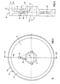
- FIG. 1 and Figure 2 in a cross-sectional view along Line II-II show a railway wheel l (monoblock wheel) that rotates in a direction of rotation 3 about an axis of rotation 5.
- the Railway wheel 1 comprises a wheel hub 7, a wheel disc 9, one Wheel rim 11 with a tread 13 and a wheel flange 15.
- In the area of the wheel disc 9 is the railway wheel 1 less wide than in the area of the wheel hub 7 and the wheel rim 11, so that transition zones 17, 19 with variable wheel width are formed. It is an inner one Transition zone 17 between the wheel hub 7 and the wheel disc 9 and an outer transition zone 19 between the wheel disc 9 and the rim 11.
- a first group radiator 21 is acoustically coupled to the tread 13. It is positioned with its insonification point approximately between the elongated end faces of the wheel disk 9 on the tread 13.
- a first sound wave 23 is irradiated by the first group radiator 21 through the tread 13 into the wheel disk 9.
- the direction of irradiation is pivoted, ie changed, in a first pivot plane 25, which is formed by the drawing plane in FIG. 1, within a pivot interval 27, at least with one component.
- the first pivot plane 25 is identical to a wheel disc plane.
- a first insonification angle ⁇ 1 (measured with respect to a radius line 24 forming an incidence perpendicular) is varied within the swivel interval 27.
- the pivot interval 27 has a width of approximately 60 ° and is approximately adjusted such that an angular range on a first side with respect to the radius line 24, specifically by a position 28 on the left-hand side in FIG. 1 on the tread 13 and by the wheel hub 7 Angular range, is scanned.
- the first insonification angle ⁇ 1 is varied from approximately 0 ° to approximately 60 °.
- insonification occurs with longitudinal polarization, with a large insonification angle ⁇ 1 with transversal polarization.
- the device points to increasing the detection probability a further first group radiator 31, the a further first sound wave 33 penetrates the railway wheel 1.
- the direction of insonation of the further first sound wave 33 is also perpendicular to the axis of rotation 5 standing first pivot plane 25 pivoted, and within a pivot interval 37 with a width of about 60 °.
- This second "vertical swivel" turns one Angular range on the opposite side of the first page Side, namely through the wheel hub 9 and through an opposite, in Figure 1 on the right-hand side with respect to the radius line 24 Position 38 on the tread 13 defined angular range, checked.
- FIG. 2 also shows how the position of a focus 41, 43 of the first sound wave 23 by phase-controlled electronic control of the first group radiator 21 varies becomes.
- the variation in focus can be done electronically Activation also by changing the active one Vibrating surface of the group radiator 31 can be reached, e.g. by switching on / off edge elements of the array.
- FIG. 2 shows a first focus 41, which results from the natural Focusing due to the finite cross-sectional area (in the radiation direction) of the first group radiator 21, thus still without electronic control.
- a second Focus 43 is activated by appropriate phase control of the first Group radiator 21 generated.
- the second focus 43 is closer to the tread 13 and has a smaller bundle cross section than the first focus 41 on. This goes hand in hand with that a second divergence angle connected to the second focus 43 ⁇ 2 is greater than the first divergence angle ⁇ 1.
- the first focus' 41 is set, the first sound wave 23 with its natural first divergence angle ⁇ 1 radiated largely undisturbed in the wheel disc 9.
- the second focus' 43 will only be part of the first Sound wave 23 radiated into the wheel disc 9, and a other part meets the surface of the outer from the inside Transition zone 19.
- FIG. 3 and FIG. 4 in a cross-sectional illustration along the line IV-IV show a second exemplary embodiment of a device according to the invention with a second group radiator 51 which, through an end face of the wheel disc 9, has a second sound wave 53 at a second insonification angle ⁇ 2 into the railway wheel 1 einschallt.
- the component of the insonification direction of the second sound wave 53 projected onto the first pivot plane 25 is pivoted in this pivot plane 25 within a pivot interval 57 with a width of approximately 60 °.
- the second insonification angle ⁇ 2 of approximately 70 ° remains approximately unchanged, which is why in this context one speaks of a "horizontal swivel" or a swivel of the squint angle.
- the divergence angle ⁇ of the second sound wave 52 remains largely unchanged and is about 5 ° to 20 °.
- the pivot interval 57 of the second group radiator 51 is adjusted such that a with respect to the radius line 24 the second group radiator 51 is arranged more symmetrically Angular range is scanned.
- the second group coach 51 radiates through the wheel disc 9 towards the inner one Transition zone 17 and in the direction of the wheel hub 7.
- Another second group radiator (not shown) can be used be present, which is positioned like the second group radiator 51 is, but instead towards the tread 13 sounds.
- the third exemplary embodiment shown in FIG Device according to the invention shows group emitters 61, 71, 81, which is an angular swivel ("vertical swivel") in a parallel oriented to the axis of rotation 5 of the railway wheel 1 perform second pivot plane 62 through the plane of the drawing 5 is formed. In the example shown it runs the second pivot plane 62 through the axis of rotation 5.
- group emitters 61, 71, 81 which is an angular swivel ("vertical swivel") in a parallel oriented to the axis of rotation 5 of the railway wheel 1 perform second pivot plane 62 through the plane of the drawing 5 is formed. In the example shown it runs the second pivot plane 62 through the axis of rotation 5.
- a third group radiator 61 emits a third sound wave 63 through the tread 13 into the outer transition zone 19 a.
- the third group radiator 61 is at that Flange 15 opposite edge of the tread 13 is arranged.
- the direction of insonification of the third sound wave 63 becomes within a swivel interval 67 with a width of pivoted about 60 °. This pivot interval 67 extends from a direction perpendicular to the axis of rotation 5 towards an inclined with respect to the axis of rotation 5 Direction.
- a fourth group radiator 71 emits a fourth sound wave 73 by means of a direction of travel of the railway wheel 1 inner side of the rim 11 in the railway wheel 1 and is as far as possible in the radial Towards the outer edge of the wheel rim 11 or the wheel flange 15 positioned.
- the fourth sound wave 73 sounds thereby in the wheel rim 11 and in the outer transition zone 19th on.
- the direction of insonation of the fourth sound wave 73 is within a swivel interval 77 with a width of varies about 60 °. This pivot interval 77 is adjusted in such a way that the direction of insonation of the fourth sound wave 73 from a direction largely parallel to the axis of rotation 5 varies towards a direction inclined to the axis of rotation 5 becomes.
- a fifth group radiator 81 emits a fifth sound wave 83 through one side of the wheel disc 9 into the railroad wheel 1 a.
- the insonation point is in the radial Direction seen from the outside immediately before the inner one Transition zone 17.
- a panning interval 87 of the direction of insonation the fifth sound wave 83 is adjusted such that the Direction of sound across the entire width of the interval of about 60 ° in the direction of the wheel hub 7.
- the third group radiator 61 and the fourth group radiator 71 are arranged on a common test carrier 100, to which the fifth group radiator 81 can also be assigned.
- the group emitters 21, 31, 51, 61, 71, 81 are with respect to the Rotation axis 5 stationary, i.e. the rotating railway wheel 1 moves with the respective coupling surface under the respective one Group spotlights 21, 31, 51, 61, 71, 81 away.
- the third group radiator 61 can be a two-dimensional one Group radiator array can be formed. He can go in the direction the axis of rotation 5 can be moved on the tread 13, so that it also extends between the extended pages the wheel disc 9, in FIG. 5 thus above the wheel disc 9 the tread 13 can be positioned (like the first group radiator 21 (see Figure 2)). From the third group spotlight 61 can then the first sound wave 23 with a swivel in the first pivot plane 25 and the third sound wave 63 irradiated with a swivel in the second swivel plane 62 without a separate first group radiator 21 would be necessary.
- the fifth group radiator 81 can be used as two-dimensional array array formed and along one side of the wheel disc 9 and possibly along one Side of the rim 11 to be movable so that it both for insonification of the second sound wave 53 with a Swivel in the first swivel plane 25 as well as for sonication the fourth sound wave 73 and / or the fifth sound wave 83 with a pivot in the second pivot plane 62 in is able without a separate second group radiator 51 would be required.
- the third group radiator 61 can be used as an array the procedure of the second variant instead of on the tread 13 be coupled to the side of the wheel disc 9.
- the fifth group radiator 81 (array) is then e.g. at a Coupled side of the rim (11).
Landscapes
- Physics & Mathematics (AREA)
- Health & Medical Sciences (AREA)
- Life Sciences & Earth Sciences (AREA)
- Chemical & Material Sciences (AREA)
- Analytical Chemistry (AREA)
- Biochemistry (AREA)
- General Health & Medical Sciences (AREA)
- General Physics & Mathematics (AREA)
- Immunology (AREA)
- Pathology (AREA)
- Investigating Or Analyzing Materials By The Use Of Ultrasonic Waves (AREA)
- Investigating Strength Of Materials By Application Of Mechanical Stress (AREA)
Description
http://www.ndt.net/article/report/df97/hintze/hintze_d.htm wurde am 10.06.1998 um 10.13 Uhr ein Fachartikel von H. Hintze, Deutsche Bahn AG, publiziert, in dem ein Verfahren zur Ultraschallprüfung von Eisenbahnrädern mit Hilfe von Oberflächenwellen, sogenannten Rayleigh-Wellen, beschrieben ist. Dabei wird mit einem elektrodynamischen Wandler auf der Basis von Permanentmagneten (sogenannter EMUS, was für elektromagnetischer Ultraschallwandler steht) eine Ultraschall-Oberflächenwelle im Radmaterial erzeugt. Die Oberflächenwelle wird durch die Lauffläche eingekoppelt und breitet sich vom Wandler ausgehend beidseitig in einem oberflächennahen Bereich entlang der Lauffläche des Rads aus. Nach einem vollständigen Umlauf um das Rad wird die Rayleigh-Welle von einem anderen elektrodynamischen Wandler wieder empfangen. Die elektrodynamischen Wandler sind - in Fahrrichtung des Eisenbahnzugs beabstandet - in den Schienen eingebaut. Der Eisenbahnzug rollt mit geringer Geschwindigkeit über die Wandler hinweg.
http://www.ndt.net/article/0698/salzb/salzb.htm wurde am 10.06.1998 um 10.10 Uhr ein Bericht über einen Vortrag auf der Jahrestagung der Deutschen Gesellschaft für zerstörungsfreie Werkstoffprüfung in Lindau vom 13. bis 15. Mai 1996, gehalten von H.-J. Salzburger und H. Hintze, veröffentlicht. In diesem Tagungsbericht ist ein Impulsecho-Prüfverfahren zur Detektion eines Risses in einem Eisenbahnrad beschrieben, bei dem von der Stirnseite des Eisenbahnrades aus mit linear polarisierten Transversalwellen senkrecht bezüglich der Stirnseite eingestrahlt wird.
- daß eine zweite Ultraschallwelle in das Eisenbahnrad eingeschallt und ein zu ihrer Einschallung vorhandener Ultraschallwandler in gleicher Weise wie der zur Einschallung der ersten Ultraschallwelle vorhandene Ultraschallwandler bewegt wird, und
- daß die Einschallrichtung der zweiten Ultraschallwelle senkrecht zur Radscheibenebene geschwenkt wird.
- FIG 1
- ein erstes Ausführungsbeispiel einer Vorrichtung nach der Erfindung zur Prüfung eines Eisenbahnrads,
- FIG 2
- einen Querschnitt entlang der Linie II-II durch die Vorrichtung und das Eisenbahnrad der Figur 1,
- FIG 3
- ein zweites Ausführungsbeispiel einer Vorrichtung nach der Erfindung zur Prüfung eines Eisenbahnrads,
- FIG 4
- einen Querschnitt entlang der Linie IV-IV durch die Vorrichtung und das Eisenbahnrad der Figur 3,
- FIG 5
- ein drittes Ausführungsbeispiel einer Vorrichtung nach der Erfindung zur Prüfung eines Eisenbahnrads.
Claims (22)
- Verfahren zur Detektion eines Risses (29A, 29B, 29C) in einem um eine Rotationsachse (5) drehbaren Eisenbahnrad (1), wobei ein zur Einschaltung einer ersten Ultraschallwelle (23, 33) vorhandener Ultraschallwandler (21, 31) relativ zum Eisenbahnrad (1) im wesentlichen kreisförmig um die Rotationsachse (5) bewegt wird, wobei die erste Ultraschallwelle (23, 33) durch die Lauffläche (13) in das Eisenbahnrad (1) eingeschallt wird, und wobei
durch den Radkranz (11) hindurch in die Radscheibe (9) eingeschallt wird, dadurch gekennzeichnet, daß die Einschallrichtung der ersten Ultraschallwelle (23, 33) in der Radscheibenebene (25) geschwenkt wird. - Verfahren zur Detektion eines Risses (29A, 29B, 29C) in einem um eine Rotationsachse (5) drehbaren Eisenbahnrad (1), wobei ein zur Einschallung einer ersten Ultraschallwelle (53) vorhandener Ultraschallwandler (51) relativ zum Eisenbahnrad (1) im wesentlichen kreisförmig um die Rotationsachse (5) bewegt wird, wobei die erste Ultraschallwelle (53) in das Eisenbahnrad (1) eingeschallt wird, und wobei,
die erste Ultraschallwelle (53) durch eine Seite der Radscheibe (9) in die Radnabe (7) eingeschallt wird,
dadurch gekennzeichnet, dass die Einschallrichtung der ersten Ultraschallwelle (53) unter einem näherungsweise unveränderten Winkel (α2) mit einer senkrecht auf der Seite der Radscheibe (9) stehenden horizontalen Ebene geschwenkt wird. - Verfahren nach einem der Ansprüche 1 oder 2,
dadurch gekennzeichnet, daß die kreisförmige Bewegung durch eine Rotation des drehbar gelagerten Eisenbahnrads (1) bei nicht um die Rotationsachse (5) rotierendem Ultraschallwandler (21, 31; 51) zustande kommt. - Verfahren nach einem der Ansprüche 1 bis 3,
dadurch gekennzeichnet,daß eine zweite Ultraschallwelle (63, 73, 83) in das Eisenbahnrad (1) eingeschallt und ein zu ihrer Einschallung vorhandener Ultraschallwandler (61, 71, 81) in gleicher Weise wie der zur Einsehallung der ersten Ultraschallwelle (23, 33) vorhandene Ultraschallwandler die 21, 31) bewegt wird, unddaß die Einschallrichtung der zweiten Ultraschallwelle (63, 73, 83) senkrecht zur Radscheibenebene (25) geschwenkt wird. - Verfahren nach Anspruch 4,
dadurch gekennzeichnet, daß zur Einschallung der ersten Ultraschallwelle (23, 33; 53) und der zweiten Ultraschallwelle (63, 73, 83) derselbe Utraschallwandler vorhanden ist. - Verfahren nach einem der Ansprüche 1 bis 5 oder 4 bis 5,
dadurch gekennzeichnet, daß die erste Ultraschallwelle (23) bzw. die zweite Ultraschallwelle elektronisch fokussiert wird. - Verfahren nach Anspruch 6,
dadurch gekennzeichnet, daß die Lage des Fokus variiert wird. - Verfahren nach einem der Ansprüche 4 bis 7,
dadurch gekennzeichnet, daß die zweite Ultraschallwelle (63) durch die Lauffläche (13) eingeschallt wird. - Verfahren nach Anspruch 8,
dadurch gekennzeichnete daß die zweite Ultraschallwelle (63) durch den Radkranz (11) hindurch in die Radscheibe (9) eingeschallt wird. - Varfahren nach einem der Ansprüche 8 oder 9,
dadurch gekennzeichnet, daß die zweite Ultraschallwelle (63) in die Übergangszone (19) zwischen Radkranz (11) und Radscheibe (9) eingeschallt wird. - Verfahren nach einem der Ansprüche 7 bis 10,
dadurch gekennzeichnet, daß die Lage des Fokus der ersten Ultraschallwelle (23) bezüglich der Lauffläche (13) derart variiert wird, daß die Schallbündelbreite der ersten Ultraschallwelle (23) in der Übergangszone (19) zwischen Radkranz (11) und Radscheibe (9) veränderlich ist. - Verfahren nach einem der Ansprüche 4 bis 7,
dadurch gekennzeichnet, daß die zweite Ultraschallwelle (83) durch eine Seite der Radscheibe (9) eingeschallt wird. - Verfahren nach Anspruch 12,
dadurch gekennzeichnet, daß die zweite Ultraschallwelle (83) in die Radnabe (7) eingeschallt wird. - Verfahren nach Anspruch 12 oder 13,
dadurch gekennzeichnet, daß die zweite Ultraschallwelle (83) in die Übergangszone (17) zwischen Radscheibe (9) und Radnabe (7) eingeschallt wird. - Verfahren nach einem der Ansprüche 4 bis 7,
dadurch gekennzeichnet, daß die zweite Ultraschallwelle (73) durch eine Seite des Radkranzes (11) eingeschallt wird. - Verfahren nach Anspruch 15,
dadurch gekennzeichnet, daß die zweite Ultraschallwelle (73) in die Übergangszone (19) zwischen Radkranz (11) und Radscheibe (9) eingeschallt wird. - Verfahren nach einem der Ansprüche 1 bis 16 oder 4 bis 16,
dadurch gekennzeichnet, daß die an unterschiedlichen Einschallstellen und/ oder mit unterschiedlichen Einschallrichtungen von der ersten ultraschallwelle bzw. der zweiten Ultraschallwelle erzeugten Empfangssignale bildgebend überlagert werden. - Vorrichtung zur Durchführung des Verfahrens nach einem der Ansprüche 1 bis 17,
gekennzeichnet durch
einen an der Lauffläche (13) akustisch ankoppelbaren ersten Ultraschall-Gruppenstrahler (21, 31) zur Einschallung einer ersten Schallwelle (23, 33) und
einen an einer Seite der Radscheibe (9) akustisch ankoppelbaren zweiten Ultraschall-Gruppenstrahler (51) zur Einschallung einer zweiten Schallwelle (53), wobei die beiden Ultraschall-Gruppenstrahler (21, 31; 51) derart auf einem gemeinsamen Prüfträger angeordnet sind, dass mit dem ersten Ultraschall-Gruppenstrahler (21, 31) durch den Radkranz (11) hindurch in die Radscheibe (9) einschallbar und seine Einschallrichtung in der Radscheibenebene (25) schwenkbar ist und dass mit dem zweiten Ultraschall-Gruppenstrahler (51) in die Radnabe einschallbar ist und seine Einschallrichtung unter einem näherungsweise unveränderten Winkel (α2) mit einer senkrecht auf der Ebene der Radscheibe (9) stehenden horizontalen Ebene schwenkbar ist, wobei die Ultraschall-Gruppenstrahler (21, 31; 51) relativ zum Eisenbahnrad (1) im wesentlichen kreisförmig um die Rotationsachse (5) des Eisenbahnrads (1) bewegbar sind. - Vorrichtung nach Anspruch 18,
dadurch gekennzeichnet, dass an dem Prüfträger ein dritter Gruppenstrahler (61) angeordnet ist, der an der Lauffläche (13) akustisch ankoppelbar und zur Einschallung einer dritten Schallwelle (63) ausgebildet ist, wobei deren Einschallrichtung in einer Schwenkebene (62) senkrecht zur Radscheibenebene (25) schwenkbar ist. - Vorrichtung nach einem der Anspruch 18 oder 19,
dadurch gekennzeichnet, dass an dem Prüfträger ein vierter Gruppenstrahler (71) angeordnet ist, der an einer Seite des Radkranzes (11) akustisch ankoppelbar und zur Einschallung einer vierten Schallwelle (73) ausgebildet ist, wobei deren Einschallrichtung in einer Schwenkebene (62) senkrecht zur Radscheibenebene (25) schwenkbar ist. - Vorrichtung nach einem der Ansprüche 18 bis 20,
dadurch gekennzeichnet, dass an dem Prüfträger ein fünfter Gruppenstrahler (81) angeordnet ist, der an einer Seite der Radscheibe (9) akustisch ankoppelbar und zur Einschallung einer fünften Schallwelle (83) ausgebildet ist, wobei deren Einschallrichtung in einer Schwenkebene (62) senkrecht zur Radscheibenebene (25) schwenkbar ist. - Vorrichtung einem der Ansprüche 18 bis 21, gekennzeichnet durch eine Auswerteeinheit, der die Empfangssignale wenigstens eines der Gruppenstrahler (21, 31, 51, 61, 71, 81) zuführbar sind und die die an unterschiedlichen Einschallstellen und/oder mit unterschiedlichen Einschallrichtungen erzeugten Empfangssignale bildgebend überlagert.
Applications Claiming Priority (3)
| Application Number | Priority Date | Filing Date | Title |
|---|---|---|---|
| DE19834587 | 1998-07-31 | ||
| DE19834587A DE19834587C1 (de) | 1998-07-31 | 1998-07-31 | Verfahren und Vorrichtung zur Detektion eines Risses in einem Eisenbahnrad |
| PCT/DE1999/002235 WO2000008459A1 (de) | 1998-07-31 | 1999-07-19 | Verfahren und vorrichtung zur detektion eines risses in einem eisenbahnrad |
Publications (2)
| Publication Number | Publication Date |
|---|---|
| EP1101105A1 EP1101105A1 (de) | 2001-05-23 |
| EP1101105B1 true EP1101105B1 (de) | 2003-09-17 |
Family
ID=7876004
Family Applications (1)
| Application Number | Title | Priority Date | Filing Date |
|---|---|---|---|
| EP99947241A Expired - Lifetime EP1101105B1 (de) | 1998-07-31 | 1999-07-19 | Verfahren und vorrichtung zur detektion eines risses in einem eisenbahnrad |
Country Status (5)
| Country | Link |
|---|---|
| EP (1) | EP1101105B1 (de) |
| AT (1) | ATE250224T1 (de) |
| DE (2) | DE19834587C1 (de) |
| TW (1) | TW510969B (de) |
| WO (1) | WO2000008459A1 (de) |
Cited By (2)
| Publication number | Priority date | Publication date | Assignee | Title |
|---|---|---|---|---|
| DE102014119056A1 (de) * | 2014-12-18 | 2016-06-23 | Ge Sensing & Inspection Technologies Gmbh | Verfahren zur Detektion eines Fehlers wie eines Risses in einer Region-of-Interest in einem um eine Rotationsachse drehbaren Eisenbahnrad sowie Vorrichtung hierzu |
| DE102015225780A1 (de) | 2015-12-17 | 2017-06-22 | Arxes-Tolina Gmbh | Ultraschallprüfverfahren und Ultraschallprüfvorrichtung zum Prüfen eines Rotationselementes |
Families Citing this family (23)
| Publication number | Priority date | Publication date | Assignee | Title |
|---|---|---|---|---|
| US6789427B2 (en) | 2002-09-16 | 2004-09-14 | General Electric Company | Phased array ultrasonic inspection method for industrial applications |
| DE10336042C5 (de) * | 2003-08-01 | 2011-01-20 | Windhoff Bahn- Und Anlagentechnik Gmbh | Anordnung und Verfahren zum Prüfen von Rädern eines Schienenfahrzeugs |
| EP2843401A1 (de) | 2013-08-30 | 2015-03-04 | Nederlandse Organisatie voor toegepast -natuurwetenschappelijk onderzoek TNO | System und Verfahren zur Fehlererkennung |
| EP2886414B1 (de) | 2013-12-20 | 2019-05-08 | Schweizerische Bundesbahnen SBB | Transportvorrichtung für Radsätze und Drehgestelle |
| EP2982794A1 (de) | 2014-08-06 | 2016-02-10 | Schweizerische Bundesbahnen SBB | Vorrichtung zur Führung von Schienenfahrzeugen |
| CN104391038B (zh) * | 2014-11-05 | 2017-01-18 | 江阴市恒润环锻有限公司 | 指针式风电法兰端面无损检测装置 |
| US10349491B2 (en) | 2015-01-19 | 2019-07-09 | Tetra Tech, Inc. | Light emission power control apparatus and method |
| CA2892885C (en) | 2015-02-20 | 2020-07-28 | Tetra Tech, Inc. | 3d track assessment system and method |
| DE102015108720A1 (de) | 2015-06-02 | 2016-07-14 | Areva Gmbh | Ultraschall-Prüfvorrichtung und Verfahren zur zerstörungsfreien Prüfung eines Rades und einer Radscheibe |
| EP3320334B1 (de) * | 2015-07-07 | 2022-08-31 | General Electric Company | Verfahren und vorrichtung zur inspektion eines eisenbahnrades mit gruppenstrahlern |
| CN105277622B (zh) * | 2015-12-01 | 2018-03-23 | 西南交通大学 | 一种列车轮对探伤检测方法及装置 |
| CN105548185B (zh) * | 2016-01-08 | 2018-12-11 | 浙江科技学院 | 基于机器视觉的汽车轮毂螺孔识别方法、遮盖方法及系统 |
| DE102016002842A1 (de) | 2016-03-03 | 2017-09-07 | Frank Christophè Baumann | Ultraschallsystem zur Abtastung von Rädern von Eisenbahnwagons |
| CA3049267C (en) | 2017-02-22 | 2023-03-14 | Tetra Tech, Inc. | Broken wheel detection system |
| CN111344565A (zh) * | 2017-10-12 | 2020-06-26 | 通用电气石油和天然气有限责任公司 | 具有耦接验证的超声测试检查 |
| US10730538B2 (en) | 2018-06-01 | 2020-08-04 | Tetra Tech, Inc. | Apparatus and method for calculating plate cut and rail seat abrasion based on measurements only of rail head elevation and crosstie surface elevation |
| US10625760B2 (en) | 2018-06-01 | 2020-04-21 | Tetra Tech, Inc. | Apparatus and method for calculating wooden crosstie plate cut measurements and rail seat abrasion measurements based on rail head height |
| US10807623B2 (en) | 2018-06-01 | 2020-10-20 | Tetra Tech, Inc. | Apparatus and method for gathering data from sensors oriented at an oblique angle relative to a railway track |
| US11377130B2 (en) | 2018-06-01 | 2022-07-05 | Tetra Tech, Inc. | Autonomous track assessment system |
| JP7127572B2 (ja) * | 2019-02-20 | 2022-08-30 | 日本製鉄株式会社 | 鉄道車両用車輪の転動による疲労き裂進展抑制方法 |
| AU2020273465C1 (en) | 2019-05-16 | 2026-02-05 | Tetra Tech, Inc. | System and method for generating and interpreting point clouds of a rail corridor along a survey path |
| CN111157263B (zh) * | 2019-12-31 | 2021-09-03 | 同济大学 | 一种铁道车辆的轮对试验台 |
| CN111879537A (zh) * | 2020-07-31 | 2020-11-03 | 成都盛锴科技有限公司 | 一种分离式车轮探伤系统及其方法 |
Family Cites Families (11)
| Publication number | Priority date | Publication date | Assignee | Title |
|---|---|---|---|---|
| US4180790A (en) * | 1977-12-27 | 1979-12-25 | General Electric Company | Dynamic array aperture and focus control for ultrasonic imaging systems |
| DE3377530D1 (en) * | 1982-03-20 | 1988-09-01 | Fujitsu Ltd | Ultrasonic sector-scan probe |
| DE3236218A1 (de) * | 1982-09-30 | 1984-04-05 | Dietmar 5840 Schwerte Demuth | Verfahren und vorrichtung zur digitalen ansteuerung einer verzoegerungskette fuer ein ultraschall-geraet |
| DE3241200A1 (de) * | 1982-11-08 | 1984-05-10 | Siemens AG, 1000 Berlin und 8000 München | Ultraschallwandleranordnung |
| DE3301981A1 (de) * | 1983-01-21 | 1984-07-26 | Siemens AG, 1000 Berlin und 8000 München | Ultraschallabbildungssystem |
| WO1990013814A1 (en) * | 1989-05-01 | 1990-11-15 | Hamersley Iron Pty. Limited | Ultrasonic wheel testing |
| FR2689242B1 (fr) * | 1992-03-30 | 1994-07-01 | Valdunes | Dispositif de mesure automatique des contraintes residuelles dans la jante d'une roue d'un essieu, monte de chemin de fer. |
| DE4220444A1 (de) * | 1992-06-23 | 1994-01-05 | Krautkraemer Gmbh | Verfahren zur Längs-, Quer- und Schrägfehlerprüfung mittels Ultraschall von Werkstücken nach dem Impuls-Echo-Verfahren |
| DE4404356A1 (de) * | 1994-02-11 | 1995-08-17 | Hegenscheidt Gmbh Wilhelm | Verfahren zur zerstörungsfreien Prüfung von Eisenbahnrädern |
| US5533401A (en) * | 1994-05-12 | 1996-07-09 | General Electric Company | Multizone ultrasonic inspection method and apparatus |
| HUP9602626A3 (en) * | 1996-09-25 | 1999-04-28 | Szekeres Peter | Rotation display |
-
1998
- 1998-07-31 DE DE19834587A patent/DE19834587C1/de not_active Expired - Fee Related
-
1999
- 1999-06-29 TW TW088110971A patent/TW510969B/zh active
- 1999-07-19 DE DE59907036T patent/DE59907036D1/de not_active Expired - Lifetime
- 1999-07-19 WO PCT/DE1999/002235 patent/WO2000008459A1/de not_active Ceased
- 1999-07-19 EP EP99947241A patent/EP1101105B1/de not_active Expired - Lifetime
- 1999-07-19 AT AT99947241T patent/ATE250224T1/de active
Cited By (3)
| Publication number | Priority date | Publication date | Assignee | Title |
|---|---|---|---|---|
| DE102014119056A1 (de) * | 2014-12-18 | 2016-06-23 | Ge Sensing & Inspection Technologies Gmbh | Verfahren zur Detektion eines Fehlers wie eines Risses in einer Region-of-Interest in einem um eine Rotationsachse drehbaren Eisenbahnrad sowie Vorrichtung hierzu |
| CN107278269A (zh) * | 2014-12-18 | 2017-10-20 | Ge传感与检测技术有限公司 | 用于围绕轴可旋转的火车轮的感兴趣区域中的缺陷的超声检测的方法及其装置 |
| DE102015225780A1 (de) | 2015-12-17 | 2017-06-22 | Arxes-Tolina Gmbh | Ultraschallprüfverfahren und Ultraschallprüfvorrichtung zum Prüfen eines Rotationselementes |
Also Published As
| Publication number | Publication date |
|---|---|
| ATE250224T1 (de) | 2003-10-15 |
| DE19834587C1 (de) | 2000-04-20 |
| DE59907036D1 (de) | 2003-10-23 |
| TW510969B (en) | 2002-11-21 |
| WO2000008459A1 (de) | 2000-02-17 |
| EP1101105A1 (de) | 2001-05-23 |
Similar Documents
| Publication | Publication Date | Title |
|---|---|---|
| EP1101105B1 (de) | Verfahren und vorrichtung zur detektion eines risses in einem eisenbahnrad | |
| EP1098803B1 (de) | Verfahren und vorrichtung zum prüfen eines eisenbahnrads | |
| EP0685068B1 (de) | Ultraschall-prüfvorrichtung für schweissnähte bei rohren, blechen und behältern | |
| DE68916204T2 (de) | Verfahren und Vorrichtung zur genauen Einstellung eines Teiles, das quer entlang einer Schiene versetzt ist. | |
| DE102007058043B4 (de) | Vorrichtung und Verfahren zur zerstörungsfreien Prüfung von Rohrleitungen | |
| DE102009047317A1 (de) | Verfahren und Vorrichtung zur Ultraschallprüfung | |
| EP1333277A2 (de) | Verfahren und Vorrichtung zum Untersuchen von Rohrleitungen mit Ultraschall-Gruppenstrahlern | |
| DE2255983A1 (de) | Verfahren und vorrichtung zum pruefen und untersuchen von raedern und zum feststellen von fehlern an den raedern | |
| DE102019106427B4 (de) | Wandler und Wandleranordnung für Ultraschall-Prüfkopfsysteme, Ultraschall-Prüfkopfsystem und Prüfverfahren | |
| EP1099113A1 (de) | Ultraschall-prüfeinrichtung | |
| WO2001098769A1 (de) | Vorrichtung und verfahren zur prüfung eines eisenbahnrades | |
| EP0126383B1 (de) | Verfahren zur Ultraschallprüfung von auf Wellen aufgeschrumpften Scheibenkörpern im Bereich der Schrumpfsitze und Einrichtung zur Durchführung des Verfahrens | |
| DE102012112121A1 (de) | Verfahren und Vorrichtung zur zerstörungsfreien Prüfung eines rotationssymmetrischen Werkstücks, welches Abschnitte verschiedener Durchmesser aufweist | |
| EP1238270B1 (de) | Verfahren zur ultraschallprüfung einer schweissnaht eines geschweissten turbinenläufers | |
| DE2129110A1 (de) | Verfahren zum Überprüfen von metallischen Schweißungen | |
| DE10062722A1 (de) | Verfahren und Vorrichtung zur Ultraschallprüfung von Überlappschweissnähten zwischen einem ersten Blech und einem zweiten Blech nach dem Impulsverfahren | |
| EP1097374A2 (de) | Verfahren und vorrichtungen zur detektion eines risses in einem eisenbahnrad | |
| DE102015108720A1 (de) | Ultraschall-Prüfvorrichtung und Verfahren zur zerstörungsfreien Prüfung eines Rades und einer Radscheibe | |
| DE10052045C2 (de) | Vorrichtung und Verfahren zur Prüfung eines Eisenbahnrades | |
| DE19943215C2 (de) | Verfahren und Vorrichtung zur Detektion eines Fehlers mittels Ultraschall | |
| DE102012112120B4 (de) | Verfahren und Vorrichtung zur oberflächennahen zerstörungsfreien Prüfung eines rotationssymmetrischen Werkstücks mit abschnittsweise wechselndem Durchmesser mittels Ultraschall | |
| DE4404356A1 (de) | Verfahren zur zerstörungsfreien Prüfung von Eisenbahnrädern | |
| DE1812764C3 (de) | Vorrichtung zur zerstörungsfreien Werkstoffüberprüfung an Rädern von Eisenbahnfahrzeugen | |
| EP0766822A1 (de) | Vorrichtung zum messen von unregelmässigkeiten in behälterinnenwänden mit ultraschall | |
| EP4382904B1 (de) | Prüfkopfsonde zur ultraschall-prüfung von radsatzwellen mit innenliegender längsbohrung |
Legal Events
| Date | Code | Title | Description |
|---|---|---|---|
| PUAI | Public reference made under article 153(3) epc to a published international application that has entered the european phase |
Free format text: ORIGINAL CODE: 0009012 |
|
| 17P | Request for examination filed |
Effective date: 20010112 |
|
| AK | Designated contracting states |
Kind code of ref document: A1 Designated state(s): AT BE CH CY DE DK ES FI FR GB GR IE IT LI LU MC NL PT SE |
|
| RAP1 | Party data changed (applicant data changed or rights of an application transferred) |
Owner name: INTELLIGENDT SYSTEMS & SERVICES GMBH & CO KG |
|
| RAP1 | Party data changed (applicant data changed or rights of an application transferred) |
Owner name: INTELLIGENDT SYSTEMS & SERVICES GMBH & CO KG Owner name: SIEMENS AKTIENGESELLSCHAFT |
|
| 17Q | First examination report despatched |
Effective date: 20020227 |
|
| GRAH | Despatch of communication of intention to grant a patent |
Free format text: ORIGINAL CODE: EPIDOS IGRA |
|
| GRAS | Grant fee paid |
Free format text: ORIGINAL CODE: EPIDOSNIGR3 |
|
| GRAA | (expected) grant |
Free format text: ORIGINAL CODE: 0009210 |
|
| AK | Designated contracting states |
Kind code of ref document: B1 Designated state(s): AT BE CH CY DE DK ES FI FR GB GR IE IT LI LU MC NL PT SE |
|
| PG25 | Lapsed in a contracting state [announced via postgrant information from national office to epo] |
Ref country code: NL Free format text: LAPSE BECAUSE OF FAILURE TO SUBMIT A TRANSLATION OF THE DESCRIPTION OR TO PAY THE FEE WITHIN THE PRESCRIBED TIME-LIMIT Effective date: 20030917 Ref country code: IE Free format text: LAPSE BECAUSE OF FAILURE TO SUBMIT A TRANSLATION OF THE DESCRIPTION OR TO PAY THE FEE WITHIN THE PRESCRIBED TIME-LIMIT Effective date: 20030917 Ref country code: GB Free format text: LAPSE BECAUSE OF FAILURE TO SUBMIT A TRANSLATION OF THE DESCRIPTION OR TO PAY THE FEE WITHIN THE PRESCRIBED TIME-LIMIT Effective date: 20030917 Ref country code: FI Free format text: LAPSE BECAUSE OF FAILURE TO SUBMIT A TRANSLATION OF THE DESCRIPTION OR TO PAY THE FEE WITHIN THE PRESCRIBED TIME-LIMIT Effective date: 20030917 Ref country code: CY Free format text: LAPSE BECAUSE OF FAILURE TO SUBMIT A TRANSLATION OF THE DESCRIPTION OR TO PAY THE FEE WITHIN THE PRESCRIBED TIME-LIMIT Effective date: 20030917 |
|
| REG | Reference to a national code |
Ref country code: GB Ref legal event code: FG4D Free format text: NOT ENGLISH |
|
| REG | Reference to a national code |
Ref country code: CH Ref legal event code: NV Representative=s name: SIEMENS SCHWEIZ AG Ref country code: CH Ref legal event code: EP |
|
| REF | Corresponds to: |
Ref document number: 59907036 Country of ref document: DE Date of ref document: 20031023 Kind code of ref document: P |
|
| REG | Reference to a national code |
Ref country code: IE Ref legal event code: FG4D Free format text: GERMAN |
|
| PG25 | Lapsed in a contracting state [announced via postgrant information from national office to epo] |
Ref country code: SE Free format text: LAPSE BECAUSE OF FAILURE TO SUBMIT A TRANSLATION OF THE DESCRIPTION OR TO PAY THE FEE WITHIN THE PRESCRIBED TIME-LIMIT Effective date: 20031217 Ref country code: GR Free format text: LAPSE BECAUSE OF FAILURE TO SUBMIT A TRANSLATION OF THE DESCRIPTION OR TO PAY THE FEE WITHIN THE PRESCRIBED TIME-LIMIT Effective date: 20031217 Ref country code: DK Free format text: LAPSE BECAUSE OF FAILURE TO SUBMIT A TRANSLATION OF THE DESCRIPTION OR TO PAY THE FEE WITHIN THE PRESCRIBED TIME-LIMIT Effective date: 20031217 |
|
| PG25 | Lapsed in a contracting state [announced via postgrant information from national office to epo] |
Ref country code: PT Free format text: LAPSE BECAUSE OF FAILURE TO SUBMIT A TRANSLATION OF THE DESCRIPTION OR TO PAY THE FEE WITHIN THE PRESCRIBED TIME-LIMIT Effective date: 20031226 |
|
| PG25 | Lapsed in a contracting state [announced via postgrant information from national office to epo] |
Ref country code: ES Free format text: LAPSE BECAUSE OF FAILURE TO SUBMIT A TRANSLATION OF THE DESCRIPTION OR TO PAY THE FEE WITHIN THE PRESCRIBED TIME-LIMIT Effective date: 20031228 |
|
| NLV1 | Nl: lapsed or annulled due to failure to fulfill the requirements of art. 29p and 29m of the patents act | ||
| GBV | Gb: ep patent (uk) treated as always having been void in accordance with gb section 77(7)/1977 [no translation filed] |
Effective date: 20030917 |
|
| REG | Reference to a national code |
Ref country code: IE Ref legal event code: FD4D |
|
| ET | Fr: translation filed | ||
| PG25 | Lapsed in a contracting state [announced via postgrant information from national office to epo] |
Ref country code: LU Free format text: LAPSE BECAUSE OF NON-PAYMENT OF DUE FEES Effective date: 20040719 |
|
| PLBE | No opposition filed within time limit |
Free format text: ORIGINAL CODE: 0009261 |
|
| STAA | Information on the status of an ep patent application or granted ep patent |
Free format text: STATUS: NO OPPOSITION FILED WITHIN TIME LIMIT |
|
| PG25 | Lapsed in a contracting state [announced via postgrant information from national office to epo] |
Ref country code: MC Free format text: LAPSE BECAUSE OF NON-PAYMENT OF DUE FEES Effective date: 20040731 Ref country code: BE Free format text: LAPSE BECAUSE OF NON-PAYMENT OF DUE FEES Effective date: 20040731 |
|
| 26N | No opposition filed |
Effective date: 20040618 |
|
| BERE | Be: lapsed |
Owner name: *INTELLIGENDT SYSTEMS & SERVICES G.M.B.H. & CO. K. Effective date: 20040731 Owner name: *SIEMENS A.G. Effective date: 20040731 |
|
| BERE | Be: lapsed |
Owner name: *INTELLIGENDT SYSTEMS & SERVICES G.M.B.H. & CO. K. Effective date: 20040731 Owner name: *SIEMENS A.G. Effective date: 20040731 |
|
| REG | Reference to a national code |
Ref country code: CH Ref legal event code: PCAR Free format text: SIEMENS SCHWEIZ AG;INTELLECTUAL PROPERTY FREILAGERSTRASSE 40;8047 ZUERICH (CH) |
|
| REG | Reference to a national code |
Ref country code: CH Ref legal event code: PFA Owner name: SIEMENS AKTIENGESELLSCHAFT Free format text: SIEMENS AKTIENGESELLSCHAFT#WITTELSBACHERPLATZ 2#80333 MUENCHEN (DE) $ INTELLIGENDT SYSTEMS & SERVICES GMBH & CO. KG#FREYESLEBENSTRASSE 1#91058 ERLANGEN (DE) -TRANSFER TO- SIEMENS AKTIENGESELLSCHAFT#WITTELSBACHERPLATZ 2#80333 MUENCHEN (DE) $ INTELLIGENDT SYSTEMS & SERVICES GMBH#PAUL-GOSSEN-STRASSE 100#91052 ERLANGEN (DE) |
|
| REG | Reference to a national code |
Ref country code: CH Ref legal event code: NV Representative=s name: E. BLUM & CO. AG PATENT- UND MARKENANWAELTE VSP |
|
| REG | Reference to a national code |
Ref country code: FR Ref legal event code: TQ Ref country code: FR Ref legal event code: CD |
|
| REG | Reference to a national code |
Ref country code: CH Ref legal event code: PUEA Owner name: NTELLIGENDT SYSTEMS & SERVICES GMBH Free format text: SIEMENS AKTIENGESELLSCHAFT#WITTELSBACHERPLATZ 2#80333 MUENCHEN (DE) $ INTELLIGENDT SYSTEMS & SERVICES GMBH#PAUL-GOSSEN-STRASSE 100#91052 ERLANGEN (DE) -TRANSFER TO- INTELLIGENDT SYSTEMS & SERVICES GMBH#PAUL-GOSSEN-STRASSE 100#91052 ERLANGEN (DE) |
|
| REG | Reference to a national code |
Ref country code: FR Ref legal event code: TP |
|
| REG | Reference to a national code |
Ref country code: DE Ref legal event code: R082 Ref document number: 59907036 Country of ref document: DE Representative=s name: MEISSNER BOLTE PATENTANWAELTE RECHTSANWAELTE P, DE Ref country code: DE Ref legal event code: R082 Ref document number: 59907036 Country of ref document: DE Representative=s name: MEISSNER, BOLTE & PARTNER GBR, DE Ref country code: DE Ref legal event code: R082 Ref document number: 59907036 Country of ref document: DE Representative=s name: MEISSNER BOLTE & PARTNER GBR, DE |
|
| REG | Reference to a national code |
Ref country code: DE Ref legal event code: R082 Ref document number: 59907036 Country of ref document: DE Representative=s name: MEISSNER BOLTE PATENTANWAELTE RECHTSANWAELTE P, DE Ref country code: DE Ref legal event code: R082 Ref document number: 59907036 Country of ref document: DE Representative=s name: MEISSNER, BOLTE & PARTNER GBR, DE Ref country code: DE Ref legal event code: R081 Ref document number: 59907036 Country of ref document: DE Owner name: AREVA GMBH, DE Free format text: FORMER OWNER: INTELLIGENDT SYSTEMS & SERVICES GMBH, 91052 ERLANGEN, DE |
|
| REG | Reference to a national code |
Ref country code: FR Ref legal event code: PLFP Year of fee payment: 18 |
|
| PGFP | Annual fee paid to national office [announced via postgrant information from national office to epo] |
Ref country code: IT Payment date: 20160721 Year of fee payment: 18 Ref country code: CH Payment date: 20160726 Year of fee payment: 18 |
|
| PGFP | Annual fee paid to national office [announced via postgrant information from national office to epo] |
Ref country code: FR Payment date: 20160722 Year of fee payment: 18 Ref country code: AT Payment date: 20160720 Year of fee payment: 18 |
|
| REG | Reference to a national code |
Ref country code: CH Ref legal event code: PL |
|
| REG | Reference to a national code |
Ref country code: AT Ref legal event code: MM01 Ref document number: 250224 Country of ref document: AT Kind code of ref document: T Effective date: 20170719 |
|
| REG | Reference to a national code |
Ref country code: FR Ref legal event code: ST Effective date: 20180330 |
|
| PG25 | Lapsed in a contracting state [announced via postgrant information from national office to epo] |
Ref country code: LI Free format text: LAPSE BECAUSE OF NON-PAYMENT OF DUE FEES Effective date: 20170731 Ref country code: CH Free format text: LAPSE BECAUSE OF NON-PAYMENT OF DUE FEES Effective date: 20170731 |
|
| PG25 | Lapsed in a contracting state [announced via postgrant information from national office to epo] |
Ref country code: FR Free format text: LAPSE BECAUSE OF NON-PAYMENT OF DUE FEES Effective date: 20170731 Ref country code: AT Free format text: LAPSE BECAUSE OF NON-PAYMENT OF DUE FEES Effective date: 20170719 |
|
| PG25 | Lapsed in a contracting state [announced via postgrant information from national office to epo] |
Ref country code: IT Free format text: LAPSE BECAUSE OF NON-PAYMENT OF DUE FEES Effective date: 20170719 |
|
| PGFP | Annual fee paid to national office [announced via postgrant information from national office to epo] |
Ref country code: DE Payment date: 20180725 Year of fee payment: 20 |
|
| REG | Reference to a national code |
Ref country code: DE Ref legal event code: R071 Ref document number: 59907036 Country of ref document: DE |