EP1101892B1 - Mécanisme de condamnation-décondamnation d'une porte de véhicule automobile - Google Patents
Mécanisme de condamnation-décondamnation d'une porte de véhicule automobile Download PDFInfo
- Publication number
- EP1101892B1 EP1101892B1 EP00403049A EP00403049A EP1101892B1 EP 1101892 B1 EP1101892 B1 EP 1101892B1 EP 00403049 A EP00403049 A EP 00403049A EP 00403049 A EP00403049 A EP 00403049A EP 1101892 B1 EP1101892 B1 EP 1101892B1
- Authority
- EP
- European Patent Office
- Prior art keywords
- lock
- door
- lever
- housing
- rotation
- Prior art date
- Legal status (The legal status is an assumption and is not a legal conclusion. Google has not performed a legal analysis and makes no representation as to the accuracy of the status listed.)
- Expired - Lifetime
Links
- 230000007246 mechanism Effects 0.000 title claims description 19
- 210000000056 organ Anatomy 0.000 description 7
- 239000000428 dust Substances 0.000 description 5
- 238000007789 sealing Methods 0.000 description 2
- 238000012423 maintenance Methods 0.000 description 1
Images


Classifications
-
- E—FIXED CONSTRUCTIONS
- E05—LOCKS; KEYS; WINDOW OR DOOR FITTINGS; SAFES
- E05B—LOCKS; ACCESSORIES THEREFOR; HANDCUFFS
- E05B85/00—Details of vehicle locks not provided for in groups E05B77/00 - E05B83/00
- E05B85/10—Handles
-
- E—FIXED CONSTRUCTIONS
- E05—LOCKS; KEYS; WINDOW OR DOOR FITTINGS; SAFES
- E05B—LOCKS; ACCESSORIES THEREFOR; HANDCUFFS
- E05B77/00—Vehicle locks characterised by special functions or purposes
- E05B77/34—Protection against weather or dirt, e.g. against water ingress
-
- E—FIXED CONSTRUCTIONS
- E05—LOCKS; KEYS; WINDOW OR DOOR FITTINGS; SAFES
- E05B—LOCKS; ACCESSORIES THEREFOR; HANDCUFFS
- E05B85/00—Details of vehicle locks not provided for in groups E05B77/00 - E05B83/00
- E05B85/10—Handles
- E05B85/12—Inner door handles
- E05B85/13—Inner door handles with a locking knob forming part of the inside door handle unit
Definitions
- the present invention relates to a mechanism for condemnation-unlocking of a motor vehicle door.
- Motor vehicle doors have generally each a unlocking mechanism comprising a lock of the door lock and an organ maneuver supported by a box integral with the structure from this door.
- the operating member is pivotally mounted on the housing by means of an axis of rotation and is connected to said lock by a linking assembly.
- the link assembly is formed by an actuating rod having a first end is connected to the lock and whose second end is connected to the actuating member by a fastener.
- the tilting of this actuator around its axis of rotation causes the conviction or the decon- door.
- This door is ensured by a pallet which is itself pivotally mounted on an axis of rotation.
- the link assembly is disposed in an area subject to dust, while the actuator is disposed in a clean area that is not subject to the dust and it turns out that in most mechanisms used so far, the tightness between the two areas is not effectively ensured for all positions of this maneuvering organ.
- US-A-5,613,717 discloses a mechanism condemnation-unlocking of a motor vehicle door, of the type comprising a locking lock of the door and a box integral with the structure of this door and supporting an actuator pivotally mounted on the housing by means of an axis of rotation and connected to said lock by a linking assembly.
- the connection set is formed by an actuating rod connected to the lock and at a first end of a lever pivotally mounted on the axis of rotation and whose second end passes through the housing by an opening and is connected to the actuating member by an assembly by interlocking.
- the invention aims to provide a solution the problems mentioned above by proposing a mechanism for locking-unlocking a vehicle door simple, economical and adaptable to any type of vehicle door.
- the subject of the invention is therefore a mechanism for condemnation-unlocking of a motor vehicle door, of the type comprising a locking lock of the door and a box integral with the structure of this door supporting an actuator pivotally mounted on the housing by means of an axis of rotation and connected to said lock by a link set, where the set connection is formed by a connected actuating rod, on the one hand, at the lock and, on the other hand, at a first end of a lever pivoted on the axis of rotation and whose second end passes through the housing by an opening and is connected to an actuator by a interlocking assembly and where the outer edge of the end of the actuator connected to the lever is in permanent contact with the edges of the housing opening for all positions of said actuator
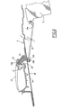
- FIG. 1 schematically shown the inner face of a door and for example a rear door 1 of a motor vehicle, equipped near its end rear of a lock lock 2 of said door 1.
- This door 1 is also equipped with a mechanism condemnation-unlocking which comprises a housing designated as a whole by reference 10 and which supports an actuator 11 to ensure the conviction or the unlocking of the door 1 and a pallet 12 opening of said door 1 connected itself by a linkage conventional, not shown, to the lock 2.
- the pallet 12 is biased against the housing 10 by a spring of reminder 12a.
- the organ 11 is pivotally mounted on the housing 10 to by means of an axis of rotation 13 and is connected to the lock 2 by a connecting assembly which is formed by a rod actuator 14 and a lever 15.
- the actuating rod 14 has a first end 14a connected to the lock 2 and a second end 14b connected to one end 15a of the lever 15 while the other end 15b of said lever 15 is pivotally mounted on the axis of rotation 13.
- the second end 15b of the lever 15 passes through the housing 10 through an opening 16 and is connected to the body maneuver 11 by an assembly by interlocking.
- the assembly by interlocking between the lever 15 and the operating member 11 is formed by a tenon 20 formed at the end 15b lever 15 and a mortise 21 formed at the end corresponding to said operating member 11, the tenon 20 being locked in the mortise 21 by the axis of rotation 13 which passes through the lever 15 and the actuator 11.
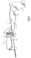
- the actuator 11 moves from the position of condemnation of the door 1, shown in FIG. 2, at the unlocking position of said door 1, shown in FIG. FIG. 3, by tilting about the axis 13.
- the operating member 11 actuates the lock 2 via the lever 15 and the actuating rod 14.
- the housing 10 is fixed on a lining the door and the actuating member 11 and the end 15b of the lever 15 are arranged outside of the lining, ie in a clean zone that is not not subject to dust, while the other end 15a lever 15 and connecting linkage 14 are located between the inner face of the lining and the panel external door 1, ie in an area subject to dust.
- the outer edge of the end of the actuating member 11 is in constant contact with the edges of the opening 16 housing 10 for all positions of said actuator, as shown in Figs. 2 to 4.
- the axis of rotation 13 is substantially orthogonal to the longitudinal direction of the actuating rod 14 and this axis of rotation 13 also supports the pallet 12 of opening command of the door 1 via the lock 2.
- the assembly of the various elements composing the condemnation-unlocking mechanism is realized from the following way.
- the return spring 12a of the pallet 12 is positioned in said pallet and this set is then placed in the housing 10.
- the actuator 11 is put in place in the opening 16 formed on the housing 10 and the lever 15 is put in place by introducing the tenon 20 of this lever 15 in the mortise 21 of the body of maneuver 11.
- This actuator 11 and the lever 15 are integral with each other because the lever 15 is maintained tightly in the actuator 11 and that this organ operating maneuver 11 is maintained in the opening 16.
- This pre-maintenance makes it possible to simplify the means assembly.
- the locking-unlocking mechanism according to the invention has the advantage of sealing effective at the level of the operating organ of this mechanism and this for all the positions of said operating member.
Landscapes
- Lock And Its Accessories (AREA)
- Power-Operated Mechanisms For Wings (AREA)
Description
- l'assemblage par emboítement entre le levier et l'organe de manoeuvre est formé par un tenon ménagé à l'extrémité dudit levier et par une mortaise ménagée à l'extrémité correspondante dudit organe de manoeuvre,
- l'axe de rotation est sensiblement et orthogonal à la direction longitudinale de la tringle d'actionnement,
- l'axe de rotation supporte une palette de commande de la serrure.
- la Fig. 1 est une vue schématique avec arrachement partiel de la face interne d'une porte d'un véhicule automobile munie d'un mécanisme de condamnation-décondamnation conforme à l'invention,
- la Fig. 2 est une vue schématique en coupe selon la ligne 2-2 de la Fig. 1 montrant le mécanisme en position de condamnation,
- la Fig. 3 est une vue en coupe selon la ligne 2-2 de la Fig. 1 montrant le mécanisme en position de décondamnation,
- la Fig. 4 est une vue schématique en coupe selon la ligne 4-4 de la Fig. 1.
Claims (4)
- Mécanisme de condamnation-décondamnation d'une porte (1) de véhicule automobile, du type comprenant une serrure de verrouillage (2) de la porte (1) et un boítier (10) solidaire de la structure de cette porte (1) et supportant un organe de manoeuvre (11) monté pivotant sur le boítier (10) au moyen d'un axe de rotation (13) et raccordé à ladite serrure (2) par un ensemble de liaison, où l'ensemble de liaison est formé par une tringle d'actionnement (14) reliée, d'une part, à la serrure (2) et, d'autre part, à une première extrémité (15a) d'un levier (15) monté pivotant sur l'axe de rotation (13) et dont une seconde extrémité (15b) traverse le boítier (10) par une ouverture (16) et est reliée à l'organe de manoeuvre (11) par un assemblage (20, 21) par emboítement, caractérisé en ce que le bord externe de l'extrémité de l'organe de manoeuvre (11) relié au levier (15) est en contact permanent avec les rebords de l'ouverture (16) du boítier (10) pour toutes les positions dudit organe de manoeuvre (11).
- Mécanisme selon la revendication 1, caractérisé en ce que l'assemblage par emboítement entre le levier (15) et l'organe de manoeuvre (11) est formé par un tenon (20) ménagé à l'extrémité (15b) dudit levier (15) et par une mortaise (21) ménagée à l'extrémité correspondante dudit organe de manoeuvre (11).
- Mécanisme selon la revendication 1, caractérisé en ce que l'axe de rotation (13) est sensiblement orthogonal à la direction longitudinale de la tringle d'actionnement (14).
- Mécanisme selon la revendication 1, caractérisé en ce que l'axe de rotation (13) supporte une palette (12) de commande de la serrure (2).
Applications Claiming Priority (2)
| Application Number | Priority Date | Filing Date | Title |
|---|---|---|---|
| FR9914512 | 1999-11-18 | ||
| FR9914512A FR2801335B1 (fr) | 1999-11-18 | 1999-11-18 | Mecanisme de condamnation-decondamnation d'une porte de vehicule automobile |
Publications (2)
| Publication Number | Publication Date |
|---|---|
| EP1101892A1 EP1101892A1 (fr) | 2001-05-23 |
| EP1101892B1 true EP1101892B1 (fr) | 2005-01-26 |
Family
ID=9552261
Family Applications (1)
| Application Number | Title | Priority Date | Filing Date |
|---|---|---|---|
| EP00403049A Expired - Lifetime EP1101892B1 (fr) | 1999-11-18 | 2000-11-02 | Mécanisme de condamnation-décondamnation d'une porte de véhicule automobile |
Country Status (5)
| Country | Link |
|---|---|
| EP (1) | EP1101892B1 (fr) |
| AT (1) | ATE288010T1 (fr) |
| DE (1) | DE60017682T2 (fr) |
| ES (1) | ES2232396T3 (fr) |
| FR (1) | FR2801335B1 (fr) |
Families Citing this family (1)
| Publication number | Priority date | Publication date | Assignee | Title |
|---|---|---|---|---|
| JP4372780B2 (ja) * | 2006-09-26 | 2009-11-25 | 本田技研工業株式会社 | 車両のロックノブ構造 |
Family Cites Families (4)
| Publication number | Priority date | Publication date | Assignee | Title |
|---|---|---|---|---|
| FR2359457A1 (fr) * | 1976-07-23 | 1978-02-17 | Renault | Dispositif a poignee pour l'ouverture et la condamnation interieures, notamment d'une porte de vehicule automobile |
| DE9102488U1 (de) * | 1991-02-28 | 1991-06-13 | Lignotock GmbH, 6443 Sontra | Handhebel zur Türschloßinnenentriegelung bei Kraftfahrzeugen |
| SE502936C2 (sv) * | 1991-11-04 | 1996-02-26 | Itw Fixfast Ab | Metod för montering av en dörrhandtagsenhet, och dörrhandtagsenhet |
| KR100204959B1 (ko) * | 1994-12-30 | 1999-06-15 | 전성원 | 자동차용 도어 개폐 장치 |
-
1999
- 1999-11-18 FR FR9914512A patent/FR2801335B1/fr not_active Expired - Fee Related
-
2000
- 2000-11-02 ES ES00403049T patent/ES2232396T3/es not_active Expired - Lifetime
- 2000-11-02 DE DE60017682T patent/DE60017682T2/de not_active Expired - Lifetime
- 2000-11-02 AT AT00403049T patent/ATE288010T1/de not_active IP Right Cessation
- 2000-11-02 EP EP00403049A patent/EP1101892B1/fr not_active Expired - Lifetime
Also Published As
| Publication number | Publication date |
|---|---|
| EP1101892A1 (fr) | 2001-05-23 |
| DE60017682T2 (de) | 2006-03-23 |
| FR2801335B1 (fr) | 2002-07-12 |
| FR2801335A1 (fr) | 2001-05-25 |
| ATE288010T1 (de) | 2005-02-15 |
| ES2232396T3 (es) | 2005-06-01 |
| DE60017682D1 (de) | 2005-03-03 |
Similar Documents
| Publication | Publication Date | Title |
|---|---|---|
| EP1000832B1 (fr) | Siège tournant, notamment pour véhicule ferroviaire | |
| EP0903457A1 (fr) | Serrure electrique pour portière de véhicule | |
| FR2621665A1 (fr) | Dispositif d'entrainement d'essuie-glace de vehicules automobiles dont le guide dispose sur la premiere partie de la manivelle est sous forme d'une cavite en forme de coulisse | |
| EP0059658A1 (fr) | Serrure, notamment pour portière de véhicule automobile | |
| FR2602473A1 (fr) | Dispositif de verrouillage du volant de direction pour des vehicules a moteur | |
| FR2817897A1 (fr) | Ensemble de fermeture d'une enceinte de rangement dans un habitacle de vehicule automobile | |
| EP1101892B1 (fr) | Mécanisme de condamnation-décondamnation d'une porte de véhicule automobile | |
| FR2892993A1 (fr) | Dispositif aerodynamique pour un vehicule automobile et vehicule automobile comportant au moins un tel dispositif aerodynamique. | |
| EP1144781B1 (fr) | Systeme de securite pour un ouvrant de vehicule automobile | |
| EP1111176A1 (fr) | Charnière de porte arrière de véhicule automobile | |
| EP0368700A1 (fr) | Dispositif de blocage axial d'un organe télescopique tel qu'une colonne de direction de véhicule automobile | |
| EP0723065B1 (fr) | Volet roulant équipé notamment d'un passe-caisson | |
| EP0296961B1 (fr) | Dispositif de fixation | |
| EP0791708B1 (fr) | Dispositif de verrouillage d'un ouvrant de véhicule automobile comportant des moyens de blocage de la tringlerie | |
| EP0795662B1 (fr) | Verrou rotatif pour un véhicule automobile muni d'une bague à baionette pour le blocage de son rotor | |
| EP0742329A1 (fr) | Dispositif de verrouillage d'un ouvrant de véhicule automobile comportant des moyens perfectionnés de montage d'un capuchon d'habillage | |
| EP2017408A1 (fr) | Dispositif de prépositionnement d'une gâche destinée à coopérer avec une serrure d'un ouvrant de véhicule automobile et véhicule automobile comportant au moins un tel dispositif | |
| EP0457633B1 (fr) | Dispositif de fixation d'un verrou dans une poignée de portière, notamment d'un véhicule automobile | |
| EP0688925B1 (fr) | Verrou rotatif comportant des moyens perfectionnés d'assemblage | |
| EP0821171A1 (fr) | Attache rapide à baionnette pour le raccordement de deux organes de direction, notamment d'un véhicule automobile | |
| EP0220976A1 (fr) | Dispositif de toit ouvrant pour pavillon de véhicule automobile | |
| FR2792964A1 (fr) | Serrure manoeuvrable electriquement ou mecaniquement | |
| FR2765910A1 (fr) | Actionneur de condamnation-decondamnation pour serrure de porte de vehicule automobile, et serrure equipee d'un tel actionneur | |
| FR2802237A1 (fr) | Module pour porte de vehicule automobile et porte correspondante | |
| EP0798195B1 (fr) | Dispositif de raccordement de deux arbres d'une commande de direction d'un véhicle automobile |
Legal Events
| Date | Code | Title | Description |
|---|---|---|---|
| PUAI | Public reference made under article 153(3) epc to a published international application that has entered the european phase |
Free format text: ORIGINAL CODE: 0009012 |
|
| AK | Designated contracting states |
Kind code of ref document: A1 Designated state(s): AT BE CH CY DE DK ES FI FR GB GR IE IT LI LU MC NL PT SE TR |
|
| AX | Request for extension of the european patent |
Free format text: AL;LT;LV;MK;RO;SI |
|
| 17P | Request for examination filed |
Effective date: 20011027 |
|
| AKX | Designation fees paid |
Free format text: AT BE CH CY DE DK ES FI FR GB GR IE IT LI LU MC NL PT SE TR |
|
| 17Q | First examination report despatched |
Effective date: 20040318 |
|
| GRAP | Despatch of communication of intention to grant a patent |
Free format text: ORIGINAL CODE: EPIDOSNIGR1 |
|
| GRAS | Grant fee paid |
Free format text: ORIGINAL CODE: EPIDOSNIGR3 |
|
| GRAA | (expected) grant |
Free format text: ORIGINAL CODE: 0009210 |
|
| AK | Designated contracting states |
Kind code of ref document: B1 Designated state(s): AT BE CH CY DE DK ES FI FR GB GR IE IT LI LU MC NL PT SE TR |
|
| PG25 | Lapsed in a contracting state [announced via postgrant information from national office to epo] |
Ref country code: AT Free format text: LAPSE BECAUSE OF FAILURE TO SUBMIT A TRANSLATION OF THE DESCRIPTION OR TO PAY THE FEE WITHIN THE PRESCRIBED TIME-LIMIT Effective date: 20050126 Ref country code: TR Free format text: LAPSE BECAUSE OF FAILURE TO SUBMIT A TRANSLATION OF THE DESCRIPTION OR TO PAY THE FEE WITHIN THE PRESCRIBED TIME-LIMIT Effective date: 20050126 Ref country code: FI Free format text: LAPSE BECAUSE OF FAILURE TO SUBMIT A TRANSLATION OF THE DESCRIPTION OR TO PAY THE FEE WITHIN THE PRESCRIBED TIME-LIMIT Effective date: 20050126 Ref country code: IE Free format text: LAPSE BECAUSE OF FAILURE TO SUBMIT A TRANSLATION OF THE DESCRIPTION OR TO PAY THE FEE WITHIN THE PRESCRIBED TIME-LIMIT Effective date: 20050126 Ref country code: NL Free format text: LAPSE BECAUSE OF FAILURE TO SUBMIT A TRANSLATION OF THE DESCRIPTION OR TO PAY THE FEE WITHIN THE PRESCRIBED TIME-LIMIT Effective date: 20050126 |
|
| REG | Reference to a national code |
Ref country code: GB Ref legal event code: FG4D Free format text: NOT ENGLISH |
|
| REG | Reference to a national code |
Ref country code: CH Ref legal event code: EP |
|
| REG | Reference to a national code |
Ref country code: IE Ref legal event code: FG4D Free format text: FRENCH |
|
| REF | Corresponds to: |
Ref document number: 60017682 Country of ref document: DE Date of ref document: 20050303 Kind code of ref document: P |
|
| PG25 | Lapsed in a contracting state [announced via postgrant information from national office to epo] |
Ref country code: SE Free format text: LAPSE BECAUSE OF FAILURE TO SUBMIT A TRANSLATION OF THE DESCRIPTION OR TO PAY THE FEE WITHIN THE PRESCRIBED TIME-LIMIT Effective date: 20050426 Ref country code: GR Free format text: LAPSE BECAUSE OF FAILURE TO SUBMIT A TRANSLATION OF THE DESCRIPTION OR TO PAY THE FEE WITHIN THE PRESCRIBED TIME-LIMIT Effective date: 20050426 Ref country code: DK Free format text: LAPSE BECAUSE OF FAILURE TO SUBMIT A TRANSLATION OF THE DESCRIPTION OR TO PAY THE FEE WITHIN THE PRESCRIBED TIME-LIMIT Effective date: 20050426 |
|
| REG | Reference to a national code |
Ref country code: ES Ref legal event code: FG2A Ref document number: 2232396 Country of ref document: ES Kind code of ref document: T3 |
|
| GBT | Gb: translation of ep patent filed (gb section 77(6)(a)/1977) |
Effective date: 20050518 |
|
| NLV1 | Nl: lapsed or annulled due to failure to fulfill the requirements of art. 29p and 29m of the patents act | ||
| REG | Reference to a national code |
Ref country code: IE Ref legal event code: FD4D |
|
| PG25 | Lapsed in a contracting state [announced via postgrant information from national office to epo] |
Ref country code: CY Free format text: LAPSE BECAUSE OF FAILURE TO SUBMIT A TRANSLATION OF THE DESCRIPTION OR TO PAY THE FEE WITHIN THE PRESCRIBED TIME-LIMIT Effective date: 20051102 |
|
| PG25 | Lapsed in a contracting state [announced via postgrant information from national office to epo] |
Ref country code: LI Free format text: LAPSE BECAUSE OF NON-PAYMENT OF DUE FEES Effective date: 20051130 Ref country code: LU Free format text: LAPSE BECAUSE OF NON-PAYMENT OF DUE FEES Effective date: 20051130 Ref country code: MC Free format text: LAPSE BECAUSE OF NON-PAYMENT OF DUE FEES Effective date: 20051130 Ref country code: BE Free format text: LAPSE BECAUSE OF NON-PAYMENT OF DUE FEES Effective date: 20051130 Ref country code: CH Free format text: LAPSE BECAUSE OF NON-PAYMENT OF DUE FEES Effective date: 20051130 |
|
| PLBE | No opposition filed within time limit |
Free format text: ORIGINAL CODE: 0009261 |
|
| STAA | Information on the status of an ep patent application or granted ep patent |
Free format text: STATUS: NO OPPOSITION FILED WITHIN TIME LIMIT |
|
| 26N | No opposition filed |
Effective date: 20051027 |
|
| REG | Reference to a national code |
Ref country code: CH Ref legal event code: PL |
|
| REG | Reference to a national code |
Ref country code: GB Ref legal event code: 746 Effective date: 20070119 |
|
| BERE | Be: lapsed |
Owner name: PEUGEOT CITROEN AUTOMOBILES SA Effective date: 20051130 |
|
| PG25 | Lapsed in a contracting state [announced via postgrant information from national office to epo] |
Ref country code: PT Free format text: LAPSE BECAUSE OF NON-PAYMENT OF DUE FEES Effective date: 20050626 |
|
| PGFP | Annual fee paid to national office [announced via postgrant information from national office to epo] |
Ref country code: IT Payment date: 20081117 Year of fee payment: 9 |
|
| PGFP | Annual fee paid to national office [announced via postgrant information from national office to epo] |
Ref country code: GB Payment date: 20081029 Year of fee payment: 9 |
|
| GBPC | Gb: european patent ceased through non-payment of renewal fee |
Effective date: 20091102 |
|
| PG25 | Lapsed in a contracting state [announced via postgrant information from national office to epo] |
Ref country code: GB Free format text: LAPSE BECAUSE OF NON-PAYMENT OF DUE FEES Effective date: 20091102 |
|
| REG | Reference to a national code |
Ref country code: ES Ref legal event code: GC2A Effective date: 20110316 |
|
| PG25 | Lapsed in a contracting state [announced via postgrant information from national office to epo] |
Ref country code: IT Free format text: LAPSE BECAUSE OF NON-PAYMENT OF DUE FEES Effective date: 20091102 |
|
| PGFP | Annual fee paid to national office [announced via postgrant information from national office to epo] |
Ref country code: ES Payment date: 20121023 Year of fee payment: 13 |
|
| PGFP | Annual fee paid to national office [announced via postgrant information from national office to epo] |
Ref country code: DE Payment date: 20131022 Year of fee payment: 14 Ref country code: FR Payment date: 20131121 Year of fee payment: 14 |
|
| REG | Reference to a national code |
Ref country code: ES Ref legal event code: FD2A Effective date: 20150407 |
|
| PG25 | Lapsed in a contracting state [announced via postgrant information from national office to epo] |
Ref country code: ES Free format text: LAPSE BECAUSE OF NON-PAYMENT OF DUE FEES Effective date: 20131103 |
|
| REG | Reference to a national code |
Ref country code: DE Ref legal event code: R119 Ref document number: 60017682 Country of ref document: DE |
|
| REG | Reference to a national code |
Ref country code: FR Ref legal event code: ST Effective date: 20150731 |
|
| PG25 | Lapsed in a contracting state [announced via postgrant information from national office to epo] |
Ref country code: DE Free format text: LAPSE BECAUSE OF NON-PAYMENT OF DUE FEES Effective date: 20150602 |
|
| PG25 | Lapsed in a contracting state [announced via postgrant information from national office to epo] |
Ref country code: FR Free format text: LAPSE BECAUSE OF NON-PAYMENT OF DUE FEES Effective date: 20141201 |