EP1102513A1 - Système de communication optique utilisant deux phases de signalisation - Google Patents
Système de communication optique utilisant deux phases de signalisation Download PDFInfo
- Publication number
- EP1102513A1 EP1102513A1 EP99309234A EP99309234A EP1102513A1 EP 1102513 A1 EP1102513 A1 EP 1102513A1 EP 99309234 A EP99309234 A EP 99309234A EP 99309234 A EP99309234 A EP 99309234A EP 1102513 A1 EP1102513 A1 EP 1102513A1
- Authority
- EP
- European Patent Office
- Prior art keywords
- wavelength
- terminal
- signalling
- terminals
- phase
- Prior art date
- Legal status (The legal status is an assumption and is not a legal conclusion. Google has not performed a legal analysis and makes no representation as to the accuracy of the status listed.)
- Withdrawn
Links
Images


Classifications
-
- H—ELECTRICITY
- H04—ELECTRIC COMMUNICATION TECHNIQUE
- H04Q—SELECTING
- H04Q11/00—Selecting arrangements for multiplex systems
- H04Q11/0001—Selecting arrangements for multiplex systems using optical switching
-
- H—ELECTRICITY
- H04—ELECTRIC COMMUNICATION TECHNIQUE
- H04L—TRANSMISSION OF DIGITAL INFORMATION, e.g. TELEGRAPHIC COMMUNICATION
- H04L12/00—Data switching networks
- H04L12/54—Store-and-forward switching systems
- H04L12/56—Packet switching systems
- H04L12/5601—Transfer mode dependent, e.g. ATM
- H04L2012/5603—Access techniques
- H04L2012/5604—Medium of transmission, e.g. fibre, cable, radio
- H04L2012/5605—Fibre
-
- H—ELECTRICITY
- H04—ELECTRIC COMMUNICATION TECHNIQUE
- H04L—TRANSMISSION OF DIGITAL INFORMATION, e.g. TELEGRAPHIC COMMUNICATION
- H04L12/00—Data switching networks
- H04L12/54—Store-and-forward switching systems
- H04L12/56—Packet switching systems
- H04L12/5601—Transfer mode dependent, e.g. ATM
- H04L2012/5629—Admission control
- H04L2012/563—Signalling, e.g. protocols, reference model
-
- H—ELECTRICITY
- H04—ELECTRIC COMMUNICATION TECHNIQUE
- H04L—TRANSMISSION OF DIGITAL INFORMATION, e.g. TELEGRAPHIC COMMUNICATION
- H04L12/00—Data switching networks
- H04L12/54—Store-and-forward switching systems
- H04L12/56—Packet switching systems
- H04L12/5601—Transfer mode dependent, e.g. ATM
- H04L2012/5629—Admission control
- H04L2012/5631—Resource management and allocation
-
- H—ELECTRICITY
- H04—ELECTRIC COMMUNICATION TECHNIQUE
- H04L—TRANSMISSION OF DIGITAL INFORMATION, e.g. TELEGRAPHIC COMMUNICATION
- H04L12/00—Data switching networks
- H04L12/54—Store-and-forward switching systems
- H04L12/56—Packet switching systems
- H04L12/5601—Transfer mode dependent, e.g. ATM
- H04L2012/5672—Multiplexing, e.g. coding, scrambling
- H04L2012/5675—Timeslot assignment, e.g. TDMA
Definitions
- the present invention relates to an optical communications system suitable for carrying broadband communications traffic.
- Optical communications networks potentially offer very high capacities. However, in practice it has proved difficult to design appropriate switching technologies to realise the full potential of optical communications networks. Opto-electronic switching designs limit the bit-rate that can be handled by the network. Control and management of the switching function also provides further difficulties and there is a need to minimise software costs for call processing, network intelligence, network management and service management.
- a method of operating an optical communications system comprising a wavelength-dependent optical router , a plurality of terminals, each terminal including at least one tuneable optical receiver, and at least one passive optical network interconnecting the plurality of terminals via the wavelength-dependent optical router, the method including:
- the present invention provides a method of communicating control signalling to the edge of the network that makes highly efficient use of the network resources, thereby enabling all signalling messages transmitted from the network controller to the terminals to be received at each terminal by means of the same tuneable receiver as is used for data reception.
- a complete resource allocated map may be distributed to the terminals, which allows complete flexibility for the network controller to allocate time-slots and wavelengths and hence to provide faster responses to resource requests. This is achieved by using a two phase signalling process at the beginning of a data frame.
- the first phase termed the meta-signalling phase, is used to assign a number of terminals to a given wavelength channel for the subsequent signalling phase.
- control data such as a complete wavelength/terminal allocation map, is transmitted to the terminals.
- the use of a two-phase process for signalling gives flexibility in the allocation of signalling wavelength channels.
- the invention also encompasses a network controller or a terminal arranged to operate in accordance with the method of the first aspect, and a communications system including such a controller and terminal.
- An optical telecommunications system comprises a plurality of transparent passive optical networks (TON1, TON2 ...TON N ).
- the TONs are connected in a star topology.
- a plurality of terminals 2 are connected to the TONs.
- Each terminal includes a transmit stage T arranged to select a time slot and wavelength channel for outgoing signals, and a receive stage R arranged to receive signals in a particular time slot and wavelength channel. Both the transmit stage and the receive stage are tuneable to operate at different wavelengths at different times.
- the TONs are connected to a wavelength-dependent router.
- a network controller 4 is also located at the hub of the network.
- the terminals may be located at customer premises or maybe employed at an intermediate network station where customer traffic has already been aggregated and multiplexed.
- the terminal may be located in the vicinity of a number of customer residences (a fibre to the kerb (FTTK) configuration), or in a street cabinet (fibre to the cabinet (FTTCab)) or in a local exchange (FTTExch).
- FTTK fibre to the kerb
- FTTCab street cabinet
- FTTExch local exchange
- the tuneable wavelength source in the transmit stage of each terminal may be, for example, a tuneable multi-section DBR (distributed Bragg reflector) commercially available from Altitune or a grating-assisted vertical coupler laser device.
- a tuneable multi-section DBR distributed Bragg reflector
- a terminal wishing to transmit data to another terminal located elsewhere on the network transmits to the network controller a request for one or more transmission slots. From all the requests received from the different terminals, the network controller determines an allocation of timeslots and wavelength channels. The controller returns to the terminals data indicating to each terminal the time and wavelength slot allocated to it for communication with a specified other terminal. Then, in the next transmission frame, the terminal sets its tunable laser to the appropriate wavelength value, and transmits data in the allocated timeslot.
- the resulting signal is received by the wavelength-routing device which routes the received signal onto the TON in which the destination terminal is located.
- Wavelength converters connected to dummy ports of the routers provide some active control over routing, overcoming traffic blocking problems by making more than one wavelength channel available for transmission between a given pair of TONs.
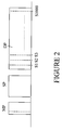
- FIG. 2 is a timing diagram showing the timing of transmissions in the downstream direction, that is from the hub to the terminals.
- the network employs two signalling phases.
- a first signalling phase termed the meta-signalling phase (MP) is used for the transmission from the network controller to each terminal on the network of a signal indicating the wavelength channel to be used by a respective terminal to receive data in the second signalling phase (SP).
- MP meta-signalling phase
- SP second signalling phase
- Each terminal is assigned a specific wavelength channel and timeslot to be used during the meta-signalling phase when the terminal is initialised. In general, this allocation of timeslot and wavelength channel for the meta-signalling phase remains fixed, being changed when the terminal is brought into or out of service.
- the wavelength channel used for the second signalling phase can be changed for each successive frame.
- each of the wavelength channels available on the network is used in the second signalling phase SB to communicate data to a sub-set of the terminals.
- the allocation of wavelength channels to terminals is carried out to make most effective use of the capacity available on the network.
- a data phase comprising 1000 time slots S1, S2....S1000 is used to communicate traffic between terminals.
- Figure 3 shows some of the key elements of figure 1 in greater detail.
- the passive wavelength-dependent routing device 3 in this example is a NxN wavelength router connected to N upsteam PONs on one side and N downstream PONs on the other side.
- An appropriate device is the StimaxTM configuration router available commercially from Instruments SA. This uses a planar diffraction grating to cross-connect signals between arrays of optical fibre waveguides.
- the wavelength router also includes a number of dummy ports each connected to a respective wavelength converter and allowing flexible re-allocation of wavelength channels through the router. The use of dummy ports is described in further detail in our above-cited international patent application W095/26592.
- the controller may comprise an appropriate computing platform, such as a UNIX workstation or a dedicated electronic processor, that controls electro-optic modulators used to modulate outgoing signalling information, and that also receives signalling input from burst mode optical receivers.
- Figure 3 shows one of the tuneable transmitters connected to a respective upstream PON and one of the tuneable receivers connected to a respective downstream PON.
- the transmitter and receiver will be co-located in a single terminal, but in some implementations, at least some terminals may have receivers only or transmitters only.
- the principle employed in the network of Figure 3 is to broadcast signalling information on each of the 800 wavelength channels, but with each channel broadcasting to only a group of terminals, rather than the entire PON.
- the terminal groupings allocated to each wavelength channel change from frame to frame.
- the signalling information to each terminal comprises up to 1,000 sets of time-slot connection data, since any terminal could be allocated up to 1,000 slots in a frame.
- each wavelength only needs to transmit 1,000 sets of slot data in total.
- Each slot may have a different source terminal for the receiver and a different destination terminal for the transmitter.
- the bits required for each slot are:
- the 50,000 terminals on a PON are first indicated, in the meta-signalling phase, which of the 800 wavelength channels to tune to in order to receive the main signalling information, ie which group of terminals they have been allocated to.
- the total downstream signalling bit-rate per channel is therefore 14.46 Mbit/s, which still represents only 2.3% of the network capacity.
- each wavelength channel transmits the main signalling information to 63 terminals (on average). But it may need to transmit to just 1 terminal, if that terminal is allocated 1,000 time-slots in a frame by the network controller, or, at the other extreme, to as many as 1,000 terminals, if each terminal has only 1 time-slot allocated to it.
- a partitioning algorithm is used to allocate groups of terminals to each wavelength channel. There are 800,000 sets of slot data to be transmitted by the 800 wavelength channels, so each wavelength can transmit 1,000 sets to its allocated group of terminals.
- the allocation algorithm is as follows. Starting with the first wavelength channel, we go through each terminal in turn using the U tX or U rX matrices, adding up the total number of time-slots allocated to them by the Network Controller.
- the U rx and U tX matrices map respectively receiving and transmitting terminals to wavelength channels and time slots for the data transmission phase. When the total exceeds 1,000, no more terminals can be allocated to that wavelength channel. The excess number above 1,000 is carried forward into the next group for the next wavelength channel. The process starts again, until the next channel's 1,000 slots have been allocated to terminals. This continues until each wavelength has been allocated its group of terminals. With this algorithm, it is possible for a given terminal to be in two groups (ie two different wavelength channels).
- each terminal can tune to each of the two wavelengths in turn (if it has only one tunable receiver).
- Signalling would in this case represent 4.6% of the network capacity.
- signalling information would only need to be transmitted once, remaining at 2.3% of network capacity.
- a lower-cost approach uses the tunable lasers in the user terminals themselves.
- a sub-set of 800 of the 50,000 terminals transmits preferably a continuous wave signal for the duration of the downstream signalling period. This ensures no additional cost for the light sources, but it requires 2.3% or 4.6% of the upstream capacity of the network to be lost to provide the unmodulated light for downstream signalling.
- the wavelength router would connect 400 different wavelengths directly into the downstream PONs, and a further 400 wavelengths into each dummy port, whence they can also be connected into the downstream PONs. These channels are then modulated with the appropriate downstream signalling information.
- a slightly less cost-effective method of generating the unmodulated wavelength channels for each downstream PON employs a single wavelength reference comb using only 800 light sources, whose power is then split 400 ways. Each of the 400 multiplexes would be coupled or switched into one of the downstream PONs.
- the reference comb could generate just 400 wavelengths per PON, while the remaining 400 are generated by the user terminals.
- Modulation of the 320,000 CW channels could be performed in two ways.
- the switchless network would already demultiplex those channels that pass through the dummy ports into separate channels at the wavelength converters. For these channels, modulation is performed by the wavelength converters 51 (preferably, to avoid additional costs), or by additional modulators.
- Those channels that are connected directly into the downstream PONs can be modulated by means of an SOA (semiconductor optical amplifier) array 52 sandwiched between a wavelength multiplexer and demultiplexer, one such system being deployed for each PON. A like system is used in the upstream PONs. This would demultiplex the channels, modulate each one in an SOA, then remultiplex them.
- SOA semiconductor optical amplifier
- wavelength channels are modulated with downstream signalling information. Even if the user terminal tunable transmitters themselves are used as light sources for downstream signalling, the network controller must still modulate 320,000 channels, ie 800 in each PON. An approach using optical delay lines may be employed to reduce the number of modulators required.
- Each downstream signalling reply packet contains 2,000 9-byte data slots. There are 200 slots to allow for each terminal receiving on two different wavelength channels in sequence. These 18 kbytes last 231.5 ⁇ s at 622 Mbit/s. A guard-band of 2.2 ⁇ s must be added to this, making 233.7 ⁇ s packet duration. The signalling must be transmitted twice, so the total duration of the downstream signalling is 467.4 ⁇ s. Given this duration, it is possible for just 40 tunable light sources and associated modulators to be used in each PON for downstream signalling, transmitting in 10ms/467.4 ⁇ s ⁇ 20 sequential slots (with frame duration of 10ms). These slots are sub-frames of the second signalling phase.
- the channels are generated by the tunable light sources in different blocks of 38 wavelength channels within each sub-frame.
- the tuneable light sources are then tuned to the next block of wavelength channels for the next sub-frame, and so on, until an entire frame has been filled.
- Optical delay lines are used, to cause the blocks of wavelength channels within the different time-slots to be delayed relative to each other so that they completely overlap each other in time by the end of a frame, i.e. so that the different sub-frames are aligned in the time domain.
- the unit of delay being 467.4 ⁇ s, the fibre delay lines need to be 93.5 km long.
- Each PON has 20 delay lines. The longest delay would be for 19 recirculations. This process is complementary to that in the upstream direction described in further detail below, where the blocks of wavelengths are spread out in time by the delay lines, rather than compressed as here.
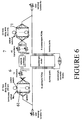
- Figure 6 shows the optical arrangements for each PON to minimise transmitters and receivers for both upstream and downstream signalling, when using 800 wavelength channels. Twelve burst-mode opto-electronic receivers 6 receive upstream optical signals via a 67-way splitter/delay network. Similarly, for the downstream PON's, 40 transmitters 7 output signals to the user terminals via a 20-way splitter/delay network.
- the average terminal bit-rate b is now the same as the operational bit-rate B, and the signalling ratio is only 0.15%.
- FTTK FTTCab or FTTExch it is possible for the terminals to signal requests to up to 1,000 different destinations in each frame with very small signalling inefficiency. This is advantageous because these terminals must handle the traffic of perhaps hundreds of customers, which will involve far more connection requests than from a single FTTH customer.
- Figure 4 shows the structure of the upstream signalling packets.
- upstream signalling is very efficient when all 800 wavelength channels are employed for signalling, we would need 800 tunable burst-mode receivers in every PON, ie 320,000 altogether, unless some more intelligent approach to receiving the signalling packets is employed. 320,000 is only a small proportion of the 20,000,000 user terminals, so the network cost would only be increased by 1.6% if a better approach were not employed.
- Figure 5 shows a possible optical arrangement for minimising the required number of tunable, burst-mode receivers for signalling in each upstream PON.
- the upstream PON fibre is split into 67 separate wavelength bands, each containing 12 different wavelength channels, by means of band-pass optical filters.
- Each band is delayed by units of 145 ⁇ s with respect to each other band, eg by the use of 29 km of optical fibre.
- each band is allowed to propagate a different integer number of times around its 29 km fibre delay line, using 2x2 optical switches.
- the delayed wavelength bands are then split 12 ways. This 12-way split allows each of 12 tunable, burst-mode receivers to select one of the resulting 12 sets of simultaneous wavelength channels.
Landscapes
- Engineering & Computer Science (AREA)
- Computer Networks & Wireless Communication (AREA)
- Optical Communication System (AREA)
- Data Exchanges In Wide-Area Networks (AREA)
Priority Applications (5)
| Application Number | Priority Date | Filing Date | Title |
|---|---|---|---|
| EP99309234A EP1102513A1 (fr) | 1999-11-19 | 1999-11-19 | Système de communication optique utilisant deux phases de signalisation |
| CA002392376A CA2392376C (fr) | 1999-11-19 | 2000-11-17 | Systeme de communication optique |
| PCT/GB2000/004392 WO2001037605A1 (fr) | 1999-11-19 | 2000-11-17 | Systeme de communication optique |
| EP00976177A EP1230823B1 (fr) | 1999-11-19 | 2000-11-17 | Systeme de communication optique |
| US10/110,993 US6798781B1 (en) | 1999-11-19 | 2000-11-17 | Optical communications system |
Applications Claiming Priority (1)
| Application Number | Priority Date | Filing Date | Title |
|---|---|---|---|
| EP99309234A EP1102513A1 (fr) | 1999-11-19 | 1999-11-19 | Système de communication optique utilisant deux phases de signalisation |
Publications (1)
| Publication Number | Publication Date |
|---|---|
| EP1102513A1 true EP1102513A1 (fr) | 2001-05-23 |
Family
ID=8241744
Family Applications (2)
| Application Number | Title | Priority Date | Filing Date |
|---|---|---|---|
| EP99309234A Withdrawn EP1102513A1 (fr) | 1999-11-19 | 1999-11-19 | Système de communication optique utilisant deux phases de signalisation |
| EP00976177A Expired - Lifetime EP1230823B1 (fr) | 1999-11-19 | 2000-11-17 | Systeme de communication optique |
Family Applications After (1)
| Application Number | Title | Priority Date | Filing Date |
|---|---|---|---|
| EP00976177A Expired - Lifetime EP1230823B1 (fr) | 1999-11-19 | 2000-11-17 | Systeme de communication optique |
Country Status (4)
| Country | Link |
|---|---|
| US (1) | US6798781B1 (fr) |
| EP (2) | EP1102513A1 (fr) |
| CA (1) | CA2392376C (fr) |
| WO (1) | WO2001037605A1 (fr) |
Families Citing this family (8)
| Publication number | Priority date | Publication date | Assignee | Title |
|---|---|---|---|---|
| US7720382B2 (en) * | 2004-04-16 | 2010-05-18 | Alcatel-Lucent Usa Inc. | Time-domain wavelength interleaved network with communications via hub node |
| US7826745B2 (en) * | 2005-12-21 | 2010-11-02 | International Business Machines Corporation | Open fiber control and loss of light propagation in time division multiplexed inter-system channel link |
| US7787765B2 (en) * | 2005-12-21 | 2010-08-31 | International Business Machines Corporation | Method and apparatus device for initializing an end-to-end link in a fiber optic communications system |
| JP4410789B2 (ja) * | 2006-12-08 | 2010-02-03 | 株式会社日立コミュニケーションテクノロジー | パッシブ光ネットワークシステム、光終端装置及び光ネットワークユニット |
| US8041217B2 (en) * | 2007-11-27 | 2011-10-18 | Fujitsu Limited | System and method for managing wavelength drift in an optical network |
| WO2011012167A1 (fr) * | 2009-07-31 | 2011-02-03 | Telefonaktiebolaget Lm Ericsson (Publ) | Appareil et procédé d'exploitation d'un réseau d'accès à multiplexage par répartition en longueur d'onde |
| CN108347326B (zh) * | 2017-01-24 | 2022-06-21 | 中兴通讯股份有限公司 | 数据的传输方法和装置 |
| WO2022044285A1 (fr) * | 2020-08-28 | 2022-03-03 | 三菱電機株式会社 | Système de communication optique, circuit de commande, support de stockage et procédé de communication optique |
Citations (2)
| Publication number | Priority date | Publication date | Assignee | Title |
|---|---|---|---|---|
| EP0614291A1 (fr) * | 1993-03-01 | 1994-09-07 | AT&T Corp. | Architecture de réseau entièrement optique |
| WO1995026592A2 (fr) * | 1994-03-29 | 1995-10-05 | British Telecommunications Public Limited Company | Reseau optique de telecommunications |
Family Cites Families (5)
| Publication number | Priority date | Publication date | Assignee | Title |
|---|---|---|---|---|
| FI96733C (fi) | 1993-06-18 | 1996-08-12 | Nokia Telecommunications Oy | Tilaajaverkkojärjestely tilaajien liittämiseksi yleiseen puhelinverkkoon |
| US5864414A (en) | 1994-01-26 | 1999-01-26 | British Telecommunications Public Limited Company | WDM network with control wavelength |
| JPH0918596A (ja) * | 1995-07-03 | 1997-01-17 | Canon Inc | 通信ネットワークおよび通信方式 |
| US6072612A (en) | 1997-08-08 | 2000-06-06 | Lucent Technologies, Inc. | WDM transmitter for optical networks using a loop-back spectrally sliced light emitting device |
| US6466343B1 (en) * | 1999-04-28 | 2002-10-15 | 3Com Corporation | System for assigning wavelengths in a wave division multiplexing based optical switch |
-
1999
- 1999-11-19 EP EP99309234A patent/EP1102513A1/fr not_active Withdrawn
-
2000
- 2000-11-17 EP EP00976177A patent/EP1230823B1/fr not_active Expired - Lifetime
- 2000-11-17 US US10/110,993 patent/US6798781B1/en not_active Expired - Fee Related
- 2000-11-17 WO PCT/GB2000/004392 patent/WO2001037605A1/fr not_active Ceased
- 2000-11-17 CA CA002392376A patent/CA2392376C/fr not_active Expired - Fee Related
Patent Citations (2)
| Publication number | Priority date | Publication date | Assignee | Title |
|---|---|---|---|---|
| EP0614291A1 (fr) * | 1993-03-01 | 1994-09-07 | AT&T Corp. | Architecture de réseau entièrement optique |
| WO1995026592A2 (fr) * | 1994-03-29 | 1995-10-05 | British Telecommunications Public Limited Company | Reseau optique de telecommunications |
Non-Patent Citations (1)
| Title |
|---|
| NEN-FU HUANG ET AL: "A MULTICAST MODEL FOR WDM-BASED LOCALLIGHTWAVE NETWORKS WITH A PASSIVE STAR TOPOLOGY", PROCEEDINGS OF THE REGION TEN CONFERENCE (TENCON),CN,BEIJING, IAP, vol. -, 1993, pages 470 - 473, XP000521464, ISBN: 0-7803-1233-3 * |
Also Published As
| Publication number | Publication date |
|---|---|
| CA2392376A1 (fr) | 2001-05-25 |
| WO2001037605A1 (fr) | 2001-05-25 |
| EP1230823A1 (fr) | 2002-08-14 |
| EP1230823B1 (fr) | 2012-03-28 |
| CA2392376C (fr) | 2007-09-18 |
| US6798781B1 (en) | 2004-09-28 |
Similar Documents
| Publication | Publication Date | Title |
|---|---|---|
| KR0168417B1 (ko) | 비동기 광 통신 시스템 | |
| An et al. | SUCCESS-HPON: A next-generation optical access architecture for smooth migration from TDM-PON to WDM-PON | |
| EP0615358B1 (fr) | Réseau optique basé sur l'interrogation à distance d'un équipement terminal | |
| Bock et al. | Hybrid WDM/TDM PON using the AWG FSR and featuring centralized light generation and dynamic bandwidth allocation | |
| EP1863204B1 (fr) | Système et procédé pour la transmission de trafic dans une pluralité de réseaux optiques passifs | |
| US6535313B1 (en) | Dynamically assignable optical signal access control apparatus | |
| KR100516152B1 (ko) | 부반송파다중화 방식이 적용된 파장 분할 다중 방식수동형 광가입자망 및 그것에서의 비대칭 패킷 데이터통신을 위한 매체접속 제어 방법 | |
| KR100237838B1 (ko) | 대용량 광비동기전송 모드스위치 | |
| US20120237217A1 (en) | Optically switched communication network | |
| US20020145775A1 (en) | TDM/WDMA passive optical network | |
| US6072612A (en) | WDM transmitter for optical networks using a loop-back spectrally sliced light emitting device | |
| Caponio et al. | Single‐Layer Optical Platform Based on WDM/TDM Multiple Access for Large‐Scale “Switchless” Networks | |
| WO2011005223A1 (fr) | Procédé et système d'affectation de longueur d'onde dans un réseau optique passif wdm/tdm | |
| US7054557B1 (en) | Technique for routing data within an optical network | |
| EP1230823B1 (fr) | Systeme de communication optique | |
| US8139939B2 (en) | Upgradeable passive optical network | |
| CA2391629C (fr) | Systeme de communication optique | |
| EP1137306A1 (fr) | Système de signalisation optique | |
| CA1287911C (fr) | Reseau de communication optique multivoie a bonds multiples | |
| US5479287A (en) | Switchable optical network with improved transmission ability | |
| Hill | Unconstrained signalling in the switchless WDMA/TDMA optical transport network | |
| Ji et al. | Spectrum variable colorless, directionless and contentionless multi-degree ROADM node | |
| Woesner | PrimeNet—A concept to apply Arrayed Waveguide Grating Multiplexers in a WDM-based fiber backbone | |
| Koonen | Optical network architectures | |
| BUTTABONI | Dynamic bandwidth and wavelength allocation strategies for long reach WDM TDM passive optical network |
Legal Events
| Date | Code | Title | Description |
|---|---|---|---|
| PUAI | Public reference made under article 153(3) epc to a published international application that has entered the european phase |
Free format text: ORIGINAL CODE: 0009012 |
|
| AK | Designated contracting states |
Kind code of ref document: A1 Designated state(s): AT BE CH CY DE DK ES FI FR GB GR IE IT LI LU MC NL PT SE |
|
| AX | Request for extension of the european patent |
Free format text: AL;LT;LV;MK;RO;SI |
|
| STAA | Information on the status of an ep patent application or granted ep patent |
Free format text: STATUS: THE APPLICATION IS DEEMED TO BE WITHDRAWN |
|
| 18D | Application deemed to be withdrawn |
Effective date: 20010320 |