EP1105931B1 - Brennstoffzellensystem - Google Patents
Brennstoffzellensystem Download PDFInfo
- Publication number
- EP1105931B1 EP1105931B1 EP99931150A EP99931150A EP1105931B1 EP 1105931 B1 EP1105931 B1 EP 1105931B1 EP 99931150 A EP99931150 A EP 99931150A EP 99931150 A EP99931150 A EP 99931150A EP 1105931 B1 EP1105931 B1 EP 1105931B1
- Authority
- EP
- European Patent Office
- Prior art keywords
- fuel cell
- gas
- cell system
- heat exchanger
- purification stage
- Prior art date
- Legal status (The legal status is an assumption and is not a legal conclusion. Google has not performed a legal analysis and makes no representation as to the accuracy of the status listed.)
- Expired - Lifetime
Links
- 239000000446 fuel Substances 0.000 title claims description 39
- 239000007789 gas Substances 0.000 claims description 79
- 239000002826 coolant Substances 0.000 claims description 19
- UGFAIRIUMAVXCW-UHFFFAOYSA-N Carbon monoxide Chemical compound [O+]#[C-] UGFAIRIUMAVXCW-UHFFFAOYSA-N 0.000 claims description 18
- 229910002091 carbon monoxide Inorganic materials 0.000 claims description 18
- QVGXLLKOCUKJST-UHFFFAOYSA-N atomic oxygen Chemical compound [O] QVGXLLKOCUKJST-UHFFFAOYSA-N 0.000 claims description 13
- 230000003647 oxidation Effects 0.000 claims description 13
- 238000007254 oxidation reaction Methods 0.000 claims description 13
- 239000001301 oxygen Substances 0.000 claims description 13
- 229910052760 oxygen Inorganic materials 0.000 claims description 13
- UFHFLCQGNIYNRP-UHFFFAOYSA-N Hydrogen Chemical compound [H][H] UFHFLCQGNIYNRP-UHFFFAOYSA-N 0.000 claims description 12
- 239000001257 hydrogen Substances 0.000 claims description 12
- 229910052739 hydrogen Inorganic materials 0.000 claims description 12
- XLYOFNOQVPJJNP-UHFFFAOYSA-N water Substances O XLYOFNOQVPJJNP-UHFFFAOYSA-N 0.000 claims description 8
- 238000000746 purification Methods 0.000 claims description 7
- 230000003197 catalytic effect Effects 0.000 claims description 5
- 239000000126 substance Substances 0.000 claims description 5
- 239000012528 membrane Substances 0.000 claims description 4
- 238000000926 separation method Methods 0.000 claims description 2
- 239000005518 polymer electrolyte Substances 0.000 claims 1
- 239000002912 waste gas Substances 0.000 claims 1
- 238000004140 cleaning Methods 0.000 description 31
- OKKJLVBELUTLKV-UHFFFAOYSA-N Methanol Chemical compound OC OKKJLVBELUTLKV-UHFFFAOYSA-N 0.000 description 18
- 239000000203 mixture Substances 0.000 description 10
- 239000003054 catalyst Substances 0.000 description 7
- 238000006243 chemical reaction Methods 0.000 description 6
- 238000001816 cooling Methods 0.000 description 6
- 238000000629 steam reforming Methods 0.000 description 4
- 239000007788 liquid Substances 0.000 description 3
- CURLTUGMZLYLDI-UHFFFAOYSA-N Carbon dioxide Chemical compound O=C=O CURLTUGMZLYLDI-UHFFFAOYSA-N 0.000 description 2
- 238000010276 construction Methods 0.000 description 2
- 230000008878 coupling Effects 0.000 description 2
- 238000010168 coupling process Methods 0.000 description 2
- 238000005859 coupling reaction Methods 0.000 description 2
- 238000004519 manufacturing process Methods 0.000 description 2
- BASFCYQUMIYNBI-UHFFFAOYSA-N platinum Chemical compound [Pt] BASFCYQUMIYNBI-UHFFFAOYSA-N 0.000 description 2
- KJTLSVCANCCWHF-UHFFFAOYSA-N Ruthenium Chemical compound [Ru] KJTLSVCANCCWHF-UHFFFAOYSA-N 0.000 description 1
- 229910021536 Zeolite Inorganic materials 0.000 description 1
- 238000009835 boiling Methods 0.000 description 1
- 239000006227 byproduct Substances 0.000 description 1
- 229910002092 carbon dioxide Inorganic materials 0.000 description 1
- 239000001569 carbon dioxide Substances 0.000 description 1
- 239000011248 coating agent Substances 0.000 description 1
- 238000000576 coating method Methods 0.000 description 1
- 230000001419 dependent effect Effects 0.000 description 1
- HNPSIPDUKPIQMN-UHFFFAOYSA-N dioxosilane;oxo(oxoalumanyloxy)alumane Chemical compound O=[Si]=O.O=[Al]O[Al]=O HNPSIPDUKPIQMN-UHFFFAOYSA-N 0.000 description 1
- 238000009826 distribution Methods 0.000 description 1
- 238000003487 electrochemical reaction Methods 0.000 description 1
- 238000009434 installation Methods 0.000 description 1
- 239000000463 material Substances 0.000 description 1
- 238000000034 method Methods 0.000 description 1
- TWNQGVIAIRXVLR-UHFFFAOYSA-N oxo(oxoalumanyloxy)alumane Chemical compound O=[Al]O[Al]=O TWNQGVIAIRXVLR-UHFFFAOYSA-N 0.000 description 1
- 229910052697 platinum Inorganic materials 0.000 description 1
- 230000008569 process Effects 0.000 description 1
- 239000000047 product Substances 0.000 description 1
- 230000009467 reduction Effects 0.000 description 1
- 229910052707 ruthenium Inorganic materials 0.000 description 1
- 239000010457 zeolite Substances 0.000 description 1
Images

Classifications
-
- C—CHEMISTRY; METALLURGY
- C10—PETROLEUM, GAS OR COKE INDUSTRIES; TECHNICAL GASES CONTAINING CARBON MONOXIDE; FUELS; LUBRICANTS; PEAT
- C10K—PURIFYING OR MODIFYING THE CHEMICAL COMPOSITION OF COMBUSTIBLE GASES CONTAINING CARBON MONOXIDE
- C10K3/00—Modifying the chemical composition of combustible gases containing carbon monoxide to produce an improved fuel, e.g. one of different calorific value, which may be free from carbon monoxide
- C10K3/02—Modifying the chemical composition of combustible gases containing carbon monoxide to produce an improved fuel, e.g. one of different calorific value, which may be free from carbon monoxide by catalytic treatment
- C10K3/04—Modifying the chemical composition of combustible gases containing carbon monoxide to produce an improved fuel, e.g. one of different calorific value, which may be free from carbon monoxide by catalytic treatment reducing the carbon monoxide content, e.g. water-gas shift [WGS]
-
- H—ELECTRICITY
- H01—ELECTRIC ELEMENTS
- H01M—PROCESSES OR MEANS, e.g. BATTERIES, FOR THE DIRECT CONVERSION OF CHEMICAL ENERGY INTO ELECTRICAL ENERGY
- H01M8/00—Fuel cells; Manufacture thereof
- H01M8/04—Auxiliary arrangements, e.g. for control of pressure or for circulation of fluids
- H01M8/04007—Auxiliary arrangements, e.g. for control of pressure or for circulation of fluids related to heat exchange
-
- H—ELECTRICITY
- H01—ELECTRIC ELEMENTS
- H01M—PROCESSES OR MEANS, e.g. BATTERIES, FOR THE DIRECT CONVERSION OF CHEMICAL ENERGY INTO ELECTRICAL ENERGY
- H01M8/00—Fuel cells; Manufacture thereof
- H01M8/06—Combination of fuel cells with means for production of reactants or for treatment of residues
- H01M8/0662—Treatment of gaseous reactants or gaseous residues, e.g. cleaning
-
- Y—GENERAL TAGGING OF NEW TECHNOLOGICAL DEVELOPMENTS; GENERAL TAGGING OF CROSS-SECTIONAL TECHNOLOGIES SPANNING OVER SEVERAL SECTIONS OF THE IPC; TECHNICAL SUBJECTS COVERED BY FORMER USPC CROSS-REFERENCE ART COLLECTIONS [XRACs] AND DIGESTS
- Y02—TECHNOLOGIES OR APPLICATIONS FOR MITIGATION OR ADAPTATION AGAINST CLIMATE CHANGE
- Y02E—REDUCTION OF GREENHOUSE GAS [GHG] EMISSIONS, RELATED TO ENERGY GENERATION, TRANSMISSION OR DISTRIBUTION
- Y02E60/00—Enabling technologies; Technologies with a potential or indirect contribution to GHG emissions mitigation
- Y02E60/30—Hydrogen technology
- Y02E60/50—Fuel cells
Definitions
- the invention relates to a fuel cell system according to the Preamble of claim 1.
- a fuel cell system is known from EP 0 743 694 A1 known, with the help of a reformer from a Methanol / water mixture a hydrogen-rich, Gas containing carbon monoxide is generated. Subsequently the carbon monoxide is in a gas cleaning stage Adding oxygen using selective oxidation removed from the reformate.
- a heat exchanger is provided by Water or oil is flowing through. To cool the Cooling medium is another liquid / air heat exchanger intended.
- US 52 71 916 A1 is a two-stage device for the selective oxidation of carbon monoxide in known a hydrogen-rich gas mixture.
- This Gas cleaning stage also has a heat exchanger preferably from a liquid cooling medium with a Boiling point between 160 ° and 175 ° C is flowed through.
- a heat exchanger preferably from a liquid cooling medium with a Boiling point between 160 ° and 175 ° C is flowed through.
- the gas mixture In front entry into a downstream fuel cell the gas mixture in another flowed through by water Heat exchanger to the required Cooled fuel cell temperature.
- WO 93/19005 A1 generic fuel cell system known. at this device is in a hydrogen rich Carbon monoxide contained in a gas mixture in a two-stage Gas cleaning stage with the addition of oxygen selectively oxidized. In both gas cleaning stages there are one Liquid-flow heat exchanger provided. In addition, there is another between the two stages Heat exchanger provided.
- the gas cleaning stage as a gas-gas heat exchanger and the use of the anode and / or Cathode exhaust from the fuel cell as Cooling medium, a simplified device is created, since no additional coolant circuit with associated Liquid / air heat exchanger is required. Thereby the required installation space and the cost of the Contraption.
- the enthalpy flow is on the cooling side, ie in the Anode and / or cathode exhaust, depending on the load, so that accordingly the heat of reaction that arises at selective oxidation with large load more, with small load less energy is dissipated. It also improves the overall efficiency of the system, if the anode or Downstream cathode exhaust Catalytic burner is fed because of the anode or Cathode exhaust gas when flowing through the Heat exchanger is preheated. This energy must then subsequently no longer supplied in the catalytic burner become. Overall, the entire system goes through cooling no thermal energy is lost in the gas cleaning stage.
- Fuel cell system among other things Reformate cooler between gas cleaning stage and Fuel cell and / or between gas generating device and gas cleaning stage can be dispensed with, since the cooling medium essentially the operating temperature of the fuel cell having. This allows multiple functions in one Component united, whereby on the one hand less access and Derivatives are needed and on the other hand weight and Space savings and the associated Cost reduction can be realized.
- the fuel cell system according to FIG. 1 contains a gas generating device 1, a gas cleaning stage 2 and one total designated 3 fuel cell.
- the Fuel cell 3 contains an anode compartment 5 and one Cathode compartment 6 through a proton-conducting membrane 7 are separated from each other.
- In the anode compartment 5 is a hydrogen-rich gas, 6 oxygen in the cathode compartment or air supplied.
- the membrane 7 is on provide a suitable catalyst on both sides. This oxidizes the hydrogen in the anode, whereby the remaining proton through the membrane to the cathode can hike. There the oxygen is reduced and combines with the proton to form water vapor. At this electrochemical reaction creates a voltage that can be supplied to an external load.
- the gas generating device 1 becomes a fuel made a hydrogen-rich gas.
- This is what it is about preferably a device for Steam reforming and / or for partial oxidation.
- methanol, gasoline or other hydrocarbonaceous substances used become.
- the embodiment based on the Steam reforming of methanol is described the scope of protection is not limited to this application his.
- the carbon monoxide contained in the gas mixture is for the Fuel cell 3 harmful. For this reason between the gas generating device 1 and the Fuel cell 3 arranged the gas cleaning stage 2. Through the gas cleaning stage 2, the carbon monoxide content reduced to ⁇ 50 ppm in the gas mixture. It will Carbon monoxide on a suitable catalyst, for example platinum and / or ruthenium on a support made of zeolite or aluminum oxide, with the addition of oxygen selectively oxidized. The oxygen can, as in Embodiment shown, in a suitable amount the gas cleaning stage 2 added to the gas mixture become. However, it is also possible to add oxygen to one or several positions directly in gas cleaning stage 2 supply.
- a suitable catalyst for example platinum and / or ruthenium on a support made of zeolite or aluminum oxide
- the maximum permissible CO input concentration for the gas cleaning stage 2 is severely limited by that resulting adiabatic temperature increase. Because the lambda, not the ratio of oxygen to carbon monoxide may be too small, in addition to carbon monoxide a certain proportion of hydrogen is also oxidized. The one there released energy also contributes to adiabatic Temperature increase at. Will not be gas cleaning level 2 actively cooled, the temperature rises quickly and the Process runs at too high a temperature level. This has the consequence that with increasing CO input concentration more hydrogen and less carbon monoxide is oxidized. The temperature must therefore be in a predetermined range move. The heat of reaction is partially removed Temperature maximum reduced, so that an oxidation of higher CO input concentrations is possible. Through the Temperature control, sales and selectivity are increased, while CO build-up occurs by approaching the water-gas shift equilibrium is reduced.
- the anode and / or cathode exhaust gas or partial streams thereof are used.
- the Gas cleaning stage 2 for example from the anode exhaust gas flows through.
- the use of the anode and / or cathode exhaust gas as cooling medium has a great many Advantages on. For one, it doesn't need anything else Cooling system or an additional cooling medium be provided, whereby the overall system is essential simplified. Gas-gas heat exchangers are available Components that do not require complex construction make and therefore inexpensive to manufacture are realized. Of course, according to the invention but also more complex gas-gas heat exchangers be used. On the one hand, it naturally prevents poorer heat transfer in gas-gas heat exchangers too strong coupling of the reaction to the cooling medium. This can prevent the reaction from being too strong is cooled and there is no longer any oxidation can, since the degree of coverage of the catalyst with Carbon monoxide gets too high.
- the enthalpy flow is also on the cooling side of the gas-gas heat exchanger load-dependent, so that completely accordingly the resulting heat of reaction during CO oxidation high heat more, less heat dissipated at low load becomes.
- the total efficiency of the system can be increased because this energy at a usually complete downstream catalytic Oxidation of the anode and / or cathode exhaust no longer must be generated.
- the gas cleaning stage 2 and the fuel cell 3 can optionally have a drainage unit 11 for separation of condensing water.
- Farther can have a bypass line 12 parallel to the heat exchanger 4 Associated bypass valve 13 can be provided. This can the bypass valve 13 at any point in the Bypass line 12 are arranged.
- To control the Bypass valve 13 is also a control unit 10 intended. The desired can be in the control unit Bypass volume flow based on specified map values and / or depending on the temperature in the cooling medium and / or determined in reformate and using a Control of the bypass valve 13 set become.
- the temperature of the cooling medium or Reformate gas flow is at a suitable point in the Gas cleaning stage 2, the heat exchanger 4 and / or the associated feed and discharge lines measured and made available to the control unit.
- the heat exchanger is preferably a Plate arrangement realized, the cooling medium and the Reformatgasstrom preferably be performed in countercurrent. That for the selective oxidation in the gas cleaning stage 2 necessary catalyst material is preferably as Coating on a heat exchanging surface in the Heat exchanger 4 applied, the heat exchanging All or part of the surface coated with catalyst can be.
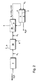
- Fig. 2 shows a further embodiment, wherein 1 identical parts with the same reference numerals Marked are. Notwithstanding Fig. 1, the 2 a first stage 2a and a second stage 2b. However, it is also possible to provide further stages.
- To cool the first Gas purification stage 2a can be done by any Cooling medium, such as a heat transfer oil, the corresponding feed and discharge lines 8, 9 respectively is discharged, flowed through.
- the oxygen can, as in the exemplary embodiment shown, each in a suitable amount before each Stage 2a, 2b are added to the gas mixture. It is however, it is also possible to add oxygen to one or more Place directly in the gas cleaning stages 2a, 2b supply. In contrast to Fig. 1 there is also none Bypass line and also no drainage device intended. However, it is of course possible that Features from the two exemplary embodiments arbitrarily combine. In addition to the arrangement shown with oil-cooled first gas cleaning stage 2a and gas-cooled second Gas cleaning level 2b, it is also possible to all Gas cleaning stages 2a, 2b with fuel cell exhaust gas cool. It is crucial, however, that the last stage of the Gas cleaning stage 2b directly with the fuel cell exhaust gas is cooled around the reformate before entering the fuel cell 3 towards the appropriate operating temperature bring.
Landscapes
- Chemical & Material Sciences (AREA)
- Engineering & Computer Science (AREA)
- General Chemical & Material Sciences (AREA)
- Chemical Kinetics & Catalysis (AREA)
- Sustainable Development (AREA)
- Life Sciences & Earth Sciences (AREA)
- Manufacturing & Machinery (AREA)
- Combustion & Propulsion (AREA)
- Sustainable Energy (AREA)
- Electrochemistry (AREA)
- Oil, Petroleum & Natural Gas (AREA)
- Organic Chemistry (AREA)
- Fuel Cell (AREA)
- Hydrogen, Water And Hydrids (AREA)
- Industrial Gases (AREA)
Description
- Fig. 1
- die den prinzipiellen Aufbau eines erfindungsgemäßen Brennstoffzellensystems mit einem Wärmetauscher mit Bypassleitung und
- Fig. 2
- ein weiteres Ausführungsbeispiel mit einer mehrstufigen Gasreinigungsstufe und einem Wärmetauscher ohne Bypassleitung zeigt.
Claims (7)
- Brennstoffzellensystem mitdadurch gekennzeichnet, daß im gasgekühlten Wärmetauscher (4) als Kühlmedium das aus der Brennstoffzelle (3) austretende Anoden- und/oder Kathodenabgas verwendet wird.einer Brennstoffzelle, die einen Kathoden raum, einen Anodenraum und eine dazwischenliegende Polymerelektrolytmembran aufweist, wobei dem Kathodenraum ein sauerstoffhaltiges Gas und dem Anodenraum ein wasserstoffhaltiges Gas zugeführt wird,einer Gaserzeugungsvorrichtung, in der aus einem Brennstoff mit Hilfe der Wasserdampfreformierung und/oder partiellen Oxidation ein wasserstoffreiches, Kohlenmonoxid enthaltendes Reformat hergestellt wird,einer Gasreinigungsstufe, in der das Kohlenmonoxid im Reformat unter Zugabe von Sauerstoff an einem geeigneten Katalysator selektiv oxidiert wird, undeinem in der Gasreinigungsstufe angeordneten und von einem Kühlmedium durchströmten Wärmetauscher zur Abfuhr thermischer Energie,
- Brennstoffzellensystem nach Anspruch 1,
dadurch gekennzeichnet, daß die Gasreinigungsstufe (2) mehrstufig ausgeführt ist und daß der gasgekühlte Wärmetauscher (4) zumindest der letzten Gasreinigungsstufe (2b) zugeordnet ist. - Brennstoffzellensystem nach Anspruch 1,
dadurch gekennzeichnet, daß parallel zum Wärmetauscher (4) eine Bypassleitung (12) für das Kühlmedium und ein zugehöriges Bypassventil (13) angeordnet ist. - Brennstoffzellensystem nach Anspruch 4,
dadurch gekennzeichnet, daß ein Steuergerät (10) für die Ansteuerung des Bypassventils (13) anhand vorgegebener Kennfeldwerte und/oder in Abhängigkeit von einer Temperatur im Kühlmittel und/oder im Reformat vorgesehen ist. - Brennstoffzellensystem nach Anspruch 1,
dadurch gekennzeichnet, daß eine wärmeaustauschende Fläche in der Gasreinigungsstufe (2) zumindest teilweise mit dem Katalysator zur selektiven Oxidation des Kohlenmonoxids beschichtet ist. - Brennstoffzellensystem nach Anspruch 1,
dadurch gekennzeichnet, daß das Reformat und das Kühlmedium im Wärmetauscher (4) im Gegenstrom geführt sind. - Brennstoffzellensystem nach Anspruch 1,
dadurch gekennzeichnet, daß stromab der Gasreinigungsstufe (2) eine Entwässerungseinheit (11) zur Abscheidung kondensierenden Wassers angeordnet ist.
Applications Claiming Priority (3)
| Application Number | Priority Date | Filing Date | Title |
|---|---|---|---|
| DE19832389 | 1998-07-18 | ||
| DE19832389A DE19832389C2 (de) | 1998-07-18 | 1998-07-18 | Brennstoffzellensystem |
| PCT/EP1999/004353 WO2000004600A1 (de) | 1998-07-18 | 1999-06-23 | Brennstoffzellensystem |
Publications (2)
| Publication Number | Publication Date |
|---|---|
| EP1105931A1 EP1105931A1 (de) | 2001-06-13 |
| EP1105931B1 true EP1105931B1 (de) | 2002-04-24 |
Family
ID=7874548
Family Applications (1)
| Application Number | Title | Priority Date | Filing Date |
|---|---|---|---|
| EP99931150A Expired - Lifetime EP1105931B1 (de) | 1998-07-18 | 1999-06-23 | Brennstoffzellensystem |
Country Status (5)
| Country | Link |
|---|---|
| US (1) | US6620536B1 (de) |
| EP (1) | EP1105931B1 (de) |
| JP (1) | JP3667231B2 (de) |
| DE (2) | DE19832389C2 (de) |
| WO (1) | WO2000004600A1 (de) |
Families Citing this family (26)
| Publication number | Priority date | Publication date | Assignee | Title |
|---|---|---|---|---|
| US7195663B2 (en) | 1996-10-30 | 2007-03-27 | Idatech, Llc | Hydrogen purification membranes, components and fuel processing systems containing the same |
| US6537352B2 (en) | 1996-10-30 | 2003-03-25 | Idatech, Llc | Hydrogen purification membranes, components and fuel processing systems containing the same |
| US6376113B1 (en) | 1998-11-12 | 2002-04-23 | Idatech, Llc | Integrated fuel cell system |
| DE19931064C2 (de) * | 1999-07-01 | 2003-08-14 | P21 Power For The 21St Century | Anordnung und Verfahren zum Erzeugen und/oder Aufbereiten eines Brennstoffs, insbesondere eines Brennstoffs für eine Brennstoffzelle und deren Verwendung |
| AU6378400A (en) | 1999-07-27 | 2001-02-13 | Idatech, Llc | Fuel cell system controller |
| US6979507B2 (en) | 2000-07-26 | 2005-12-27 | Idatech, Llc | Fuel cell system controller |
| US6451464B1 (en) | 2000-01-03 | 2002-09-17 | Idatech, Llc | System and method for early detection of contaminants in a fuel processing system |
| US6465118B1 (en) | 2000-01-03 | 2002-10-15 | Idatech, Llc | System and method for recovering thermal energy from a fuel processing system |
| DE10013687B4 (de) | 2000-03-21 | 2007-06-28 | Nucellsys Gmbh | Brennstoffzellensystem und Verfahren zum Betreiben desselben |
| DE10037825A1 (de) * | 2000-08-03 | 2002-05-16 | Xcellsis Gmbh | Brennstoffzellensystem |
| DE10041384C1 (de) * | 2000-08-23 | 2002-04-04 | Xcellsis Gmbh | Verfahren und Vorrichtung zum Erzeugen eines wasserstoffreichen Gases |
| DE10053597A1 (de) * | 2000-10-28 | 2002-08-08 | Xcellsis Gmbh | Gaserzeugungssystem für ein Brennstoffzellensystem und Verfahren zur Bereitstellung wasserstoffhaltigen Brennstoffs |
| DE10136970C2 (de) * | 2001-07-28 | 2003-11-27 | Ballard Power Systems | Vorrichtung zur Erzeugung von wasserstoffhaltigem Gas für eine Brennstoffzellenanlage |
| DE10137592B4 (de) * | 2001-08-01 | 2007-06-14 | Nucellsys Gmbh | Gaserzeugungssystem in einer Brennstoffzellenanlage sowie seine Verwendung in einem Kraftfahrzeug |
| DE10212872A1 (de) * | 2002-03-22 | 2003-10-02 | Volkswagen Ag | Verfahren zum einstellbaren Kühlen eines Betriebsmediumstroms in einem Wärmetauscher, entsprechender Wärmetauscher und entsprechendes Brennstoffzellensystem |
| DE10213937A1 (de) * | 2002-03-28 | 2003-10-23 | Daimler Chrysler Ag | Vorrichtung zur selektiven katalytischen Oxidation von CO |
| US6821663B2 (en) * | 2002-10-23 | 2004-11-23 | Ion America Corporation | Solid oxide regenerative fuel cell |
| AT413008B (de) * | 2004-02-12 | 2005-09-26 | Avl List Gmbh | Vorrichtung und verfahren zur kühlung heisser prozessgase |
| US7842428B2 (en) | 2004-05-28 | 2010-11-30 | Idatech, Llc | Consumption-based fuel cell monitoring and control |
| US7601302B2 (en) | 2005-09-16 | 2009-10-13 | Idatech, Llc | Self-regulating feedstock delivery systems and hydrogen-generating fuel processing assemblies and fuel cell systems incorporating the same |
| US7659019B2 (en) | 2005-09-16 | 2010-02-09 | Idatech, Llc | Thermally primed hydrogen-producing fuel cell system |
| US10476093B2 (en) | 2016-04-15 | 2019-11-12 | Chung-Hsin Electric & Machinery Mfg. Corp. | Membrane modules for hydrogen separation and fuel processors and fuel cell systems including the same |
| CN109742426B (zh) * | 2019-01-07 | 2020-10-02 | 中氢新能技术有限公司 | 一种甲醇燃料电池的排气阀角度的控制系统及其控制方法 |
| DE102019207997A1 (de) * | 2019-05-31 | 2020-12-03 | Siemens Mobility GmbH | Brennstoffzellenanordnung und Schienenfahrzeug mit einer Brennstoffzellenanordnung |
| US11316180B2 (en) | 2020-05-21 | 2022-04-26 | H2 Powertech, Llc | Hydrogen-producing fuel cell systems and methods of operating hydrogen-producing fuel cell systems for backup power operations |
| US11712655B2 (en) | 2020-11-30 | 2023-08-01 | H2 Powertech, Llc | Membrane-based hydrogen purifiers |
Family Cites Families (13)
| Publication number | Priority date | Publication date | Assignee | Title |
|---|---|---|---|---|
| US5271916A (en) * | 1991-07-08 | 1993-12-21 | General Motors Corporation | Device for staged carbon monoxide oxidation |
| WO1993019005A1 (en) * | 1992-03-19 | 1993-09-30 | International Fuel Cells Corporation | Method of and apparatus for removing carbon monoxide from gaseous media |
| JPH08106913A (ja) | 1994-09-30 | 1996-04-23 | Aisin Aw Co Ltd | 燃料電池発電装置 |
| DE4438555C1 (de) * | 1994-10-28 | 1996-03-07 | Mtu Friedrichshafen Gmbh | Brennstoffzellenanordnung mit Reformierungseinrichtung |
| JPH0930802A (ja) * | 1995-05-15 | 1997-02-04 | Toyota Motor Corp | 一酸化炭素濃度低減装置及びメタノール濃度低減装置並びに燃料改質装置 |
| US5853674A (en) * | 1996-01-11 | 1998-12-29 | International Fuel Cells, Llc | Compact selective oxidizer assemblage for fuel cell power plant |
| JP3870455B2 (ja) * | 1996-09-27 | 2007-01-17 | トヨタ自動車株式会社 | 一酸化炭素濃度低減装置およびその方法並びに燃料電池発電装置 |
| JP4015225B2 (ja) * | 1997-04-30 | 2007-11-28 | 三菱重工業株式会社 | 一酸化炭素除去装置 |
| TW353206B (en) * | 1997-05-17 | 1999-02-21 | United Microelectronics Corp | Process for producing self-aligned salicide having high temperature stability |
| DE19727589B4 (de) * | 1997-06-28 | 2004-07-08 | Ballard Power Systems Ag | Vorrichtung und Verfahren zum Starten der Vorrichtung zur Erzeugung von wasserstoffreichem Gas |
| GB9720353D0 (en) * | 1997-09-25 | 1997-11-26 | Johnson Matthey Plc | Hydrogen purification |
| DE19847211C1 (de) * | 1998-10-13 | 2000-05-18 | Dbb Fuel Cell Engines Gmbh | Verfahren zum Betreiben einer Reformer/CO-Oxidationseinheit |
| US6254214B1 (en) * | 1999-06-11 | 2001-07-03 | Lexmark International, Inc. | System for cooling and maintaining an inkjet print head at a constant temperature |
-
1998
- 1998-07-18 DE DE19832389A patent/DE19832389C2/de not_active Expired - Fee Related
-
1999
- 1999-06-23 EP EP99931150A patent/EP1105931B1/de not_active Expired - Lifetime
- 1999-06-23 US US09/743,984 patent/US6620536B1/en not_active Expired - Fee Related
- 1999-06-23 JP JP2000560627A patent/JP3667231B2/ja not_active Expired - Fee Related
- 1999-06-23 DE DE59901314T patent/DE59901314D1/de not_active Expired - Fee Related
- 1999-06-23 WO PCT/EP1999/004353 patent/WO2000004600A1/de not_active Ceased
Also Published As
| Publication number | Publication date |
|---|---|
| EP1105931A1 (de) | 2001-06-13 |
| JP3667231B2 (ja) | 2005-07-06 |
| JP2002520802A (ja) | 2002-07-09 |
| DE59901314D1 (de) | 2002-05-29 |
| DE19832389A1 (de) | 2000-01-27 |
| US6620536B1 (en) | 2003-09-16 |
| WO2000004600A1 (de) | 2000-01-27 |
| DE19832389C2 (de) | 2003-04-24 |
Similar Documents
| Publication | Publication Date | Title |
|---|---|---|
| EP1105931B1 (de) | Brennstoffzellensystem | |
| EP0911897B1 (de) | Anlage zur Wasserdampfreformierung eines Kohlenwasserstoffs,insbesondere von Methanol, und zur Kohlenmonoxid-Reduktion, und Betriebsverfahren hierfür | |
| DE2927655C2 (de) | Verfahren zum Betreiben einer elektrochemischen Brennstoffzelle und dafür geeignete Brennstoffzelle | |
| EP0921584B1 (de) | Anlage zur Wasserdampfreformierung eines Kohlenwasserstoffs | |
| EP0790657B1 (de) | Verfahren zum Betreiben eines Brennstoffzellensystems | |
| EP0859421B1 (de) | Flüssigbrennstoffzellensystem | |
| DE10120021A1 (de) | Brennstoffzellensystem mit einem thermisch integrierten, isothermischen Co-Reinigungsteilsystem | |
| EP0974393B1 (de) | Reformierungsreaktor mit katalytischer Brennereinheit | |
| WO2004013924A2 (de) | Verbundbrennstoffzellenanlage | |
| DE19753720C2 (de) | Vorrichtung zur selektiven katalytischen Oxidation von Kohlenmonoxid | |
| AT523488A1 (de) | Schutz-Reformervorrichtung zum Schutz eines Anodenabschnitts eines Brennstoffzellenstapels | |
| EP0814054A2 (de) | Reformierungsreaktor, insbesondere zur Wasserdampfreformierung von Methanol | |
| EP1178552B1 (de) | Brennstoffzellensystem | |
| DE102004010014A1 (de) | Reformer und Verfahren zum Umsetzen von Brennstoff und Oxidationsmittel zu Reformat | |
| EP2200114B1 (de) | Reformer-Brennstoffzellen-System | |
| DE19958404C2 (de) | Vorrichtung zur selektiven katalytischen Oxidation von Kohlenmonoxid | |
| EP1370350A1 (de) | Reaktor mit gleichmässiger verteilung von betriebsmitteln | |
| DE202022104076U1 (de) | Brennstoffzellensysteme | |
| EP1919019B1 (de) | Brennstoffzellensystem mit Brenneranordnung | |
| DE10025667B4 (de) | Verfahren zum Betreiben einer Gaserzeugungsvorrichtung in einem Brennstoffzellensystem | |
| DE10137592B4 (de) | Gaserzeugungssystem in einer Brennstoffzellenanlage sowie seine Verwendung in einem Kraftfahrzeug | |
| EP0873782A1 (de) | Reformierungsreaktoranlage, insbesondere zur Wasserdampfreformierung von Methanol | |
| EP0867962A1 (de) | Zweistufiger Reformierungsreaktor zur Wasserdampfreformierung von Methanol | |
| DE10149658B4 (de) | Vorrichtung und Verfahren zur katalytischen Brenngasaufbereitung eines wasserstoffreichen Reformergases für eine Brennstoffzelle | |
| DE10111259A1 (de) | Vorrichtung zur Erzeugung eines wasserstoffhaltigen Gases aus einem Kohlenwasserstoff |
Legal Events
| Date | Code | Title | Description |
|---|---|---|---|
| PUAI | Public reference made under article 153(3) epc to a published international application that has entered the european phase |
Free format text: ORIGINAL CODE: 0009012 |
|
| 17P | Request for examination filed |
Effective date: 20001201 |
|
| AK | Designated contracting states |
Kind code of ref document: A1 Designated state(s): DE FR GB IT |
|
| GRAG | Despatch of communication of intention to grant |
Free format text: ORIGINAL CODE: EPIDOS AGRA |
|
| 17Q | First examination report despatched |
Effective date: 20010717 |
|
| GRAG | Despatch of communication of intention to grant |
Free format text: ORIGINAL CODE: EPIDOS AGRA |
|
| GRAH | Despatch of communication of intention to grant a patent |
Free format text: ORIGINAL CODE: EPIDOS IGRA |
|
| REG | Reference to a national code |
Ref country code: GB Ref legal event code: IF02 |
|
| GRAH | Despatch of communication of intention to grant a patent |
Free format text: ORIGINAL CODE: EPIDOS IGRA |
|
| GRAA | (expected) grant |
Free format text: ORIGINAL CODE: 0009210 |
|
| AK | Designated contracting states |
Kind code of ref document: B1 Designated state(s): DE FR GB IT |
|
| REG | Reference to a national code |
Ref country code: GB Ref legal event code: FG4D Free format text: NOT ENGLISH |
|
| REF | Corresponds to: |
Ref document number: 59901314 Country of ref document: DE Date of ref document: 20020529 |
|
| GBT | Gb: translation of ep patent filed (gb section 77(6)(a)/1977) |
Effective date: 20020718 |
|
| ET | Fr: translation filed | ||
| PLBE | No opposition filed within time limit |
Free format text: ORIGINAL CODE: 0009261 |
|
| STAA | Information on the status of an ep patent application or granted ep patent |
Free format text: STATUS: NO OPPOSITION FILED WITHIN TIME LIMIT |
|
| 26N | No opposition filed |
Effective date: 20030127 |
|
| REG | Reference to a national code |
Ref country code: FR Ref legal event code: CD |
|
| REG | Reference to a national code |
Ref country code: FR Ref legal event code: TP Ref country code: FR Ref legal event code: CD |
|
| PGFP | Annual fee paid to national office [announced via postgrant information from national office to epo] |
Ref country code: IT Payment date: 20090624 Year of fee payment: 11 Ref country code: FR Payment date: 20090615 Year of fee payment: 11 |
|
| PGFP | Annual fee paid to national office [announced via postgrant information from national office to epo] |
Ref country code: GB Payment date: 20090618 Year of fee payment: 11 Ref country code: DE Payment date: 20090622 Year of fee payment: 11 |
|
| GBPC | Gb: european patent ceased through non-payment of renewal fee |
Effective date: 20100623 |
|
| REG | Reference to a national code |
Ref country code: FR Ref legal event code: ST Effective date: 20110228 |
|
| PG25 | Lapsed in a contracting state [announced via postgrant information from national office to epo] |
Ref country code: IT Free format text: LAPSE BECAUSE OF NON-PAYMENT OF DUE FEES Effective date: 20100623 |
|
| PG25 | Lapsed in a contracting state [announced via postgrant information from national office to epo] |
Ref country code: DE Free format text: LAPSE BECAUSE OF NON-PAYMENT OF DUE FEES Effective date: 20110101 |
|
| PG25 | Lapsed in a contracting state [announced via postgrant information from national office to epo] |
Ref country code: FR Free format text: LAPSE BECAUSE OF NON-PAYMENT OF DUE FEES Effective date: 20100630 |
|
| PG25 | Lapsed in a contracting state [announced via postgrant information from national office to epo] |
Ref country code: GB Free format text: LAPSE BECAUSE OF NON-PAYMENT OF DUE FEES Effective date: 20100623 |