EP1106243A2 - Dynamischer Mischer. - Google Patents
Dynamischer Mischer. Download PDFInfo
- Publication number
- EP1106243A2 EP1106243A2 EP00810432A EP00810432A EP1106243A2 EP 1106243 A2 EP1106243 A2 EP 1106243A2 EP 00810432 A EP00810432 A EP 00810432A EP 00810432 A EP00810432 A EP 00810432A EP 1106243 A2 EP1106243 A2 EP 1106243A2
- Authority
- EP
- European Patent Office
- Prior art keywords
- rotor
- mixing
- dynamic mixer
- components
- mixer according
- Prior art date
- Legal status (The legal status is an assumption and is not a legal conclusion. Google has not performed a legal analysis and makes no representation as to the accuracy of the status listed.)
- Granted
Links
- 238000007789 sealing Methods 0.000 claims description 5
- 210000001520 comb Anatomy 0.000 claims description 2
- 239000000969 carrier Substances 0.000 description 1
- 230000002093 peripheral effect Effects 0.000 description 1
Images


Classifications
-
- B—PERFORMING OPERATIONS; TRANSPORTING
- B05—SPRAYING OR ATOMISING IN GENERAL; APPLYING FLUENT MATERIALS TO SURFACES, IN GENERAL
- B05C—APPARATUS FOR APPLYING FLUENT MATERIALS TO SURFACES, IN GENERAL
- B05C17/00—Hand tools or apparatus using hand held tools, for applying liquids or other fluent materials to, for spreading applied liquids or other fluent materials on, or for partially removing applied liquids or other fluent materials from, surfaces
- B05C17/005—Hand tools or apparatus using hand held tools, for applying liquids or other fluent materials to, for spreading applied liquids or other fluent materials on, or for partially removing applied liquids or other fluent materials from, surfaces for discharging material from a reservoir or container located in or on the hand tool through an outlet orifice by pressure without using surface contacting members like pads or brushes
- B05C17/00553—Hand tools or apparatus using hand held tools, for applying liquids or other fluent materials to, for spreading applied liquids or other fluent materials on, or for partially removing applied liquids or other fluent materials from, surfaces for discharging material from a reservoir or container located in or on the hand tool through an outlet orifice by pressure without using surface contacting members like pads or brushes with means allowing the stock of material to consist of at least two different components
- B05C17/00566—Hand tools or apparatus using hand held tools, for applying liquids or other fluent materials to, for spreading applied liquids or other fluent materials on, or for partially removing applied liquids or other fluent materials from, surfaces for discharging material from a reservoir or container located in or on the hand tool through an outlet orifice by pressure without using surface contacting members like pads or brushes with means allowing the stock of material to consist of at least two different components with a dynamic mixer in the nozzle
-
- A—HUMAN NECESSITIES
- A61—MEDICAL OR VETERINARY SCIENCE; HYGIENE
- A61C—DENTISTRY; APPARATUS OR METHODS FOR ORAL OR DENTAL HYGIENE
- A61C5/00—Filling or capping teeth
- A61C5/60—Devices specially adapted for pressing or mixing capping or filling materials, e.g. amalgam presses
- A61C5/62—Applicators, e.g. syringes or guns
- A61C5/64—Applicators, e.g. syringes or guns for multi-component compositions
-
- B—PERFORMING OPERATIONS; TRANSPORTING
- B01—PHYSICAL OR CHEMICAL PROCESSES OR APPARATUS IN GENERAL
- B01F—MIXING, e.g. DISSOLVING, EMULSIFYING OR DISPERSING
- B01F27/00—Mixers with rotary stirring devices in fixed receptacles; Kneaders
- B01F27/05—Stirrers
- B01F27/07—Stirrers characterised by their mounting on the shaft
- B01F27/072—Stirrers characterised by their mounting on the shaft characterised by the disposition of the stirrers with respect to the rotating axis
- B01F27/0722—Stirrers characterised by their mounting on the shaft characterised by the disposition of the stirrers with respect to the rotating axis perpendicular with respect to the rotating axis
-
- B—PERFORMING OPERATIONS; TRANSPORTING
- B01—PHYSICAL OR CHEMICAL PROCESSES OR APPARATUS IN GENERAL
- B01F—MIXING, e.g. DISSOLVING, EMULSIFYING OR DISPERSING
- B01F27/00—Mixers with rotary stirring devices in fixed receptacles; Kneaders
- B01F27/05—Stirrers
- B01F27/07—Stirrers characterised by their mounting on the shaft
- B01F27/072—Stirrers characterised by their mounting on the shaft characterised by the disposition of the stirrers with respect to the rotating axis
- B01F27/0724—Stirrers characterised by their mounting on the shaft characterised by the disposition of the stirrers with respect to the rotating axis directly mounted on the rotating axis
-
- B—PERFORMING OPERATIONS; TRANSPORTING
- B01—PHYSICAL OR CHEMICAL PROCESSES OR APPARATUS IN GENERAL
- B01F—MIXING, e.g. DISSOLVING, EMULSIFYING OR DISPERSING
- B01F27/00—Mixers with rotary stirring devices in fixed receptacles; Kneaders
- B01F27/05—Stirrers
- B01F27/11—Stirrers characterised by the configuration of the stirrers
- B01F27/112—Stirrers characterised by the configuration of the stirrers with arms, paddles, vanes or blades
-
- B—PERFORMING OPERATIONS; TRANSPORTING
- B01—PHYSICAL OR CHEMICAL PROCESSES OR APPARATUS IN GENERAL
- B01F—MIXING, e.g. DISSOLVING, EMULSIFYING OR DISPERSING
- B01F27/00—Mixers with rotary stirring devices in fixed receptacles; Kneaders
- B01F27/27—Mixers with stator-rotor systems, e.g. with intermeshing teeth or cylinders or having orifices
- B01F27/272—Mixers with stator-rotor systems, e.g. with intermeshing teeth or cylinders or having orifices with means for moving the materials to be mixed axially between the surfaces of the rotor and the stator, e.g. the stator rotor system formed by conical or cylindrical surfaces
-
- B—PERFORMING OPERATIONS; TRANSPORTING
- B01—PHYSICAL OR CHEMICAL PROCESSES OR APPARATUS IN GENERAL
- B01F—MIXING, e.g. DISSOLVING, EMULSIFYING OR DISPERSING
- B01F33/00—Other mixers; Mixing plants; Combinations of mixers
- B01F33/50—Movable or transportable mixing devices or plants
- B01F33/501—Movable mixing devices, i.e. readily shifted or displaced from one place to another, e.g. portable during use
- B01F33/5011—Movable mixing devices, i.e. readily shifted or displaced from one place to another, e.g. portable during use portable during use, e.g. hand-held
-
- B—PERFORMING OPERATIONS; TRANSPORTING
- B01—PHYSICAL OR CHEMICAL PROCESSES OR APPARATUS IN GENERAL
- B01F—MIXING, e.g. DISSOLVING, EMULSIFYING OR DISPERSING
- B01F35/00—Accessories for mixers; Auxiliary operations or auxiliary devices; Parts or details of general application
- B01F35/50—Mixing receptacles
- B01F35/52—Receptacles with two or more compartments
- B01F35/522—Receptacles with two or more compartments comprising compartments keeping the materials to be mixed separated until the mixing is initiated
-
- B—PERFORMING OPERATIONS; TRANSPORTING
- B05—SPRAYING OR ATOMISING IN GENERAL; APPLYING FLUENT MATERIALS TO SURFACES, IN GENERAL
- B05C—APPARATUS FOR APPLYING FLUENT MATERIALS TO SURFACES, IN GENERAL
- B05C17/00—Hand tools or apparatus using hand held tools, for applying liquids or other fluent materials to, for spreading applied liquids or other fluent materials on, or for partially removing applied liquids or other fluent materials from, surfaces
- B05C17/005—Hand tools or apparatus using hand held tools, for applying liquids or other fluent materials to, for spreading applied liquids or other fluent materials on, or for partially removing applied liquids or other fluent materials from, surfaces for discharging material from a reservoir or container located in or on the hand tool through an outlet orifice by pressure without using surface contacting members like pads or brushes
- B05C17/00503—Details of the outlet element
-
- B—PERFORMING OPERATIONS; TRANSPORTING
- B01—PHYSICAL OR CHEMICAL PROCESSES OR APPARATUS IN GENERAL
- B01F—MIXING, e.g. DISSOLVING, EMULSIFYING OR DISPERSING
- B01F2101/00—Mixing characterised by the nature of the mixed materials or by the application field
- B01F2101/2305—Mixers of the two-component package type, i.e. where at least two components are separately stored, and are mixed in the moment of application
-
- B—PERFORMING OPERATIONS; TRANSPORTING
- B01—PHYSICAL OR CHEMICAL PROCESSES OR APPARATUS IN GENERAL
- B01F—MIXING, e.g. DISSOLVING, EMULSIFYING OR DISPERSING
- B01F27/00—Mixers with rotary stirring devices in fixed receptacles; Kneaders
- B01F27/05—Stirrers
- B01F27/11—Stirrers characterised by the configuration of the stirrers
- B01F27/112—Stirrers characterised by the configuration of the stirrers with arms, paddles, vanes or blades
- B01F27/1121—Stirrers characterised by the configuration of the stirrers with arms, paddles, vanes or blades pin-shaped
-
- B—PERFORMING OPERATIONS; TRANSPORTING
- B01—PHYSICAL OR CHEMICAL PROCESSES OR APPARATUS IN GENERAL
- B01F—MIXING, e.g. DISSOLVING, EMULSIFYING OR DISPERSING
- B01F27/00—Mixers with rotary stirring devices in fixed receptacles; Kneaders
- B01F27/05—Stirrers
- B01F27/11—Stirrers characterised by the configuration of the stirrers
- B01F27/112—Stirrers characterised by the configuration of the stirrers with arms, paddles, vanes or blades
- B01F27/1125—Stirrers characterised by the configuration of the stirrers with arms, paddles, vanes or blades with vanes or blades extending parallel or oblique to the stirrer axis
-
- B—PERFORMING OPERATIONS; TRANSPORTING
- B01—PHYSICAL OR CHEMICAL PROCESSES OR APPARATUS IN GENERAL
- B01F—MIXING, e.g. DISSOLVING, EMULSIFYING OR DISPERSING
- B01F27/00—Mixers with rotary stirring devices in fixed receptacles; Kneaders
- B01F27/05—Stirrers
- B01F27/11—Stirrers characterised by the configuration of the stirrers
- B01F27/19—Stirrers with two or more mixing elements mounted in sequence on the same axis
Definitions
- the present invention relates to a dynamic Mixer according to the preamble of claim 1.
- One such Mixer is known from EP-A-492 412.
- Essential to this mixer is a plate-shaped connection body that a scraper with a specific design on the mixing rotor contains. It is based on this state of the art Object of the present invention, a dynamic Specify mixer with which an improved mixing quality and an increase in mixing performance is achieved.
- the dynamic mixer according to the invention consists of a Mixing rotor and a rotor housing with a Rotor housing cover.
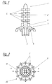
- Figures 1 and 2 is a first and in Figures 3 and 4, a second embodiment a mixing rotor shown.
- the mixing rotor 1 contains in essentially a rotor hub 2, on the inlet side a rotor disk 3 is arranged. On the back of the rotor disc are mixing blades 4 and subsequently mixing cams 5 arranged.
- the rotor hub on the input side a driver opening 6 for engagement with the driver of the mixer drive shaft on that on can be designed in various ways, e.g. square, hexagonal or cross-slit.
- the rotor disk On the input side, the rotor disk has chamber webs 7 which divide the rotor disk into chamber sections 8. This Sections serve the proportioned 180 ° offset alternate admission and further transport of the two mixing components. To avoid a jam of the components avoid, the webs 7 are shortened, i.e. not quite carried out continuously.
- the rotor disc also has one Collar 9 on which the one on the rotor housing attached sealing lip 34 is used. Between the rotor housing and the rotor disk circumference result from the webs 7 interrupted, annular gaps 10 through which the Components to the rear of the rotor disc and from there to the Mixing elements get into the cylinder housing part.
- FIGS. 3 and 4 show the mixing rotor 11 with a Rotor hub 12 on which a rotor disk 13 at the inlet is arranged. They are on the back of the rotor disc Mixing blades 4 and other mixing blades 4A and below the mixing cams 5 arranged.
- Figure 3A the Cross section of the mixing cams 5 and in Figure 3B Cross section of the mixing blades 4 shown.
- the rotor disk 13 On the input side, the rotor disk 13 has drivers which alternately differently outward extend, the drivers 15 protrude less to the outside than the drivers 14.
- the drivers 14 and 15 point tooth-shaped profile, each with a wing 15Y or 15Z on driver 15 offset with respect to the wings 14Y or 14Z are arranged on driver 14.
- the rotor disk input side is not in closed chamber sections 16 divided by the proportioned, alternate recording offset by 180 ° and the further transport of the two to be mixed Serve components and thus contribute to premixing.
- the Components can also come in from the inlets this embodiment only on the between the Carriers resulting annular gaps 17 between the rotor disc circumference and rotor housing on the Get back of the rotor disc. But it is also possible to provide annular gaps closer to the center, along with the peripheral or just such. Furthermore points the rotor disc has a collar 18 for receiving the sealing lip on.
- the mixing rotor 1 or 11 is in two parts Rotor housing arranged, which in Figures 5 to 8 is shown.
- the rotor housing 19 according to FIGS. 5 and 6 has a plate housing part 20 for receiving the Rotor disc 13 and a cylinder housing part 21 for receiving the rotor hub 12.
- On the bottom surface of the The plate housing part 20 is a first, outer stator comb 22 arranged, which consists of individual webs 23, the premixed components through the web spaces 24 get to the second, inner stator comb 25, the inner one Has webs 26 with spaces 27 through which premixed components to the mixing blades 4A, 4 and reach the mixing cam 5 to be broken up again by these and get mixed up.
- the plate housing part has furthermore a support surface 28, to which a bayonet ring 35 attacks.
- a rotor housing cover 29 is shown in FIGS. 7 and 8 shown, the rotor bearing 30 for receiving the Driver hub 31 and two identical inlets 32 and 33 having.
- the rotor housing cover 29 has a sealing lip 34.
- an assembled mixer is in section equal sized inlets shown with a Double cartridge or discharge device is connectable, the Containers an aspect ratio of 5: 1 and their Outlets have different diameters.
- outlets 37 and 38 are shown. The one The inlet 32 of the mixer is through the smaller outlet 37 and the other inlet 33 of the mixer is in the larger outlet 38 inserted, the mixer without previous orientation can be put on.
- FIG. 10 shows that the same mixer as in Figure 9 also with a double cartridge or Discharge device can be connected to the same outlets, the two inlets 32, 33 of the mixer into the Outlets 39, 40 can be inserted, also without previous orientation.
- the mixer is operated using a Bayonet rings 35 secured, this one too Thread nut ring can be.
- the use of the same Mixer is also for double cartridges or discharge devices with different cross-sectional ratios and outlet diameters as 1: 1 and 5: 1, e.g. 10: 1, possible.
Landscapes
- Chemical & Material Sciences (AREA)
- Chemical Kinetics & Catalysis (AREA)
- Health & Medical Sciences (AREA)
- Engineering & Computer Science (AREA)
- Mechanical Engineering (AREA)
- Life Sciences & Earth Sciences (AREA)
- Dentistry (AREA)
- Epidemiology (AREA)
- Oral & Maxillofacial Surgery (AREA)
- Animal Behavior & Ethology (AREA)
- General Health & Medical Sciences (AREA)
- Public Health (AREA)
- Veterinary Medicine (AREA)
- Mixers Of The Rotary Stirring Type (AREA)
- Processing And Handling Of Plastics And Other Materials For Molding In General (AREA)
- Accessories For Mixers (AREA)
- Processing Of Solid Wastes (AREA)
- Engine Equipment That Uses Special Cycles (AREA)
Abstract
Description
- Figur 1
- zeigt in einer Seitenansicht und teilweise geschnitten ein erstes Ausführungsbeispiel eines erfindungsgemässen Mischrotors,
- Figur 2
- zeigt den Mischrotor von Figur 1 von der Eingangsseite,
- Figur 3
- zeigt in einem Schnitt gemäss der Linie III-III in Figur 4 ein zweites Ausführungsbeispiel eines erfindungsgemässen Mischrotors,
- Figur 3A
- zeigt einen Schnitt gemäss der Linie IIIA-IIIA in Figur 3,
- Figur 3B
- zeigt einen Schnitt gemäss der Linie IIIB-IIIB in Figur 3,
- Figur 4
- zeigt den Mischrotor von Figur 3 von der Eingangsseite,
- Figur 5
- zeigt das Rotorgehäuse eines erfindungsgemässen Mischers gemäss Schnitt V-V in Fig. 6,
- Figur 6
- zeigt das Rotorgehäuse von Figur 5 von der Eingangsseite,
- Figur 7
- zeigt den Deckel des Rotorgehäuses der Figuren 5 und 6 gemäss Schnitt VII-VII in Fig. 8,
- Figur 8
- zeigt den Rotorgehäusedeckel von der Ausgangsseite,
- Figur 9
- zeigt einen Längsschnitt des zusammengebauten Mischers gemäss den Figuren 3-8 an Auslässen mit unterschiedlichen Durchmessern, und
- Figur 10
- zeigt einen Längsschnitt des zusammengebauten Mischers gemäss den Figuren 3-8 an Auslässen mit gleichem Durchmesser.
Claims (11)
- Dynamischer Mischer mit einem Rotorgehäuse, in dem ein drehbarer Mischrotor angeordnet ist, wobei das Rotorgehäuse (19) durch einen eingangsseitigen, tellerförmigen Deckel (29) abgeschlossen ist, an dem Einlässe (32, 33) für die zu mischenden Komponenten angeordnet sind, dadurch gekennzeichnet, dass der Mischrotor (1, 11), zur Vormischung der Komponenten, bei den Einlässen (32, 33) eine Rotorscheibe (3, 13) aufweist, deren eingangsseitige Oberfläche Mittel (7; 14, 15) zur Mitnahme der zu mischenden Komponenten aufweist und die mit Spälten (10, 17) versehen ist, die dem Durchtritt der Komponenten zur Rückseite der Rotorscheibe und zur Rotornabe (2, 12) dienen, an denen Mischelemente (4, 4A, 5) angeordnet sind.
- Dynamischer Mischer nach Anspruch 1, dadurch gekennzeichnet, dass die Spälte (10, 17) ringförmig und am Umfang der Rotorscheibe (3, 13) angeordnet sind.
- Dynamischer Mischer nach Anspruch 1 oder 2, dadurch gekennzeichnet, dass die Mittel zur Mitnahme der Komponenten Kammerstege (7) oder Mitnehmer (14, 15) sind, die Kammerabschnitte (8, 16) bilden.
- Dynamischer Mischer nach einem der Ansprüche 1 bis 3, dadurch gekennzeichnet, dass die Mitnehmer (14, 15) sich abwechslungsweise verschieden weit nach aussen erstrecken, wobei die kürzeren Mitnehmer (15) im Profil Flügel (15Y, 15Z) aufweisen, die versetzt zu den Flügeln (14Y, 14Z) am längeren Mitnehmer (14) angeordnet sind.
- Dynamischer Mischer nach einem der Ansprüche 1 bis 4, dadurch gekennzeichnet, dass das Rotorgehäuse (19) als Stator ausgebildet ist und ein Tellergehäuseteil (20) und ein Zylindergehäuseteil (21) aufweist und dass auf der Bodenfläche im Innern des Tellergehäuseteils mindestens ein Statorkamm (22, 25) angeordnet ist, durch dessen Zwischenräume (24, 27) die Komponenten zu den Mischelementen (4A, 4, 5) gelangen.
- Dynamischer Mischer nach Anspruch 5, dadurch gekennzeichnet, dass im Tellergehäuseteil (20) zwei konzentrisch angeordnete Statorkämme (22, 25) angeordnet sind.
- Dynamischer Mischer nach einem der Ansprüche 1 bis 6, dadurch gekennzeichnet, dass die Mischelemente Mischflügel (4, 4A) und kranzförmig angeordnete Mischnocken (5) enthalten.
- Dynamischer Mischer nach einem der Ansprüche 1 bis 7, dadurch gekennzeichnet, dass auf der Innenseite des Rotorgehäusedeckels (29) eine Dichtlippe (34) zur Dichtung der Mitnehmernabe (31) angeordnet ist.
- Dynamischer Mischer nach einem der Ansprüche 1 bis 8, dadurch gekennzeichnet, dass im Innern des Zylindergehäuseteils (21) weitere Statorelemente angebracht sind, um die Vermischung der Komponenten zu verbessern.
- Dynamischer Mischer nach einem der Ansprüche 1 bis 9, dadurch gekennzeichnet, dass er mittels eines Bajonett-Rings (35) am Auslassende einer Doppelkartusche oder eines Austraggerätes befestigbar ist.
- Dynamischer Mischer an einer Doppelkartusche oder an einem Austraggerät, dadurch gekennzeichnet, dass der Mischer zwei gleiche Einlässe (32, 33) aufweist und die Doppelkartusche oder das Austraggerät entweder Auslässe (39, 40), die den gleichen Durchmesser besitzen oder Auslässe (37, 38) aufweist, deren Durchmesser verschieden sind, wobei, ohne Vororientierung, die Einlässe (32, 33) entweder in die Auslässe (39, 40) einschiebbar sind oder der eine Einlass (32) über den kleineren Auslass (37) schiebbar und der andere Einlass (33) in den grösseren Auslass (38) steckbar ist.
Priority Applications (4)
| Application Number | Priority Date | Filing Date | Title |
|---|---|---|---|
| EP05016489A EP1595594B1 (de) | 1999-12-02 | 2000-05-18 | Dynamischer Mischer |
| US09/716,323 US6443612B1 (en) | 1999-12-02 | 2000-11-21 | Dynamic mixer |
| JP2000365195A JP4814423B2 (ja) | 1999-12-02 | 2000-11-30 | ダイナミックミキサ |
| US10/190,556 US6932243B2 (en) | 1999-12-02 | 2002-07-09 | Dispensing assembly with dynamic mixer |
Applications Claiming Priority (2)
| Application Number | Priority Date | Filing Date | Title |
|---|---|---|---|
| CH221099 | 1999-12-02 | ||
| CH221099 | 1999-12-02 |
Related Child Applications (1)
| Application Number | Title | Priority Date | Filing Date |
|---|---|---|---|
| EP05016489A Division EP1595594B1 (de) | 1999-12-02 | 2000-05-18 | Dynamischer Mischer |
Publications (3)
| Publication Number | Publication Date |
|---|---|
| EP1106243A2 true EP1106243A2 (de) | 2001-06-13 |
| EP1106243A3 EP1106243A3 (de) | 2003-01-08 |
| EP1106243B1 EP1106243B1 (de) | 2006-06-21 |
Family
ID=4228459
Family Applications (2)
| Application Number | Title | Priority Date | Filing Date |
|---|---|---|---|
| EP00810432A Expired - Lifetime EP1106243B1 (de) | 1999-12-02 | 2000-05-18 | Dynamischer Mischer. |
| EP05016489A Expired - Lifetime EP1595594B1 (de) | 1999-12-02 | 2000-05-18 | Dynamischer Mischer |
Family Applications After (1)
| Application Number | Title | Priority Date | Filing Date |
|---|---|---|---|
| EP05016489A Expired - Lifetime EP1595594B1 (de) | 1999-12-02 | 2000-05-18 | Dynamischer Mischer |
Country Status (4)
| Country | Link |
|---|---|
| EP (2) | EP1106243B1 (de) |
| AT (2) | ATE330700T1 (de) |
| DE (2) | DE50014149D1 (de) |
| ES (2) | ES2265903T3 (de) |
Cited By (6)
| Publication number | Priority date | Publication date | Assignee | Title |
|---|---|---|---|---|
| EP1510249A1 (de) * | 2003-09-01 | 2005-03-02 | GC Corporation | Mischer für Zahnabdruckmaterial |
| DE102004020410A1 (de) * | 2004-04-23 | 2005-12-01 | Heraeus Kulzer Gmbh | Dynamischer Mischer für strukturviskose Pasten |
| WO2007041878A1 (en) * | 2005-10-07 | 2007-04-19 | Sulzer Mixpac Ag | Dynamic mixer |
| US7287898B2 (en) | 2001-03-15 | 2007-10-30 | 3M Espe Ag | Dynamic mixer |
| CN101801511B (zh) * | 2007-09-10 | 2013-03-27 | 苏舍米克斯帕克有限公司 | 动力混合器 |
| CN108404707A (zh) * | 2018-04-20 | 2018-08-17 | 桐乡市远邦传感器有限公司 | 一种信箱装置 |
Families Citing this family (3)
| Publication number | Priority date | Publication date | Assignee | Title |
|---|---|---|---|---|
| US8322909B2 (en) | 2004-09-22 | 2012-12-04 | 3M Deutschland Gmbh | Mixer for multi-component pastes, kit, and method of mixing paste components |
| EP1640060A1 (de) | 2004-09-22 | 2006-03-29 | 3M Espe Ag | Mischer für Mehrkomponentenpasten, Bausatz, und Verfahren zum Mischen von Pasten |
| RU171021U1 (ru) * | 2017-01-10 | 2017-05-17 | Федеральное государственное бюджетное образовательное учреждение высшего образования "Волгоградский государственный технический университет" (ВолгГТУ) | Мешалка |
Family Cites Families (8)
| Publication number | Priority date | Publication date | Assignee | Title |
|---|---|---|---|---|
| US3051455A (en) * | 1960-07-25 | 1962-08-28 | Gen Electric | Mixing nozzle |
| BE625883A (de) * | 1961-12-08 | |||
| JPS56118728A (en) * | 1980-02-26 | 1981-09-17 | Fukushima Tadao | Continuous stirring apparatus |
| DE9017323U1 (de) * | 1990-12-21 | 1992-04-16 | Thera Patent GmbH & Co KG Gesellschaft für industrielle Schutzrechte, 8031 Seefeld | Dynamischer Mischer |
| DE4235736C1 (de) * | 1992-10-23 | 1994-03-24 | Bergmann Franz Josef | Vorrichtung zum Mischen und Austragen pastöser Massen |
| DE59407962D1 (de) * | 1994-01-19 | 1999-04-22 | Wilhelm A Keller | Mischer |
| DE69716887T2 (de) * | 1997-06-18 | 2003-03-20 | Wilhelm A. Keller | Mischer |
| DE19947331C2 (de) * | 1999-10-01 | 2002-02-28 | 3M Espe Ag | Dynamischer Mischer |
-
2000
- 2000-05-18 AT AT00810432T patent/ATE330700T1/de not_active IP Right Cessation
- 2000-05-18 EP EP00810432A patent/EP1106243B1/de not_active Expired - Lifetime
- 2000-05-18 ES ES00810432T patent/ES2265903T3/es not_active Expired - Lifetime
- 2000-05-18 ES ES05016489T patent/ES2282959T3/es not_active Expired - Lifetime
- 2000-05-18 DE DE50014149T patent/DE50014149D1/de not_active Expired - Lifetime
- 2000-05-18 DE DE50013039T patent/DE50013039D1/de not_active Expired - Lifetime
- 2000-05-18 EP EP05016489A patent/EP1595594B1/de not_active Expired - Lifetime
- 2000-05-18 AT AT05016489T patent/ATE355891T1/de not_active IP Right Cessation
Cited By (12)
| Publication number | Priority date | Publication date | Assignee | Title |
|---|---|---|---|---|
| US7287898B2 (en) | 2001-03-15 | 2007-10-30 | 3M Espe Ag | Dynamic mixer |
| US7674033B2 (en) | 2001-03-15 | 2010-03-09 | 3M Espe Ag | Dynamic mixer |
| EP1510249A1 (de) * | 2003-09-01 | 2005-03-02 | GC Corporation | Mischer für Zahnabdruckmaterial |
| US7172338B2 (en) | 2003-09-01 | 2007-02-06 | Gc Corporation | Stirring mixer for dental impression material |
| AU2004205312B2 (en) * | 2003-09-01 | 2009-01-29 | Gc Corporation | Stirring mixer for dental impression material |
| DE102004020410A1 (de) * | 2004-04-23 | 2005-12-01 | Heraeus Kulzer Gmbh | Dynamischer Mischer für strukturviskose Pasten |
| DE102004020410B4 (de) * | 2004-04-23 | 2007-08-02 | Heraeus Kulzer Gmbh | Dynamischer Mischer für strukturviskose Pasten |
| WO2007041878A1 (en) * | 2005-10-07 | 2007-04-19 | Sulzer Mixpac Ag | Dynamic mixer |
| AU2006301860B2 (en) * | 2005-10-07 | 2010-11-11 | Sulzer Mixpac Ag | Dynamic mixer |
| US8313232B2 (en) | 2005-10-07 | 2012-11-20 | Sulzer Mixpac Ag | Dynamic mixer |
| CN101801511B (zh) * | 2007-09-10 | 2013-03-27 | 苏舍米克斯帕克有限公司 | 动力混合器 |
| CN108404707A (zh) * | 2018-04-20 | 2018-08-17 | 桐乡市远邦传感器有限公司 | 一种信箱装置 |
Also Published As
| Publication number | Publication date |
|---|---|
| EP1106243A3 (de) | 2003-01-08 |
| EP1106243B1 (de) | 2006-06-21 |
| EP1595594A1 (de) | 2005-11-16 |
| ATE355891T1 (de) | 2007-03-15 |
| ATE330700T1 (de) | 2006-07-15 |
| DE50013039D1 (de) | 2006-08-03 |
| ES2265903T3 (es) | 2007-03-01 |
| EP1595594B1 (de) | 2007-03-07 |
| ES2282959T3 (es) | 2007-10-16 |
| DE50014149D1 (de) | 2007-04-19 |
Similar Documents
| Publication | Publication Date | Title |
|---|---|---|
| EP0971787B1 (de) | Dynamischer mischer für zahnärztliche abdruckmassen | |
| EP1110599B1 (de) | Dynamischer Mischer für zahnärztliche Abdruckmassen | |
| EP1099470B1 (de) | Vorrichtung zum Vermischen zweier pastöser Massen, insbesondere zum Vermischen einer Dental-Abformmasse mit einer Katalysatormasse | |
| DE19947331C2 (de) | Dynamischer Mischer | |
| EP2755769B1 (de) | Vorrichtung zum mischen | |
| EP2659958A1 (de) | Gezahntes Mischelement | |
| WO2011151435A1 (de) | Drehantriebsausbildung | |
| DE2901137A1 (de) | Selbstsicherndes befestigungselement sowie presswerkzeug zu dessen herstellung | |
| DE602005000098T2 (de) | Dynamische Durchfluss-Mischvorrichtung | |
| EP1768771A1 (de) | Mischvorrichtung | |
| EP0013721B1 (de) | Aufrührorgan für mit Farben oder Lacken gefüllte zylindrische Behälter | |
| EP1106243A2 (de) | Dynamischer Mischer. | |
| DE102015106419A1 (de) | Rührwerk und Behälter mit Rührwerk | |
| DE1276986B (de) | Pflugscharaehnliches Mischwerkzeug | |
| EP1072309A2 (de) | Zweikomponentenkartusche | |
| DE2643560C2 (de) | Rührvorrichtung | |
| DE60100554T2 (de) | Katzenstreubehälter | |
| DE2513577C3 (de) | Kontinuierlich arbeitender Mischer für plastische Massen | |
| DE2216986C3 (de) | Mischvorrichtung | |
| DE102004060621B4 (de) | Statikmischelement zum Mischen fliessfähiger Massen | |
| DE2007309C3 (de) | Vorrichtung zum Mischen oder Trocknen eines oder mehrerer pulver-, granulat- oder pastenförmiger Stoffe | |
| DE10104580B4 (de) | Fräswerkzeug | |
| DD294197A5 (de) | Kompakter kolbenvibrator | |
| DE102013002290A1 (de) | Mischvorrichtung für Zweikomponentenkartuschen | |
| EP0896834A2 (de) | Dispergiervorrichtung zum allseitigen Benetzen von Primärteilchen pulvriger Stoffe |
Legal Events
| Date | Code | Title | Description |
|---|---|---|---|
| PUAI | Public reference made under article 153(3) epc to a published international application that has entered the european phase |
Free format text: ORIGINAL CODE: 0009012 |
|
| AK | Designated contracting states |
Kind code of ref document: A2 Designated state(s): AT BE CH CY DE DK ES FI FR GB GR IE IT LI LU MC NL PT SE |
|
| AX | Request for extension of the european patent |
Free format text: AL;LT;LV;MK;RO;SI |
|
| PUAL | Search report despatched |
Free format text: ORIGINAL CODE: 0009013 |
|
| AK | Designated contracting states |
Kind code of ref document: A3 Designated state(s): AT BE CH CY DE DK ES FI FR GB GR IE IT LI LU MC NL PT SE |
|
| AX | Request for extension of the european patent |
Free format text: AL;LT;LV;MK;RO;SI |
|
| RIC1 | Information provided on ipc code assigned before grant |
Free format text: 7B 01F 13/00 A, 7B 01F 7/00 B, 7B 01F 7/16 B, 7A 61C 9/00 B |
|
| 17P | Request for examination filed |
Effective date: 20030708 |
|
| AKX | Designation fees paid |
Designated state(s): AT BE CH CY DE DK ES FI FR GB GR IE IT LI LU MC NL PT SE |
|
| RAP1 | Party data changed (applicant data changed or rights of an application transferred) |
Owner name: MIXPAC SYSTEMS AG |
|
| RIN1 | Information on inventor provided before grant (corrected) |
Inventor name: MIXPAC SYSTEMS AG |
|
| 17Q | First examination report despatched |
Effective date: 20050201 |
|
| RIN1 | Information on inventor provided before grant (corrected) |
Inventor name: KELLER, WILHELM A. |
|
| GRAP | Despatch of communication of intention to grant a patent |
Free format text: ORIGINAL CODE: EPIDOSNIGR1 |
|
| GRAS | Grant fee paid |
Free format text: ORIGINAL CODE: EPIDOSNIGR3 |
|
| GRAA | (expected) grant |
Free format text: ORIGINAL CODE: 0009210 |
|
| AK | Designated contracting states |
Kind code of ref document: B1 Designated state(s): AT BE CH CY DE DK ES FI FR GB GR IE IT LI LU MC NL PT SE |
|
| PG25 | Lapsed in a contracting state [announced via postgrant information from national office to epo] |
Ref country code: IT Free format text: LAPSE BECAUSE OF FAILURE TO SUBMIT A TRANSLATION OF THE DESCRIPTION OR TO PAY THE FEE WITHIN THE PRE;WARNING: LAPSES OF ITALIAN PATENTS WITH EFFECTIVE DATE BEFORE 2007 MAY HAVE OCCURRED AT ANY TIME BEFORE 2007. THE CORRECT EFFECTIVE DATE MAY BE DIFFERENT FROM THE ONE RECORDED.SCRIBED TIME-LIMIT Effective date: 20060621 Ref country code: FI Free format text: LAPSE BECAUSE OF FAILURE TO SUBMIT A TRANSLATION OF THE DESCRIPTION OR TO PAY THE FEE WITHIN THE PRESCRIBED TIME-LIMIT Effective date: 20060621 Ref country code: IE Free format text: LAPSE BECAUSE OF FAILURE TO SUBMIT A TRANSLATION OF THE DESCRIPTION OR TO PAY THE FEE WITHIN THE PRESCRIBED TIME-LIMIT Effective date: 20060621 Ref country code: NL Free format text: LAPSE BECAUSE OF FAILURE TO SUBMIT A TRANSLATION OF THE DESCRIPTION OR TO PAY THE FEE WITHIN THE PRESCRIBED TIME-LIMIT Effective date: 20060621 |
|
| REG | Reference to a national code |
Ref country code: GB Ref legal event code: FG4D Free format text: NOT ENGLISH |
|
| REG | Reference to a national code |
Ref country code: CH Ref legal event code: EP |
|
| REG | Reference to a national code |
Ref country code: CH Ref legal event code: NV Representative=s name: AMMANN PATENTANWAELTE AG BERN |
|
| REG | Reference to a national code |
Ref country code: IE Ref legal event code: FG4D Free format text: LANGUAGE OF EP DOCUMENT: GERMAN |
|
| REF | Corresponds to: |
Ref document number: 50013039 Country of ref document: DE Date of ref document: 20060803 Kind code of ref document: P |
|
| GBT | Gb: translation of ep patent filed (gb section 77(6)(a)/1977) |
Effective date: 20060814 |
|
| PG25 | Lapsed in a contracting state [announced via postgrant information from national office to epo] |
Ref country code: DK Free format text: LAPSE BECAUSE OF FAILURE TO SUBMIT A TRANSLATION OF THE DESCRIPTION OR TO PAY THE FEE WITHIN THE PRESCRIBED TIME-LIMIT Effective date: 20060921 |
|
| REG | Reference to a national code |
Ref country code: SE Ref legal event code: TRGR |
|
| PG25 | Lapsed in a contracting state [announced via postgrant information from national office to epo] |
Ref country code: PT Free format text: LAPSE BECAUSE OF FAILURE TO SUBMIT A TRANSLATION OF THE DESCRIPTION OR TO PAY THE FEE WITHIN THE PRESCRIBED TIME-LIMIT Effective date: 20061121 |
|
| NLV1 | Nl: lapsed or annulled due to failure to fulfill the requirements of art. 29p and 29m of the patents act | ||
| ET | Fr: translation filed | ||
| REG | Reference to a national code |
Ref country code: IE Ref legal event code: FD4D |
|
| REG | Reference to a national code |
Ref country code: ES Ref legal event code: FG2A Ref document number: 2265903 Country of ref document: ES Kind code of ref document: T3 |
|
| PLBE | No opposition filed within time limit |
Free format text: ORIGINAL CODE: 0009261 |
|
| STAA | Information on the status of an ep patent application or granted ep patent |
Free format text: STATUS: NO OPPOSITION FILED WITHIN TIME LIMIT |
|
| 26N | No opposition filed |
Effective date: 20070322 |
|
| BERE | Be: lapsed |
Owner name: MIXPAC SYSTEMS A.G. Effective date: 20070531 |
|
| PG25 | Lapsed in a contracting state [announced via postgrant information from national office to epo] |
Ref country code: MC Free format text: LAPSE BECAUSE OF NON-PAYMENT OF DUE FEES Effective date: 20070531 |
|
| PG25 | Lapsed in a contracting state [announced via postgrant information from national office to epo] |
Ref country code: BE Free format text: LAPSE BECAUSE OF NON-PAYMENT OF DUE FEES Effective date: 20070531 |
|
| PG25 | Lapsed in a contracting state [announced via postgrant information from national office to epo] |
Ref country code: GR Free format text: LAPSE BECAUSE OF FAILURE TO SUBMIT A TRANSLATION OF THE DESCRIPTION OR TO PAY THE FEE WITHIN THE PRESCRIBED TIME-LIMIT Effective date: 20060922 |
|
| PG25 | Lapsed in a contracting state [announced via postgrant information from national office to epo] |
Ref country code: AT Free format text: LAPSE BECAUSE OF NON-PAYMENT OF DUE FEES Effective date: 20070518 |
|
| PG25 | Lapsed in a contracting state [announced via postgrant information from national office to epo] |
Ref country code: LU Free format text: LAPSE BECAUSE OF NON-PAYMENT OF DUE FEES Effective date: 20070518 Ref country code: CY Free format text: LAPSE BECAUSE OF FAILURE TO SUBMIT A TRANSLATION OF THE DESCRIPTION OR TO PAY THE FEE WITHIN THE PRESCRIBED TIME-LIMIT Effective date: 20060621 |
|
| REG | Reference to a national code |
Ref country code: CH Ref legal event code: NV Representative=s name: DR. GRAF AND PARTNER AG INTELLECTUAL PROPERTY, CH Ref country code: CH Ref legal event code: PFUS Owner name: SULZER MIXPAC AG, CH Free format text: FORMER OWNER: MIXPAC SYSTEMS AG, CH |
|
| PGFP | Annual fee paid to national office [announced via postgrant information from national office to epo] |
Ref country code: SE Payment date: 20150520 Year of fee payment: 16 |
|
| REG | Reference to a national code |
Ref country code: FR Ref legal event code: PLFP Year of fee payment: 17 |
|
| PG25 | Lapsed in a contracting state [announced via postgrant information from national office to epo] |
Ref country code: SE Free format text: LAPSE BECAUSE OF NON-PAYMENT OF DUE FEES Effective date: 20160519 |
|
| REG | Reference to a national code |
Ref country code: FR Ref legal event code: PLFP Year of fee payment: 18 |
|
| PGFP | Annual fee paid to national office [announced via postgrant information from national office to epo] |
Ref country code: ES Payment date: 20170627 Year of fee payment: 18 |
|
| REG | Reference to a national code |
Ref country code: FR Ref legal event code: PLFP Year of fee payment: 19 |
|
| PGFP | Annual fee paid to national office [announced via postgrant information from national office to epo] |
Ref country code: DE Payment date: 20180522 Year of fee payment: 19 Ref country code: CH Payment date: 20180523 Year of fee payment: 19 |
|
| PGFP | Annual fee paid to national office [announced via postgrant information from national office to epo] |
Ref country code: IT Payment date: 20180530 Year of fee payment: 19 Ref country code: FR Payment date: 20180522 Year of fee payment: 19 |
|
| PGFP | Annual fee paid to national office [announced via postgrant information from national office to epo] |
Ref country code: GB Payment date: 20180518 Year of fee payment: 19 |
|
| REG | Reference to a national code |
Ref country code: ES Ref legal event code: FD2A Effective date: 20190913 |
|
| PG25 | Lapsed in a contracting state [announced via postgrant information from national office to epo] |
Ref country code: ES Free format text: LAPSE BECAUSE OF NON-PAYMENT OF DUE FEES Effective date: 20180519 |
|
| REG | Reference to a national code |
Ref country code: DE Ref legal event code: R119 Ref document number: 50013039 Country of ref document: DE |
|
| REG | Reference to a national code |
Ref country code: CH Ref legal event code: PL |
|
| GBPC | Gb: european patent ceased through non-payment of renewal fee |
Effective date: 20190518 |
|
| PG25 | Lapsed in a contracting state [announced via postgrant information from national office to epo] |
Ref country code: CH Free format text: LAPSE BECAUSE OF NON-PAYMENT OF DUE FEES Effective date: 20190531 Ref country code: LI Free format text: LAPSE BECAUSE OF NON-PAYMENT OF DUE FEES Effective date: 20190531 |
|
| PG25 | Lapsed in a contracting state [announced via postgrant information from national office to epo] |
Ref country code: IT Free format text: LAPSE BECAUSE OF NON-PAYMENT OF DUE FEES Effective date: 20190518 Ref country code: DE Free format text: LAPSE BECAUSE OF NON-PAYMENT OF DUE FEES Effective date: 20191203 Ref country code: GB Free format text: LAPSE BECAUSE OF NON-PAYMENT OF DUE FEES Effective date: 20190518 |
|
| PG25 | Lapsed in a contracting state [announced via postgrant information from national office to epo] |
Ref country code: FR Free format text: LAPSE BECAUSE OF NON-PAYMENT OF DUE FEES Effective date: 20190531 |