EP1106859B1 - Procédé de fabrication des plaques de support pour garnitures de frein - Google Patents
Procédé de fabrication des plaques de support pour garnitures de frein Download PDFInfo
- Publication number
- EP1106859B1 EP1106859B1 EP99123979A EP99123979A EP1106859B1 EP 1106859 B1 EP1106859 B1 EP 1106859B1 EP 99123979 A EP99123979 A EP 99123979A EP 99123979 A EP99123979 A EP 99123979A EP 1106859 B1 EP1106859 B1 EP 1106859B1
- Authority
- EP
- European Patent Office
- Prior art keywords
- support plate
- powder
- friction material
- prominences
- support
- Prior art date
- Legal status (The legal status is an assumption and is not a legal conclusion. Google has not performed a legal analysis and makes no representation as to the accuracy of the status listed.)
- Expired - Lifetime
Links
Images

Classifications
-
- F—MECHANICAL ENGINEERING; LIGHTING; HEATING; WEAPONS; BLASTING
- F16—ENGINEERING ELEMENTS AND UNITS; GENERAL MEASURES FOR PRODUCING AND MAINTAINING EFFECTIVE FUNCTIONING OF MACHINES OR INSTALLATIONS; THERMAL INSULATION IN GENERAL
- F16D—COUPLINGS FOR TRANSMITTING ROTATION; CLUTCHES; BRAKES
- F16D69/00—Friction linings; Attachment thereof; Selection of coacting friction substances or surfaces
- F16D69/04—Attachment of linings
- F16D2069/0425—Attachment methods or devices
- F16D2069/0441—Mechanical interlocking, e.g. roughened lining carrier, mating profiles on friction material and lining carrier
-
- F—MECHANICAL ENGINEERING; LIGHTING; HEATING; WEAPONS; BLASTING
- F16—ENGINEERING ELEMENTS AND UNITS; GENERAL MEASURES FOR PRODUCING AND MAINTAINING EFFECTIVE FUNCTIONING OF MACHINES OR INSTALLATIONS; THERMAL INSULATION IN GENERAL
- F16D—COUPLINGS FOR TRANSMITTING ROTATION; CLUTCHES; BRAKES
- F16D69/00—Friction linings; Attachment thereof; Selection of coacting friction substances or surfaces
- F16D69/04—Attachment of linings
- F16D2069/0425—Attachment methods or devices
- F16D2069/0483—Lining or lining carrier material shaped in situ
-
- F—MECHANICAL ENGINEERING; LIGHTING; HEATING; WEAPONS; BLASTING
- F16—ENGINEERING ELEMENTS AND UNITS; GENERAL MEASURES FOR PRODUCING AND MAINTAINING EFFECTIVE FUNCTIONING OF MACHINES OR INSTALLATIONS; THERMAL INSULATION IN GENERAL
- F16D—COUPLINGS FOR TRANSMITTING ROTATION; CLUTCHES; BRAKES
- F16D69/00—Friction linings; Attachment thereof; Selection of coacting friction substances or surfaces
- F16D69/04—Attachment of linings
- F16D2069/0425—Attachment methods or devices
- F16D2069/0491—Tools, machines, processes
Definitions
- the invention relates to a method for producing carrier plates for material blocks, in particular for friction material blocks, according to the preamble of claim 1.
- a friction lining for disc brakes especially for road vehicles and rail vehicles is known.
- This friction lining is formed in one or more parts and consists of a mounted on a support plate or support plate block of a pressed friction material.
- the support plate has on the side bearing the friction material a sintered support bed of individual, with the friction material non-positively and positively forming moldings with undercuts, Recoveries od. Like. On. On the support bed of the pressed-friction material in block form under the undercuts, recoveries od. Like.
- the individual molded body is attached.
- Such friction linings which have long been proven in their practical use, often still require the use of an intermediate layer between the support bed and the Reibmaterialblock.
- This intermediate layer has hitherto been formed as a binder film or as an adhesive, but it is associated with various disadvantages, so that it is desirable to provide a possibility that this intermediate layer can be dispensed with.
- the bonding of the friction material to the carrier sheet requires relatively long service lives in the production of brake pads by the heat treatment of the adhesive, which leads to a lower production number. These service lives are required in order to achieve a good bonding of the friction material to the carrier sheet. If the service life is shortened, then poor adhesive bonds are obtained because no complete heat transfer is achieved by the adhesive. In addition, when using adhesives, the carrier sheet must be pretreated.
- the disadvantages resulting from the application of paint layers are avoided according to EP 0 442 052 A1 in that a galvanic metal coating is applied to the rough surface of the carrier plate before the friction material is pressed onto the carrier plate. The interaction of rough ground (support bed) and galvanic coating leads to a high corrosion protection for the support plate, while the rough ground causes the adhesion between the friction material and the carrier plate, since the galvanic coating follows the contour of the rough ground.
- the friction lining arrangement is prepared on the so prepared Metal sheet, the powdered friction material together with a binder using a mold using heat and pressure sintered so that the powdery mixture is pressed into the space between the wire mesh and the metal sheet.
- the metal sheet which forms the support plate exposed to heat, and indeed by the attachment of the wire mesh, which has the function of a support bed here.
- EP-A-0 626 228 One method of altering the surface of a workpiece to be bonded to another element is described in EP-A-0 626 228.
- This method consists of exposing individual locations of the surface of the workpiece to an energy beam, thereby exposing each beam-exposed site Material of the workpiece is melted by the action of the energy beam and thereby displaced laterally, so that then obtained after obtaining the heated material, a recess in the workpiece, which is surrounded by a region of solidified material, the wall-like from the surface of the workpiece rises and forms a necked-in area. It is created in this way a surface structure.
- This method assumes that the surface to be treated workpiece must have a large thickness in order to form the recesses in the Surface of the workpiece and the surface elevations sufficient material to have. With this method, the structure of the material of the workpiece is intervened, which leads to a change in the physical and mechanical properties of the workpiece.
- EP-A-0 581 988 describes a brake pad and a method for its production, as well as magnetic track brake for road and rail vehicles, in particular for rail vehicles with high and high speeds.
- the brake pad consists of one or more parts formed, pressed on a support body Reibtechniksttoffblock, wherein at least one friction material block on several, not lying in a plane, adjacent surface pieces of parts of the cast support body is positively and / or positively included.
- the friction material block is mounted on a support plate, which on the friction material block bearing side or on both sides depending on a sintered support bed of individual with the friction material block form-fitting and form-fitting moldings with undercuts, recoveries o. The like.
- Rauhground wherein on the support bed of pressed-on friction material block is filled under the undercuts, confiscation of the individual moldings.
- the inventive method is that by means of a nozzle, a mixture of carrier gas and metal powder is applied to the surface of the support plate to form a support bed with separate, spaced apart material increases as a surface structure, the material increases excluding thermal treatment of the entire support plate by means of local or sections energy acting on the support plate, in particular radiant energy, are generated successively or parallel to one another, wherein the material used for the support plate metal, metal alloys, hard plastic, glass or ceramic is used.
- the material increases from steel, metal, which may contain carbides and / or nitrides, ceramic, glass or a hard plastic, z. B. a thermosetting plastic.
- the material increases are preferably applied grid-like manner on the carrier plate. It is advantageous to preheat the carrier plate prior to forming the material increases.
- the material increases by sintering of powder or by powder coating with laser beam, flame jet or plasma jet, applied, there is the possibility to form the support bed also curved in space, curved or deformed surfaces of the support plate without difficulty.
- powder coating with laser beam there is the advantage that little heat energy is introduced into the carrier plate, so that even thin or thin-walled carrier plates to take without damage due to thermal overload can be provided with the support bed according to the invention.
- metal hydrides or carbides are used as additives to the above-mentioned materials.
- the sintering of the powder with respect to the carrier plate can take place in sections.
- the block of material is pressed into the surface structure of the support bed.
- a ceramic intermediate layer is applied to the support bed before the application of the material block.
- This intermediate layer acts as an insulating layer.
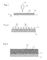
- a mixture of carrier gas and metal powder 12 is applied to the surface of a carrier plate 14 by means of a nozzle 10, so that a holding bed 16 is formed (FIG. 1).
- the nozzle 10 is moved, for example, computer-controlled on the support plate 14 and carries the powder 12 grid-like material increases 20 on the surface of the support plate 14.
- the sprayed-on powder 12 is structured (FIG. 2).
- the entire support plate 14 not only individual portions of the support plate 14 are successively subjected to a temperature treatment, so that there is no strong thermal stress on the entire support plate 14.
- the application of the powder 12 by means of the nozzle 10 is additionally assisted by the action of a laser, flame or plasma jet.
- a friction material block 22 is pressed onto the support bed 16 of the support plate 14 and results in the brake pad 100 shown in Fig. 3.
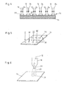
- the powder 12 is applied together with an energy 24 introduced locally at the location of the powder 12 in such a way that material increases 20 which are firmly connected to the surface of the carrier plate 14 (FIG. 4).
- the material elevations 20 are formed individually and successively on the surface of the carrier plate 14 (FIG. 5). through the introduced energy, a discrete accumulation of powder applied to the carrier plate 14 is processed to a surface structure of the carrier plate 14 with material elevations 20.
- the powder is preferably applied to the support plate 14 in a gas flow, so that there is no partial accumulation.
- the material increases 20 are formed by the entrained with the gas stream particles of the powder.
- the application of the powder 12 is carried out, for example, as shown in Fig. 6, by means of the nozzle 10 and a laser 26, such as a neodymium laser, which are combined in a functional unit for laser powder coating and, for example, computer controlled over the support plate 14.
- a laser 26 such as a neodymium laser
- the laser 26 has the particular advantage that targeted and only locally a heat input into the support plate 14 takes place. This considerably reduces the thermal load on the carrier plate 14 and makes it possible to use even previously unusable thermally sensitive materials as a carrier plate with a holding bed.
- the surface of the support plate 14 is increased.
- the area of the material increases 20, which serve as a connection to the friction material block only the surface of the support plate 14 is slightly changed, but a change in the material of the support plate with respect to mechanical and physical properties is effectively avoided.
- the laser 26 it is also possible to use another energy source, such as a flame radiator, plasma radiator or the like.
- the energy source only has to have the properties of applying or generating heat energy selectively locally or in a predetermined manner in a locally limited manner.
- the material elevations 20 are formed in a mushroom-like manner, so that a mechanically particularly strong bond between the carrier plate 14 and the friction material block 22 not shown in FIG. 7 results from corresponding undercuts on the material elevations.
Landscapes
- Engineering & Computer Science (AREA)
- General Engineering & Computer Science (AREA)
- Mechanical Engineering (AREA)
- Braking Arrangements (AREA)
Claims (10)
- Procédé de fabrication des plaques de support pour blocs de matériau de friction (22), comme garnitures de frein pour véhicules sur rails et non montés sur rails, au moins un lit de support (16) pour le bloc de matériau de friction étant formé pour réaliser une connexion entre la plaque de support et le bloc de matériau de friction (22),
caractérisé en ce
qu'un mélange de gaz porteur et de poudre métallique (12) est appliqué comme structure de surface au moyen d'une tuyère (10) sur la surface de la plaque de support (14) pour former un lit de support (16) avec des rehaussements de matériau séparés (20), espacés les uns des autres, les rehaussements de matériau étant produits les uns après les autres ou parallèlement les uns aux autres en excluant un traitement thermique de l'ensemble de la plaque de support (14) au moyen d'énergie agissant localement ou par section sur la plaque de support (14), en particulier d'énergie de rayonnement, du métal, des alliages de métal, du plastique dur, du verre ou de la céramique étant utilisée comme matériau pour la plaque de support (14). - Procédé selon la revendication 1,
caractérisé en ce
que les rehaussements de matériau (20) sont produits par frittage de poudre ou au moyen d'une enduction de poudre avec un faisceau laser, un jet de flamme ou un jet de plasma ou d'autres sources d'énergie appropriées ou par injection par faisceaux laser dans le matériau de la plaque de support (14). - Procédé selon la revendication 2,
caractérisé en ce
que des hydrures de métal et/ou des carbures et/ou des nitrures sont contenus dans la poudre. - Procédé selon l'une des revendications 2 et 3,
caractérisé en ce
que le frittage de la poudre se fait par section sur la plaque de support (14). - Procédé selon l'une des revendications 2 à 4,
caractérisé en ce
que les rehaussements de matériau (20) sont configurés de type champignon sur la plaque de support (14). - Procédé selon l'une des revendications 2 à 5,
caractérisé en ce
que les rehaussements de matériau (20) sont fabriqués en acier, en métal qui contient des carbures et/ou nitrures, de la céramique, du verre ou des plastiques durs. - Procédé selon l'une des revendications 1 à 6,
caractérisé en ce
que le bloc de matériau de friction est pressé dans la structure de surface du lit de support (16). - Procédé selon l'une des revendications 1 à 7,
caractérisé en ce
qu'une couche intermédiaire céramique est appliquée avant l'application du bloc de matériau de friction (22) sur le lit de support (16). - Procédé selon l'une des revendications 1 à 8,
caractérisé en ce
que les rehaussements de matériau (20) sont appliqués à la manière d'une grille sur la plaque de support (14). - Procédé selon l'une des revendications 1 à 9,
caractérisé en ce
que la plaque de support (14) est préchauffée avant la formation du lit de support (16).
Priority Applications (16)
| Application Number | Priority Date | Filing Date | Title |
|---|---|---|---|
| ES05024253T ES2275255T3 (es) | 1999-12-07 | 1999-12-07 | Placa portadora para bloques de material de friccion para forros de freno para vehiculos sobre carriles y vehiculos sobre carriles y vehiculos que no van por carriles. |
| AT06015958T ATE404803T1 (de) | 1999-12-07 | 1999-12-07 | Bremsbelag für schienen- und schienenungebundene fahrzeuge |
| ES99123979T ES2264237T3 (es) | 1999-12-07 | 1999-12-07 | Procedimiento para la fabricacion de placas de soporte para forros de freno. |
| AT05024175T ATE350600T1 (de) | 1999-12-07 | 1999-12-07 | Bremsbelag für schienen- und schienenungebundene fahrzeuge |
| EP05024253A EP1621792B1 (fr) | 1999-12-07 | 1999-12-07 | Plaque de support pour matériau de friction pour garnitures de frein pour véhicules sur rails ou roulant sur rails |
| DE59913967T DE59913967D1 (de) | 1999-12-07 | 1999-12-07 | Trägerplatte für Reibmaterialblöcke für Bremsbeläge für Schienen- und schienenungebundene Fahrzeuge |
| DE59914133T DE59914133D1 (de) | 1999-12-07 | 1999-12-07 | Bremsbelag für Schienen- und schienenungebundene Fahrzeuge |
| ES05024175T ES2280066T3 (es) | 1999-12-07 | 1999-12-07 | Forro de freno para vehiculos sobre carriles y no guiados por carriles. |
| AT05024253T ATE344404T1 (de) | 1999-12-07 | 1999-12-07 | Trägerplatte für reibmaterialblöcke für bremsbeläge für schienen- und schienenungebundene fahrzeuge |
| DE59914834T DE59914834D1 (de) | 1999-12-07 | 1999-12-07 | Bremsbelag für schienen- und schienenungebundene Fahrzeuge |
| EP06015958A EP1741952B1 (fr) | 1999-12-07 | 1999-12-07 | Garniture de frein pour véhicules sur rails et pas roulant sur rails |
| AT99123979T ATE328219T1 (de) | 1999-12-07 | 1999-12-07 | Verfahren zur herstellung von trägerplatten für bremsbeläge |
| EP05024175A EP1624218B1 (fr) | 1999-12-07 | 1999-12-07 | Garniture de frein pour véhicules sur rails et roulant sur rails |
| EP99123979A EP1106859B1 (fr) | 1999-12-07 | 1999-12-07 | Procédé de fabrication des plaques de support pour garnitures de frein |
| ES06015958T ES2311255T3 (es) | 1999-12-07 | 1999-12-07 | Guarnicion de freno para vehiculos guiados por carriles y no guiados por carriles. |
| DE59913492T DE59913492D1 (de) | 1999-12-07 | 1999-12-07 | Verfahren zur Herstellung von Trägerplatten für Bremsbeläge |
Applications Claiming Priority (1)
| Application Number | Priority Date | Filing Date | Title |
|---|---|---|---|
| EP99123979A EP1106859B1 (fr) | 1999-12-07 | 1999-12-07 | Procédé de fabrication des plaques de support pour garnitures de frein |
Related Child Applications (2)
| Application Number | Title | Priority Date | Filing Date |
|---|---|---|---|
| EP05024253A Division EP1621792B1 (fr) | 1999-12-07 | 1999-12-07 | Plaque de support pour matériau de friction pour garnitures de frein pour véhicules sur rails ou roulant sur rails |
| EP05024175A Division EP1624218B1 (fr) | 1999-12-07 | 1999-12-07 | Garniture de frein pour véhicules sur rails et roulant sur rails |
Publications (2)
| Publication Number | Publication Date |
|---|---|
| EP1106859A1 EP1106859A1 (fr) | 2001-06-13 |
| EP1106859B1 true EP1106859B1 (fr) | 2006-05-31 |
Family
ID=8239517
Family Applications (4)
| Application Number | Title | Priority Date | Filing Date |
|---|---|---|---|
| EP05024175A Expired - Lifetime EP1624218B1 (fr) | 1999-12-07 | 1999-12-07 | Garniture de frein pour véhicules sur rails et roulant sur rails |
| EP05024253A Expired - Lifetime EP1621792B1 (fr) | 1999-12-07 | 1999-12-07 | Plaque de support pour matériau de friction pour garnitures de frein pour véhicules sur rails ou roulant sur rails |
| EP99123979A Expired - Lifetime EP1106859B1 (fr) | 1999-12-07 | 1999-12-07 | Procédé de fabrication des plaques de support pour garnitures de frein |
| EP06015958A Expired - Lifetime EP1741952B1 (fr) | 1999-12-07 | 1999-12-07 | Garniture de frein pour véhicules sur rails et pas roulant sur rails |
Family Applications Before (2)
| Application Number | Title | Priority Date | Filing Date |
|---|---|---|---|
| EP05024175A Expired - Lifetime EP1624218B1 (fr) | 1999-12-07 | 1999-12-07 | Garniture de frein pour véhicules sur rails et roulant sur rails |
| EP05024253A Expired - Lifetime EP1621792B1 (fr) | 1999-12-07 | 1999-12-07 | Plaque de support pour matériau de friction pour garnitures de frein pour véhicules sur rails ou roulant sur rails |
Family Applications After (1)
| Application Number | Title | Priority Date | Filing Date |
|---|---|---|---|
| EP06015958A Expired - Lifetime EP1741952B1 (fr) | 1999-12-07 | 1999-12-07 | Garniture de frein pour véhicules sur rails et pas roulant sur rails |
Country Status (4)
| Country | Link |
|---|---|
| EP (4) | EP1624218B1 (fr) |
| AT (4) | ATE404803T1 (fr) |
| DE (4) | DE59913967D1 (fr) |
| ES (4) | ES2311255T3 (fr) |
Cited By (1)
| Publication number | Priority date | Publication date | Assignee | Title |
|---|---|---|---|---|
| WO2019222508A1 (fr) * | 2018-05-16 | 2019-11-21 | Tenneco Inc. | Plaque de support de plaquette de frein |
Families Citing this family (10)
| Publication number | Priority date | Publication date | Assignee | Title |
|---|---|---|---|---|
| ATE340317T1 (de) * | 2002-03-25 | 2006-10-15 | Metek Metallverarbeitungsgmbh | Reibbelagträger, insbesondere bremsschuh, für feststell- oder trommelbremsen sowie ein diesbezügliches herstellungsverfahren sowie eine vorrichtung zur durchführung des verfahrens |
| DE10316369A1 (de) * | 2002-12-21 | 2004-07-22 | Mowka, Reinhard | Reibbelag mit Trägerplatte sowie Verfahren zur Herstellung eines struktierten Halterungsbettes auf der Trägerplatte |
| EP1910704B1 (fr) | 2005-08-04 | 2012-01-25 | BorgWarner, Inc. | Plaques de friction et divers procédés de fabrication de celles-ci |
| GB0704753D0 (en) * | 2007-03-13 | 2007-04-18 | Airbus Uk Ltd | Preparation of a component for use in a joint |
| DE102009008888A1 (de) * | 2009-02-14 | 2010-10-21 | Tmd Friction Services Gmbh | Verfahren zur Behandlung eines Belagträgers |
| GB0905731D0 (en) * | 2009-04-03 | 2009-05-20 | Eads Uk Ltd | Hybrid component |
| CN102954136A (zh) * | 2011-08-31 | 2013-03-06 | 昆山新力精密五金有限公司 | 新型盘式刹车片 |
| EP3683627A1 (fr) | 2012-02-03 | 2020-07-22 | ASML Netherlands B.V. | Porte-substrat et appareil lithographique |
| CN108757772A (zh) * | 2018-07-20 | 2018-11-06 | 盐城加申汽车制动部件有限公司 | 一种可牢固连接的刹车片 |
| RU2752821C1 (ru) * | 2020-10-07 | 2021-08-06 | Федеральное государственное бюджетное учреждение науки Институт электрофизики и электроэнергетики Российской академии наук (ИЭЭ РАН) | Способ получения наноструктурированной поверхности металлической заготовки лазерной обработкой |
Family Cites Families (10)
| Publication number | Priority date | Publication date | Assignee | Title |
|---|---|---|---|---|
| GB772943A (en) * | 1954-11-12 | 1957-04-17 | Westinghouse Air Brake Co | Improvements in brake shoe assemblies particularly for railway vehicles |
| JPS5686244A (en) * | 1979-12-13 | 1981-07-13 | Sumitomo Electric Ind Ltd | Friction pad assembly |
| DE8201404U1 (de) | 1982-01-22 | 1982-08-05 | Jurid Werke Gmbh, 2056 Glinde | Reibbelag, insbesondere fuer scheiben- und eisenbahnbremskloetze, trommelbremsbacken, kupplungsscheiben od. dgl. |
| EP0254827A3 (fr) * | 1986-07-21 | 1988-09-21 | Allied Corporation | Procédé de fixation d'un matériau de friction à une plaque-support pour produire un patin de frein |
| DE9001709U1 (de) * | 1990-02-14 | 1990-05-10 | AlliedSignal Bremsbelag GmbH, 21509 Glinde | Reibbelag für hochbeanspruchte Scheibenbremsen, insbesondere für Straßenfahrzeuge und Schienenfahrzeuge |
| DE4138933C2 (de) * | 1991-11-27 | 2002-07-11 | Jurid Werke Gmbh | Verfahren zur Herstellung von Trägerplatten für Bremsbeläge für Schienen- und schienenungebundene Fahrzeuge und Bremsbelag mit einer nach dem Verfahren hergestellten Trägerplatte |
| EP0581988A1 (fr) * | 1992-08-05 | 1994-02-09 | AlliedSignal Bremsbelag GmbH | Sabot de frein et procédé de sa réalisation ainsi que frein magnétique sur rail pour véhicules routiers et ferroviaires, spécialement pour véhicules ferroviaires à vitesses élevées et super élevées |
| GB9310820D0 (en) * | 1993-05-26 | 1993-07-14 | Welding Inst | Surface modification |
| DE19532019C1 (de) * | 1995-08-31 | 1997-02-13 | Ae Goetze Gmbh | Trägerplatte für Reibbeläge |
| JPH11210792A (ja) * | 1998-01-23 | 1999-08-03 | Sumitomo Electric Ind Ltd | ディスクブレーキパッドおよびその製造方法 |
-
1999
- 1999-12-07 DE DE59913967T patent/DE59913967D1/de not_active Expired - Lifetime
- 1999-12-07 EP EP05024175A patent/EP1624218B1/fr not_active Expired - Lifetime
- 1999-12-07 DE DE59913492T patent/DE59913492D1/de not_active Expired - Lifetime
- 1999-12-07 EP EP05024253A patent/EP1621792B1/fr not_active Expired - Lifetime
- 1999-12-07 ES ES06015958T patent/ES2311255T3/es not_active Expired - Lifetime
- 1999-12-07 AT AT06015958T patent/ATE404803T1/de not_active IP Right Cessation
- 1999-12-07 AT AT99123979T patent/ATE328219T1/de not_active IP Right Cessation
- 1999-12-07 ES ES05024253T patent/ES2275255T3/es not_active Expired - Lifetime
- 1999-12-07 AT AT05024175T patent/ATE350600T1/de not_active IP Right Cessation
- 1999-12-07 ES ES99123979T patent/ES2264237T3/es not_active Expired - Lifetime
- 1999-12-07 DE DE59914133T patent/DE59914133D1/de not_active Expired - Lifetime
- 1999-12-07 EP EP99123979A patent/EP1106859B1/fr not_active Expired - Lifetime
- 1999-12-07 EP EP06015958A patent/EP1741952B1/fr not_active Expired - Lifetime
- 1999-12-07 ES ES05024175T patent/ES2280066T3/es not_active Expired - Lifetime
- 1999-12-07 DE DE59914834T patent/DE59914834D1/de not_active Expired - Lifetime
- 1999-12-07 AT AT05024253T patent/ATE344404T1/de not_active IP Right Cessation
Cited By (1)
| Publication number | Priority date | Publication date | Assignee | Title |
|---|---|---|---|---|
| WO2019222508A1 (fr) * | 2018-05-16 | 2019-11-21 | Tenneco Inc. | Plaque de support de plaquette de frein |
Also Published As
| Publication number | Publication date |
|---|---|
| ATE328219T1 (de) | 2006-06-15 |
| DE59913967D1 (de) | 2006-12-14 |
| ATE350600T1 (de) | 2007-01-15 |
| EP1624218A1 (fr) | 2006-02-08 |
| ES2311255T3 (es) | 2009-02-01 |
| EP1621792B1 (fr) | 2006-11-02 |
| EP1624218B1 (fr) | 2007-01-03 |
| ES2264237T3 (es) | 2006-12-16 |
| EP1741952B1 (fr) | 2008-08-13 |
| ES2275255T3 (es) | 2007-06-01 |
| DE59914133D1 (de) | 2007-02-15 |
| EP1741952A1 (fr) | 2007-01-10 |
| DE59914834D1 (de) | 2008-09-25 |
| ATE404803T1 (de) | 2008-08-15 |
| EP1106859A1 (fr) | 2001-06-13 |
| ATE344404T1 (de) | 2006-11-15 |
| EP1621792A1 (fr) | 2006-02-01 |
| ES2280066T3 (es) | 2007-09-01 |
| DE59913492D1 (de) | 2006-07-06 |
Similar Documents
| Publication | Publication Date | Title |
|---|---|---|
| EP1867889B1 (fr) | Revêtement ou corps de fonctionnement ou garniture à friction pour freins à disque, en particulier pour véhicules sur route ou sur rails | |
| EP1106859B1 (fr) | Procédé de fabrication des plaques de support pour garnitures de frein | |
| EP0280201B1 (fr) | Procédé de fabrication d'un anneau de synchronisation | |
| DE102020112100A1 (de) | Bauteil einer Bremse für ein Fahrzeug und Verfahren zu seiner Herstellung | |
| DE19705836B4 (de) | Bremsbacke und Verfahren zu ihrer Herstellung | |
| DE4322113A1 (de) | Bremsscheibe für Scheibenbremsen | |
| EP0554682A1 (fr) | Procédé pour la fabrication des surfaces résistantes à l'abrasion | |
| DE19532019C1 (de) | Trägerplatte für Reibbeläge | |
| EP0386652A1 (fr) | Procédé et dispositif de fabrication d'une lamelle de friction | |
| DE4138933C2 (de) | Verfahren zur Herstellung von Trägerplatten für Bremsbeläge für Schienen- und schienenungebundene Fahrzeuge und Bremsbelag mit einer nach dem Verfahren hergestellten Trägerplatte | |
| DE8717379U1 (de) | Gleitelement | |
| EP0503625B1 (fr) | Plaque de friction pour un frein à disque | |
| EP0442052B1 (fr) | Garniture de friction pour freins à disque, spécialement pour véhicules routiers et véhicules ferroviaires | |
| DE29521198U1 (de) | Bauteil mit einer zumindest in Teilbereichen seiner Oberfläche erhöhten Rauheit für eine Preßverbindung mit einem Bauelement | |
| DE29921524U1 (de) | Bremsbelag mit einer Trägerplatte für einen Materialblock, wie Reibmaterialblock | |
| DE2166949C3 (de) | Reibklotz für eine elektromagnetisch betätigte Bremse oder Kupplung | |
| DE19751871A1 (de) | Verfahren zur Herstellung einer Trägerplatte für Reibbeläge | |
| EP0581988A1 (fr) | Sabot de frein et procédé de sa réalisation ainsi que frein magnétique sur rail pour véhicules routiers et ferroviaires, spécialement pour véhicules ferroviaires à vitesses élevées et super élevées | |
| EP0706619B1 (fr) | Disque de frein pour freins a disque | |
| AT526715B1 (de) | Bremselement | |
| EP0719956B1 (fr) | Procédé pour la fabrication de matériaux stratifiés et matériaux ainsi obtenus | |
| DE20019863U1 (de) | Bremsbelag für schienen- und schienenungebundene Fahrzeuge mit einer Trägerplatte | |
| DE29508322U1 (de) | Bremsbelag für Scheibenbremsen für Schienenfahrzeuge | |
| EP0810051A1 (fr) | Elément de liaison ainsi que sa fabrication | |
| DE102017113944A1 (de) | Bremsscheibe für ein Kraftfahrzeug |
Legal Events
| Date | Code | Title | Description |
|---|---|---|---|
| PUAI | Public reference made under article 153(3) epc to a published international application that has entered the european phase |
Free format text: ORIGINAL CODE: 0009012 |
|
| 17P | Request for examination filed |
Effective date: 20000906 |
|
| AK | Designated contracting states |
Kind code of ref document: A1 Designated state(s): AT BE CH CY DE DK ES FI FR GB GR IE IT LI LU MC NL PT SE |
|
| AX | Request for extension of the european patent |
Free format text: AL;LT;LV;MK;RO;SI |
|
| AKX | Designation fees paid |
Free format text: AT BE CH CY DE DK ES FI FR GB GR IE IT LI LU MC NL PT SE |
|
| 17Q | First examination report despatched |
Effective date: 20050517 |
|
| GRAP | Despatch of communication of intention to grant a patent |
Free format text: ORIGINAL CODE: EPIDOSNIGR1 |
|
| GRAS | Grant fee paid |
Free format text: ORIGINAL CODE: EPIDOSNIGR3 |
|
| RTI1 | Title (correction) |
Free format text: METHOD FOR THE MANUFACTURING OF BRAKE LINING SUPPORT PLATES |
|
| GRAA | (expected) grant |
Free format text: ORIGINAL CODE: 0009210 |
|
| AK | Designated contracting states |
Kind code of ref document: B1 Designated state(s): AT BE CH CY DE DK ES FI FR GB GR IE IT LI LU MC NL PT SE |
|
| PG25 | Lapsed in a contracting state [announced via postgrant information from national office to epo] |
Ref country code: NL Free format text: LAPSE BECAUSE OF FAILURE TO SUBMIT A TRANSLATION OF THE DESCRIPTION OR TO PAY THE FEE WITHIN THE PRESCRIBED TIME-LIMIT Effective date: 20060531 Ref country code: IE Free format text: LAPSE BECAUSE OF FAILURE TO SUBMIT A TRANSLATION OF THE DESCRIPTION OR TO PAY THE FEE WITHIN THE PRESCRIBED TIME-LIMIT Effective date: 20060531 Ref country code: FI Free format text: LAPSE BECAUSE OF FAILURE TO SUBMIT A TRANSLATION OF THE DESCRIPTION OR TO PAY THE FEE WITHIN THE PRESCRIBED TIME-LIMIT Effective date: 20060531 |
|
| REG | Reference to a national code |
Ref country code: GB Ref legal event code: FG4D Free format text: NOT ENGLISH Ref country code: CH Ref legal event code: EP |
|
| GBT | Gb: translation of ep patent filed (gb section 77(6)(a)/1977) |
Effective date: 20060531 |
|
| REG | Reference to a national code |
Ref country code: IE Ref legal event code: FG4D Free format text: LANGUAGE OF EP DOCUMENT: GERMAN |
|
| REF | Corresponds to: |
Ref document number: 59913492 Country of ref document: DE Date of ref document: 20060706 Kind code of ref document: P |
|
| PG25 | Lapsed in a contracting state [announced via postgrant information from national office to epo] |
Ref country code: SE Free format text: LAPSE BECAUSE OF FAILURE TO SUBMIT A TRANSLATION OF THE DESCRIPTION OR TO PAY THE FEE WITHIN THE PRESCRIBED TIME-LIMIT Effective date: 20060831 Ref country code: DK Free format text: LAPSE BECAUSE OF FAILURE TO SUBMIT A TRANSLATION OF THE DESCRIPTION OR TO PAY THE FEE WITHIN THE PRESCRIBED TIME-LIMIT Effective date: 20060831 |
|
| PG25 | Lapsed in a contracting state [announced via postgrant information from national office to epo] |
Ref country code: PT Free format text: LAPSE BECAUSE OF FAILURE TO SUBMIT A TRANSLATION OF THE DESCRIPTION OR TO PAY THE FEE WITHIN THE PRESCRIBED TIME-LIMIT Effective date: 20061031 |
|
| NLV1 | Nl: lapsed or annulled due to failure to fulfill the requirements of art. 29p and 29m of the patents act | ||
| ET | Fr: translation filed | ||
| PGFP | Annual fee paid to national office [announced via postgrant information from national office to epo] |
Ref country code: FR Payment date: 20061215 Year of fee payment: 8 |
|
| REG | Reference to a national code |
Ref country code: ES Ref legal event code: FG2A Ref document number: 2264237 Country of ref document: ES Kind code of ref document: T3 |
|
| PGFP | Annual fee paid to national office [announced via postgrant information from national office to epo] |
Ref country code: GB Payment date: 20061218 Year of fee payment: 8 |
|
| PGFP | Annual fee paid to national office [announced via postgrant information from national office to epo] |
Ref country code: ES Payment date: 20061220 Year of fee payment: 8 |
|
| PG25 | Lapsed in a contracting state [announced via postgrant information from national office to epo] |
Ref country code: MC Free format text: LAPSE BECAUSE OF NON-PAYMENT OF DUE FEES Effective date: 20061231 Ref country code: LI Free format text: LAPSE BECAUSE OF NON-PAYMENT OF DUE FEES Effective date: 20061231 Ref country code: CH Free format text: LAPSE BECAUSE OF NON-PAYMENT OF DUE FEES Effective date: 20061231 Ref country code: BE Free format text: LAPSE BECAUSE OF NON-PAYMENT OF DUE FEES Effective date: 20061231 |
|
| PGFP | Annual fee paid to national office [announced via postgrant information from national office to epo] |
Ref country code: IT Payment date: 20061231 Year of fee payment: 8 |
|
| REG | Reference to a national code |
Ref country code: IE Ref legal event code: FD4D |
|
| PLBE | No opposition filed within time limit |
Free format text: ORIGINAL CODE: 0009261 |
|
| STAA | Information on the status of an ep patent application or granted ep patent |
Free format text: STATUS: NO OPPOSITION FILED WITHIN TIME LIMIT |
|
| 26N | No opposition filed |
Effective date: 20070301 |
|
| REG | Reference to a national code |
Ref country code: CH Ref legal event code: PL |
|
| BERE | Be: lapsed |
Owner name: ALLIEDSIGNAL BREMSBELAG G.M.B.H. Effective date: 20061231 |
|
| PG25 | Lapsed in a contracting state [announced via postgrant information from national office to epo] |
Ref country code: AT Free format text: LAPSE BECAUSE OF NON-PAYMENT OF DUE FEES Effective date: 20061207 |
|
| PG25 | Lapsed in a contracting state [announced via postgrant information from national office to epo] |
Ref country code: GR Free format text: LAPSE BECAUSE OF FAILURE TO SUBMIT A TRANSLATION OF THE DESCRIPTION OR TO PAY THE FEE WITHIN THE PRESCRIBED TIME-LIMIT Effective date: 20060901 |
|
| PG25 | Lapsed in a contracting state [announced via postgrant information from national office to epo] |
Ref country code: LU Free format text: LAPSE BECAUSE OF NON-PAYMENT OF DUE FEES Effective date: 20061207 |
|
| GBPC | Gb: european patent ceased through non-payment of renewal fee |
Effective date: 20071207 |
|
| REG | Reference to a national code |
Ref country code: FR Ref legal event code: ST Effective date: 20081020 |
|
| PG25 | Lapsed in a contracting state [announced via postgrant information from national office to epo] |
Ref country code: CY Free format text: LAPSE BECAUSE OF FAILURE TO SUBMIT A TRANSLATION OF THE DESCRIPTION OR TO PAY THE FEE WITHIN THE PRESCRIBED TIME-LIMIT Effective date: 20060531 |
|
| PG25 | Lapsed in a contracting state [announced via postgrant information from national office to epo] |
Ref country code: GB Free format text: LAPSE BECAUSE OF NON-PAYMENT OF DUE FEES Effective date: 20071207 |
|
| REG | Reference to a national code |
Ref country code: ES Ref legal event code: FD2A Effective date: 20071210 |
|
| PG25 | Lapsed in a contracting state [announced via postgrant information from national office to epo] |
Ref country code: FR Free format text: LAPSE BECAUSE OF NON-PAYMENT OF DUE FEES Effective date: 20071231 Ref country code: ES Free format text: LAPSE BECAUSE OF NON-PAYMENT OF DUE FEES Effective date: 20071210 |
|
| PG25 | Lapsed in a contracting state [announced via postgrant information from national office to epo] |
Ref country code: IT Free format text: LAPSE BECAUSE OF NON-PAYMENT OF DUE FEES Effective date: 20071207 |
|
| PGFP | Annual fee paid to national office [announced via postgrant information from national office to epo] |
Ref country code: DE Payment date: 20151230 Year of fee payment: 17 |
|
| REG | Reference to a national code |
Ref country code: DE Ref legal event code: R119 Ref document number: 59913492 Country of ref document: DE |
|
| PG25 | Lapsed in a contracting state [announced via postgrant information from national office to epo] |
Ref country code: DE Free format text: LAPSE BECAUSE OF NON-PAYMENT OF DUE FEES Effective date: 20170701 |