EP1107037A2 - Anordnung zum Scannen einer Objektaufnahmeeinrichtung - Google Patents
Anordnung zum Scannen einer Objektaufnahmeeinrichtung Download PDFInfo
- Publication number
- EP1107037A2 EP1107037A2 EP00125470A EP00125470A EP1107037A2 EP 1107037 A2 EP1107037 A2 EP 1107037A2 EP 00125470 A EP00125470 A EP 00125470A EP 00125470 A EP00125470 A EP 00125470A EP 1107037 A2 EP1107037 A2 EP 1107037A2
- Authority
- EP
- European Patent Office
- Prior art keywords
- axis
- receiving device
- object receiving
- arrangement according
- laser scanning
- Prior art date
- Legal status (The legal status is an assumption and is not a legal conclusion. Google has not performed a legal analysis and makes no representation as to the accuracy of the status listed.)
- Withdrawn
Links
Images


Classifications
-
- G—PHYSICS
- G02—OPTICS
- G02B—OPTICAL ELEMENTS, SYSTEMS OR APPARATUS
- G02B21/00—Microscopes
- G02B21/0004—Microscopes specially adapted for specific applications
- G02B21/002—Scanning microscopes
- G02B21/0024—Confocal scanning microscopes (CSOMs) or confocal "macroscopes"; Accessories which are not restricted to use with CSOMs, e.g. sample holders
- G02B21/0036—Scanning details, e.g. scanning stages
Definitions
- the present invention relates to an arrangement for scanning an object receiving device for data acquisition with a laser scanning microscope, preferably with a confocal laser scanning microscope.
- excitation light from a laser is focused on an object and the intensity of the detection light from this focus position with a detector detected.
- Beam scanning is usually done with one in the beam path of a laser scanning microscope
- Movably arranged scanning mirror realizes what a relatively fast data acquisition enables.
- the maximum recordable object field which by the microscope optics used is specified, but for some applications too small.
- There is no limit to the object field in object scanning in which a slide is moved meandering through the focus position which is generally realized with mechanically complex XY adjustment tables.
- large masses have to be accelerated, which leads to data acquisition time-consuming and with a lot of effort in terms of control technology connected is. Data acquisition is considerably slower with object scanning, which is unacceptable for routine applications.
- the present invention is therefore based on the object of a laser scanning microscope, preferably to specify a confocal laser scanning microscope with which image recordings large object fields carried out with sufficient speed can be, which in particular also using simple Microscope optics should be possible.
- the object receiving device becomes this not moved in a linear direction by the focus, but by a rotating device rotated alternately around a first axis.
- alternately rotatable is to be understood to mean that the object receiving device first around an axis of rotation clockwise and then is rotated counterclockwise about the same axis of rotation. With others The resulting rotary movement consists of recurring, im Opposite individual rotations together.
- the rotation of the object receiving device is carried out by a suitable rotating device. With such a rotation, a recurring data acquisition of a corresponding "one-dimensional" circle segment of the object is detected.
- a data acquisition going beyond a circle segment is advantageous Embodiment possible in that the object receiving device together is rotated about a second axis with the rotating device. This is two- or three-dimensional data acquisition of the object is possible.
- the object receiving device could be used together with the rotating device the first axis on a bracket rotatably mounted about the second axis be attached. If the first axis of rotation is at least almost parallel to A second rotation axis is arranged, a scanning movement of the object can thus be achieved that are on one level.
- the two axes of rotation are advantageously relative to the optical axis of the Laser scan microscope arranged so that the resulting scan trajectories both axes are almost orthogonal to each other.
- scan trajectories is in this context that projected onto the object by the laser scanning microscope
- If the two axes of rotation are arranged in such a way that their scan trajectories are almost orthogonal to each other an optical scanning of the object with an almost uniform spatial Sampling rate or resolution and thus information density given. Most of all, this is important for subsequent processing of the recorded image data, since these are present in a curvilinear coordinate system after data acquisition and for example after a coordinate transformation into a right-angled coordinate system also have a largely uniform information density.
- the resulting scanning movement of the object receiving device lies in one level.
- two-dimensional areas three-dimensional objects can be recorded or scanned.
- the scanning movement of the object receiving device runs at least almost parallel to the surface of the object receiving device. If the object to be detected is immediately below the surface of the Object receiving device, the object can pass through this measure Scanning of a single layer can be completely included, provided that the object thickness and the depth of field of the microscope optics are in the same Order of magnitude.
- the object receiving device together with the rotating device is translational is moved, it is provided in an alternative embodiment that the Translation movement at least almost parallel to the surface of the object receiving device runs. This can also generate a scan movement which is then in one plane and parallel to the surface of the object receiving device runs. This would also advantageously be a complete one Data acquisition of one directly under the surface of the object acquisition device located object possible.
- the translation movement runs along one linear direction.
- the translational movement could be perpendicular to first axis of rotation.
- the translation movement is periodic in opposite directions, so there is a recurring back and forth Moving the object receiving device together with the rotating device. This could, for example, by means of a linear displacement table with corresponding Management tools can be realized.
- the object receiving device is optical Axis of the laser scanning microscope arranged such that the normal to the surface the object receiving device at an angle to the optical axis of the laser scanning microscope which is different from 0 degrees.
- the main back reflex of the excitation light for example at the optical transition to the object receiving device occurs, can thus advantageously from the excitation or Detection beam path of the laser scanning microscope suppressed or hidden become. This is particularly important because there is now a (bandpass) notch filter lower strength can be used, which is to be detected Fluorescent light is only slightly reduced.
- the suppression of the main back reflex is particularly advantageous when using lasers, because that for Laser returning excitation light generally interferes with its stimulated emission, which can lead to undesirable fluctuations in the intensity of the laser light. Furthermore, reflections on slide edges that are to be disturbed can be avoided Interferences in the object area and thus also to artifacts at the Can take pictures.
- the angle is advantageous between the normal of the surface of the object receiving device and the optical Axis of the laser scanning microscope greater than 0 and less than 10 degrees.
- the specimen receiving device has a specimen slide and a specimen slide unit on.
- the slide holds the object to be detected. It can This is, for example, a conventional glass slide.
- the object on the glass slide could be covered with a coverslip his.
- the slide can have a glass plate on which the objects to be recorded are arranged or have grown. This glass plate is then integrated in a corresponding chamber unit.
- the object receiving device could automatically be equipped with slides be so that a high throughput to be measured in automated laboratory use Slide is possible.
- the slide unit and the slide are made of less material Density / mass, preferably made of plastic or aluminum.
- a lightweight construction of these components enables a high scanning frequency of the rotating device, thereby the duration of the data acquisition can advantageously be shortened.
- the object receiving device to be scanned is designed such that it The focus is on the first or second axis of rotation. With such a constructive No additional torques occur during the scanning process so that this minimizes the scanning process caused vibrations of the object receiving device can be achieved can.
- an automatic loading of the object receiving device with Slide could be the slide with at least one clamping device on the Slide unit to be attached.
- a clamping device for example a conventional metal clamp spring can be used to hold the slide presses on a support of the slide unit.
- the slide could also be created using a vacuum or vacuum device attached to the slide unit.
- the vacuum or vacuum device could for example be arranged on the laser scanning microscope and be connected to the slide unit via a flexible hose, around which Apply a negative pressure to the slide.
- the slide due to magnetic or electromagnetic Interaction is attachable to the slide unit.
- the slide unit could, for example, be a part of the slide made of ferromagnetic material consist of a metallic or ferromagnetic slide unit is attachable.
- the slide unit to be electromagnetic is designed so that an at least partially made of metal Slides using electromagnetic interaction on the slide unit is attachable.
- the object receiving device is advantageously used as the rotating device Galvanometer used. This is particularly advantageous because of the galvanometer compared to linear sliding tables inexpensive, easy to control and are commercially available in a wide variety of specifications. Accordingly, the galvanometer rotating the object receiving device can selected and dimensioned in such a way that the highest possible Vibration frequency with minimal vibrations of the object scanning system is achievable. There should be a deviation from the target to the actual position of the galvanometer as well as a deviation of the scanning speed be minimal.
- the Galvanometer is operated at a frequency that ranges from 10 to 1000 heart lies. When the rotating device is operated at a constant scanning frequency a resonant galvanometer could be used. This would have the advantage that the vibration generated by the resonant galvanometer the object receiving device practically exactly the target frequency of the resonant Galvanometer corresponds.
- a galvanometer could also be used as a further rotating device for the second axis be provided.
- This galvanometer is dimensioned such that it is the object receiving device together with the rotating device of the first axis. Accordingly this galvanometer is operated with a lower scan frequency.
- the structural arrangement of this galvanometer is further components to be rotated selected such that to avoid additional Torques whose focus is on the axis of the further galvanometer lies.
- a rotary device for the second axis Lever device there is a rotary device for the second axis Lever device provided.
- the lever device has an electric motor, a Threaded spindle, a circulating threaded piece and a connecting element.
- the Threaded spindle is assigned to the axis of the electric motor and one on the threaded spindle the circulating threaded piece is by turning the threaded spindle positionable along the direction of the axis of the threaded spindle; for the Circulating threaded piece is not intended to rotate itself.
- the circulating threaded piece is connected to the rotating device via a connecting element, the connecting piece could for example be designed as a leaf spring.
- the torque of the linear movements of the circulating threaded part is transmitted in this way on the rotating device with the help of the leaf spring without play, whereby a well-defined and above all reproducible rotary movement can be carried out can.
- the electric motor is fixed in position, turning the axis or the threaded spindle is the rotating threaded piece in the direction of the axis of the threaded spindle moves, whereby related to the second axis of rotation of the object receiving device a torque on the object receiving device via the connecting element is transmitted, so that this is rotated about the second axis.
- the electric motor is advantageously fastened in such a way that it is about an axis is resiliently pivoted. This axis could be perpendicular to the axis of rotation of the Electric motor can be arranged.
- a possibly slight imbalance of the axis of the Electric motor or a slight mechanical disturbance of the object scanning system can be compensated by the resilient mounting of the electric motor, so that this Faults not on the rotating device, for example in the form of undesirable Movements.
- the arrangement for scanning the object receiving device is advantageous vibratively decoupled from the laser scanning microscope. This will, above all a misalignment of individual optical components of the laser scan microscope could be caused due to the vibrations of the rotating device.
- the data acquisition of objects could be unidirectional with respect to the fast axis of rotation respectively. This would be the case with an alternating rotation of the object receiving device data is only recorded when the object recording device rotates clockwise, for example, but not when the object pickup device rotates counterclockwise.
- the data acquisition could be bidirectional with respect to the fast axis of rotation respectively. So image data are both clockwise and clockwise counterclockwise shot. A data collection to the The reversal points are not provided here, i.e. the selected rotation range the object receiving device must be larger than the object area to be recorded his.
- the image data recorded with the aid of the rotating device are present in the curvilinear coordinate system in the control computer of the laser scanning microscope.
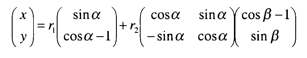
- This image data is transformed with a computer program module into a right-angled coordinate system. If the object acquisition device is rotated about a first and a second axis for data acquisition, the transformation can be carried out according to the regulation carry out.
- ⁇ and ⁇ are the angular positions of the respective axes of rotation; r 1 , r 2 are the radii of the respective axes of rotation; x, y are the coordinates of a pixel after the transformation.
- the transformation is at least partly with the help of an input lookup table of the digitizing device carried out.
- the function values could be in the input lookup table the functions sin ⁇ and sin ⁇ can be stored.
- the corresponding matrix multiplication of the transformation specification could be carried out in an FPGA module (field programmable gate array) arranged downstream of the input lookup table, in which the constants r 1 and r 2 are also stored.
- FPGA module field programmable gate array
- immersion oil is provided for the microscopic picture is, this is advantageous before the automatic assembly process - preferably automated - pipetted onto the slide.
- immersion oil For example, it could be water, glycerin or conventional immersion oil act, depending on its viscosity, however, is the maximum Upper limit of the scanning speed of the object recording device.
- the laser scanning microscope has a stationary one Illumination and detection beam on. This is a complex field correction of a microscope objective used and it can be a relative simple and inexpensive optics can be used. Especially with regard to the adjustment of the optical components, this procedure is advantageous because the The laser scan microscope can only be adjusted during production and then none further adjustment required.
- the scanning device has a rotary encoder, the output of which is connected to the control unit of the laser scanning microscope.
- This position encoder provides the momentary ones necessary for the transformation regulation Angular positions of the axes of rotation, so that a detected pixel with high accuracy can be assigned to its actual location coordinate. If for the scanning of the object receiving device provides a translational movement is in an analogous manner, the device for performing the translation movement a position sensor, the output of which is also connected to the control unit of the laser scanning microscope is connected.
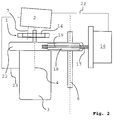
- FIG. 1 and 2 is a first embodiment of an arrangement for scanning an object receiving device 1 shown.
- the one used for data acquisition Laser scanning microscope 2 is shown schematically in FIG. 2.
- the Object receiving device 1 is rotated about a first axis 4 in an angular range 5 alternating clockwise and opposite to that Turnable clockwise.
- the object receiving device 1 can be rotated together with the rotating device 3 about a second axis 6.
- the first axis of rotation 4 is arranged parallel to the second axis of rotation 6. 4 that the two axes of rotation 4, 6 are arranged relative to the optical axis 7 of the laser scanning microscope in such a way that the resulting scan trajectories 8 of both axes run almost orthogonally to one another at their intersection points.
- 5 shows scan trajectories 8 and the resulting coordinate system.
- the scan trajectories 9 result from the alternating rotation about the first axis 4
- the scan trajectories 10 result from the alternating rotation about the second axis 6. It can further be seen from FIG.
- the radius r 1 of the first axis 4 - that is to say the distance from the first axis 4 to the optical axis 7 of the laser scanning microscope 2 - is selected to be equal to the radius r 2 of the second axis 6.
- the object receiving device 1 together with its associated rotating device 3 is moved in translation.
- the scan movement generated in this way results in the scan trajectories 8 shown in FIG which the scan trajectories 9 from the alternating rotation of the object receiving device around the first axis 4 and the scan trajectories 11 from the translational Movement along the direction 12 result.
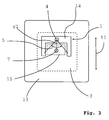
- the resulting scanning movement lies in the embodiments according to FIGS. 1 to 3 the object receiving device in a plane which is parallel to the surface of the object receiving device runs.
- the translation movement runs in the 3 also parallel to the surface of the object receiving device.
- This movement periodically runs in opposite directions 12 and is shown with a linear displacement table, shown only schematically 13 realized.
- the movable part of the linear displacement table 13 the rotating device 3, which in turn receives the object receiving device 1.
- the object receiving device 1 for optical Axis 7 of the laser scanning microscope 2 is arranged such that the normal of the Surface of the object receiving device 1 at an angle to the optical axis 7 of the laser scanning microscope 2, which is 5 degrees and not in this figure is drawn to scale.
- the excitation beam of the laser scanning microscope thus strikes at an angle of incidence of 5 degrees on the surface of the object receiving device 1 on, approx. 5% of the intensity of the excitation light is at the Surface of the object receiving device 1 at an angle of 5 degrees reflected.
- This main back reflex is thus advantageously from the detection beam path reflected out so that the fluorescent light to be detected here, which is about 3 orders of magnitude lower in intensity than the excitation light is more efficient compared to conventionally used lighting methods can be detected.
- the slide unit 14 is made of aluminum and is of this type constructed that the focus of the object receiving device 1 on the first Axis of rotation 4 lies.
- a slide 15 is not shown with the help of a Vacuum device attached to the slide unit 14, so that no additional Holding devices are arranged on the slide unit 14.
- a galvanometer is used as the rotating device 3, which at a frequency of 100 Hz is operated.
- a lever device is used as the rotating device of the second axis 6.
- the lever device has an electric motor 16, a threaded spindle 17, a rotating threaded piece 18 and a connecting element 19.
- the axis of the electric motor 16 is designed as a threaded spindle 17 and by turning the threaded spindle 17 the circulating threaded piece 18 is positioned in the direction 20.
- the electric motor 16 is around an axis 21 pivotally resiliently mounted, so that a slight imbalance of the threaded spindle 17 not on the rotating device 3 in the form of undesirable additional Movement shares is transferred.
- the circulating threaded piece 18 is with the Rotary device 3 connected via a connecting element 19.
- the connecting element 19 is designed as a leaf spring which surrounds the circulating threaded piece 18 and which is attached to the rotating part 22 at both ends thereof.
- the leaf spring points slot-shaped recesses through which the threaded spindle 17 pass can.
- Points in the area between the connecting element 19 and the rotating part 22 the part of the leaf spring from one fastening end is also a slit-shaped one Openings through which the narrowly designed part of the leaf spring of the other Fastening end can pass through. This makes transmission almost free of play the linear movement of the circulating threaded piece 18 on the rotating device 3 possible.
- the data is recorded bidirectionally with respect to the first axis 4, the measured image data present in the curvilinear coordinate system are converted into a right-angled coordinate system in accordance with a corresponding transformation specification.
- the transformation rule results from the arrangement of the axes of rotation 4, 6 or the axis of rotation 4 and the translation movement.
- ⁇ and ⁇ are the current angular positions of the object receiving device, with ⁇ parameterizing the alternating rotational movement of the first axis 4, ⁇ the alternating rotation of the second axis 6.
- r 1 and r 2 are the radii of the respective axes of rotation; x, y are the coordinates of the pixel in the right-angled coordinate system after the transformation.
- This transformation is advantageously carried out at the same time during the data acquisition with the aid of an input lookup table.
- the function values of the functions sin ⁇ , sin ⁇ , cos ⁇ , cos ( ⁇ - 1) and cos ( ⁇ - 1) for all angular positions ⁇ , ⁇ , which the object recording device can assume during the scanning process are in the input lookup Saved table.
- the matrix multiplication from the transformation specification is linked in an FPGA module (field programmable gate array) arranged downstream of the input lookup table, in which the constants r 1 and r 2 are also stored.
- the laser scanning microscope has a fixed lighting and detection beam.
- This can be used Microscope optics, especially the microscope objective, especially for a specific one Application can be selected, which reduces the cost of the overall system.
- the rotating device 3 and Electric motor 16 each have a position sensor, the output of which is connected to the control unit of the laser scanning microscope 2 is connected via the line 23.
- This Position transmitters report to the control unit of the laser scanning microscope 2 the current Actual angular position of the object receiving device - So the angles ⁇ and ⁇ - so that digitization with the help of the input lookup table the measured image data together with the simultaneous transformation can be performed in a right-angled coordinate system.
- the procedure is in the embodiment according to FIG. 3, here are the position indicators the rotating device 3 and the linear displacement table 13 with the control unit of the laser scan microscope 2 connected.
Landscapes
- Physics & Mathematics (AREA)
- Chemical & Material Sciences (AREA)
- Analytical Chemistry (AREA)
- General Physics & Mathematics (AREA)
- Optics & Photonics (AREA)
- Microscoopes, Condenser (AREA)
- Projection-Type Copiers In General (AREA)
- Facsimile Scanning Arrangements (AREA)
Abstract
Description

- Fig. 1
- in einer schematischen Darstellung ein erstes Ausführungsbeispiel einer erfindungsgemäßen Anordnung zum Scannen einer Objektaufnahmeeinrichtung,
- Fig. 2
- in einer schematischen Darstellung eine Seitenansicht der erfindungsgemäßen Anordnung zum Scannen einer Objektaufnahmeeinrichtung aus Fig. 1,
- Fig. 3
- in einer schematischen Darstellung ein alternatives Ausführungsbeispiel einer Anordnung zum Scannen einer Objektaufnahmeeinrichtung,
- Fig. 4
- die relative Lage zweier Drehachsen einer Anordnung zum Scannen einer Objektaufnahmeeinrichtung,
- Fig. 5
- in einer schematischen Darstellung die Scan-Trajektorien bzw. das resultierende Koordinatensystem einer erfindungsgemäßen Anordnung zum Scannen einer Objektaufnahmeeinrichtung,
- Fig. 6
- in einer schematischen Darstellung die Scan-Trajektorien bzw. das resultierende Koordinatensystem einer alternativen Anordnung zum Scannen einer Objektaufnahemeinrichtung.

Claims (15)
- Anordnung zum Scannen einer Objektaufnahmeeinrichtung (1) zur Datenaufnahme mit einem Laserscan-Mikroskop, vorzugsweise mit einem konfokalen Laserscan-Mikroskop (2),
dadurch gekennzeichnet, dass die Objektaufnahmeeinrichtung (1) von einer Dreheinrichtung (3) um eine erste Achse (4) alternierend drehbar ist. - Anordnung nach Anspruch 1, dadurch gekennzeichnet, dass die Objektaufnahmeeinrichtung (1) zusammen mit der Dreheinrichtung (3) um eine zweite Achse (6) drehbar ist, wobei die erste Drehachse (4) zur zweiten Drehachse (6) zumindest nahezu parallel angeordnet sein kann und wobei die beiden Drehachsen (4, 6) relativ zur optischen Achse (7) des Laserscan-Mikroskops (2) derart angeordnet sein kann, dass die resultierenden Scan-Trajektorien (8) beider Achsen (4, 6) nahezu orthogonal zueinander verlaufen.
- Anordnung nach Anspruch 1 oder 2, dadurch gekennzeichnet, dass die Objektaufnahmeeinrichtung (1) gemeinsam mit der Dreheinrichtung (3) translatorisch bewegbar ist, wobei die Translationsbewegung zumindest nahezu parallel zu der Oberfläche der Objektaufnahmeeinrichtung (1) oder entlang der optischen Achse (7) oder entlang der linearen Richtung (12) und/oder periodisch in entgegengesetzte Richtungen (12) verlaufen kann und/oder durch einen Linearverschiebetisch (13) mit entsprechenden Führungsmitteln realisierbar ist.
- Anordnung nach einem der Ansprüche 1 bis 3, dadurch gekennzeichnet, dass die resultierende Scanbewegung der Objektaufnahmeeinrichtung (1) in einer vorzugsweise zumindest nahezu parallel zu der Oberfläche der Objektaufnahmeeinrichtung (1) verlaufenden Ebene liegt.
- Anordnung nach einem der Ansprüche 1 bis 4, dadurch gekennzeichnet, dass die Objektaufnahmeeinrichtung (1) zur optischen Achse (7) des Laserscan-Mikroskops (2) derart angeordnet ist, dass die Normale der Oberfläche der Objektaufnahmeeinrichtung (1) einen Winkel zur optischen Achse (7) des Laserscan-Mikroskops (2) aufweist, der von 0 Grad verschieden ist, wobei der Winkel zwischen der Normale der Oberfläche der Objektaufnahmeeinrichtung (1) und der optischen Achse (7) des Laserscan-Mikroskops (2) durch eine verkippte Anordnung mindestens einer Drehachse (4) relativ zur optischen Achse erzielt werden kann und vorzugsweise größer als 0 und kleiner als 10 Grad ist.
- Anordnung nach einem der Ansprüche 1 bis 5, dadurch gekennzeichnet, dass die Objektaufnahmeeinrichtung (1) einen Objektträger (15) und eine Objektträgereinheit (14) aufweist, wobei die Objektaufnahmeeinrichtung (1) vorzugsweise automatisch mit Objektträger (15) bestückbar ist und aus Material geringer Dichte/Masse, vorzugsweise aus Plastik oder Aluminium und der Objektträger (15) zumindest teilweise aus Material geringer Dichte/Masse, vorzugsweise aus Plastik, bestehen kann.
- Anordnung nach Anspruch 6, dadurch gekennzeichnet, dass der Objektträger (15) mit mindestens einer Klemmvorrichtung an der Objektträgereinheit (14) oder mit Hilfe einer Unterdruck- bzw. Vakuumeinrichtung an der Objektträgereinheit (14) oder aufgrund magnetischer oder elektromagnetischer Wechselwirkung an der Objektträgereinheit (14) befestigbar ist.
- Anordnung nach einem der Ansprüche 1 bis 7, dadurch gekennzeichnet, dass als Dreheinrichtung (3) ein Galvanometer verwendet wird, wobei das Galvanometer mit einer Frequenz betrieben wird, die in einem Bereich von 10 bis 1000 Hz liegen kann und als Dreheinrichtung (3) vorzugsweise ein resonantes Galvanometer verwendbar ist.
- Anordnung nach einem der Ansprüche 1 bis 8, dadurch gekennzeichnet, dass als Dreheinrichtung (3) für die zweite Achse (6) ein Galvanometer vorgesehen ist.
- Anordnung nach einem der Ansprüche 1 bis 9, dadurch gekennzeichnet, dass als Dreheinrichtung für die zweite Achse (6) eine Hebeleinrichtung vorgesehen ist, wobei die Hebeleinrichtung einen Elektromotor (16), eine Gewindespindel (17), ein Umlaufgewindestück (18) und ein Verbindungselement (19) umfassen kann und wobei die Gewindespindel (17) vorzugsweise der Achse des Elektromotors (16) zugeordnet ist, wobei das Umlaufgewindestück (18) durch Drehen der Gewindespindel (17) in der Richtung der Achse der Gewindespindel (17) positionierbar sein kann und wobei das Verbindungselement (19) vorzugsweise das Umlaufgewindestück (18) und die Dreheinrichtung (3) verbindet und als Blattfeder ausgeführt sein kann, wobei der Elektromotor (16) um eine Achse (21) schwenkbar federnd gelagert sein kann.
- Anordnung nach einem der Ansprüche 1 bis 10, dadurch gekennzeichnet, dass die Datenaufnahme bezüglich der schnellen Drehachse unidirektional oder bidirektional erfolgt.
- Anordnung nach einem der Ansprüche 1 bis 11, dadurch gekennzeichnet, dass die gemessenen, im krummlinigen Koordinatensystem vorliegenden Bilddaten in ein rechtwinkliges Koordinatensystem transformiert werden, wobei die Transformation gemäß der Vorschriftdurchgeführt werden kann, wobei α, β die Winkelstellung der jeweiligen Drehachsen, r1, r2, die Radien der jeweiligen Drehachsen und x, y die Koordinaten eines Bildpunktes nach der Transformation sind und wobei die Transformation zumindest teilweise mit Hilfe einer Eingangs-Lookup-Tabelle durchgeführt werden kann.
- Anordnung nach einem der Ansprüche 1 bis 12, dadurch gekennzeichnet, dass bei Verwendung von Immersionsöl dieses vor dem automatischen Bestückungsvorgang vorzugsweise automatisch auf den Objektträger pipettiert wird.
- Anordnung nach einem der Ansprüche 1 bis 13, dadurch gekennzeichnet, dass das Laserscan-Mikroskop (2) einen ortsfesten Beleuchtungs- und Detektionsstrahl aufweist.
- Anordnung nach einem der Ansprüche 1 bis 14, dadurch gekennzeichnet, dass die Dreheinrichtung (3) einen Positionsgeber aufweist, dessen Ausgang mit der Steuerungseinheit des Laserscan-Mikroskops (2) verbunden ist und/oder dass die Einrichtung zur Durchführung der Translationsbewegung einen Positionsgeber aufweist, dessen Ausgang mit der Steuerungseinheit des Laserscan-Mikroskops (2) verbunden ist.
Applications Claiming Priority (2)
| Application Number | Priority Date | Filing Date | Title |
|---|---|---|---|
| DE19956438 | 1999-11-24 | ||
| DE19956438A DE19956438A1 (de) | 1999-11-24 | 1999-11-24 | Anordnung zum Scannen einer Objektaufnahmeeinrichtung |
Publications (2)
| Publication Number | Publication Date |
|---|---|
| EP1107037A2 true EP1107037A2 (de) | 2001-06-13 |
| EP1107037A3 EP1107037A3 (de) | 2003-10-01 |
Family
ID=7930118
Family Applications (1)
| Application Number | Title | Priority Date | Filing Date |
|---|---|---|---|
| EP00125470A Withdrawn EP1107037A3 (de) | 1999-11-24 | 2000-11-21 | Anordnung zum Scannen einer Objektaufnahmeeinrichtung |
Country Status (4)
| Country | Link |
|---|---|
| US (1) | US6576901B1 (de) |
| EP (1) | EP1107037A3 (de) |
| JP (1) | JP2001249279A (de) |
| DE (1) | DE19956438A1 (de) |
Cited By (1)
| Publication number | Priority date | Publication date | Assignee | Title |
|---|---|---|---|---|
| EP2472302A3 (de) * | 2010-12-29 | 2012-08-29 | Leica Microsystems CMS GmbH | Verfahren zur Korrektur von Bildverzeichnungen bei einem konfokalen Scan-Mikroskop |
Families Citing this family (1)
| Publication number | Priority date | Publication date | Assignee | Title |
|---|---|---|---|---|
| US8741232B2 (en) | 2012-09-05 | 2014-06-03 | Faxitron Bioptics, Llc | Specimen imaging device and methods for use thereof |
Family Cites Families (6)
| Publication number | Priority date | Publication date | Assignee | Title |
|---|---|---|---|---|
| US4029949A (en) * | 1975-07-08 | 1977-06-14 | The Charles Stark Draper Laboratory, Inc. | Servo-controlled microscope stage |
| US5029023A (en) * | 1989-09-29 | 1991-07-02 | Regents Of The University Of California | Laser-amplified motion detector and method |
| US5578832A (en) * | 1994-09-02 | 1996-11-26 | Affymetrix, Inc. | Method and apparatus for imaging a sample on a device |
| WO1997004347A1 (en) * | 1995-07-19 | 1997-02-06 | Morphometrix Technologies Inc. | Automated scanning of microscope slides |
| DE19629725C2 (de) * | 1996-07-23 | 1998-09-17 | Europ Lab Molekularbiolog | Doppelobjektiv-System für ein Mikroskop, insbesondere Rastermikroskop |
| DE19714221A1 (de) * | 1997-04-07 | 1998-10-08 | Zeiss Carl Fa | Konfokales Mikroskop mit einem motorischen Scanningtisch |
-
1999
- 1999-11-24 DE DE19956438A patent/DE19956438A1/de not_active Withdrawn
-
2000
- 2000-11-15 US US09/713,071 patent/US6576901B1/en not_active Expired - Fee Related
- 2000-11-21 EP EP00125470A patent/EP1107037A3/de not_active Withdrawn
- 2000-11-22 JP JP2000356332A patent/JP2001249279A/ja active Pending
Cited By (4)
| Publication number | Priority date | Publication date | Assignee | Title |
|---|---|---|---|---|
| EP2472302A3 (de) * | 2010-12-29 | 2012-08-29 | Leica Microsystems CMS GmbH | Verfahren zur Korrektur von Bildverzeichnungen bei einem konfokalen Scan-Mikroskop |
| CN102654638A (zh) * | 2010-12-29 | 2012-09-05 | 徕卡显微系统复合显微镜有限公司 | 用于校正共聚焦扫描显微镜中的图像失真的方法 |
| US9372329B2 (en) | 2010-12-29 | 2016-06-21 | Leica Microsystems Cms Gmbh | Method for correcting image distortions in a confocal scanning microscope |
| CN102654638B (zh) * | 2010-12-29 | 2017-04-12 | 徕卡显微系统复合显微镜有限公司 | 用于校正共聚焦扫描显微镜中的图像失真的方法 |
Also Published As
| Publication number | Publication date |
|---|---|
| EP1107037A3 (de) | 2003-10-01 |
| US6576901B1 (en) | 2003-06-10 |
| DE19956438A1 (de) | 2001-05-31 |
| JP2001249279A (ja) | 2001-09-14 |
Similar Documents
| Publication | Publication Date | Title |
|---|---|---|
| DE19544178B4 (de) | Vorrichtung zum scannenden Digitalisieren von Bildvorlagen sowie Verfahren zu deren Betrieb | |
| DE19544299C2 (de) | Verfahren und Vorrichtung zum Vermessen von Strukturen | |
| DE19721688B4 (de) | Oberflächenerfassungseinrichtung und Verfahren zur Oberflächenerfassung | |
| EP1610088A1 (de) | Vorrichtung zum optischen Vermessen eines Objektes | |
| DE112006001713B4 (de) | Winkelmessvorrichtung und -verfahren | |
| DE102015221599A1 (de) | Werkzeugmaschine | |
| DE202019105838U1 (de) | Anordnung mit einem Koordinatenmessgerät oder Mikroskop | |
| EP4227636B1 (de) | Bestimmung von tiefenwerten eines oberflächenbereichs eines werkstücks | |
| EP1640688A1 (de) | Verfahren und Vorrichtung zur 3-dimensionalen Vermessung der Oberfläche eines Gegenstands | |
| DE69225847T2 (de) | Röntgenanalyseapparat | |
| DE2640793A1 (de) | Schallmikroskop | |
| DE102007036850B4 (de) | Verfahren zur Korrektur von Nichtlinearitäten der Interferometer einer Koordinaten-Messmaschine | |
| DE3878021T2 (de) | Synchrone optische abtastvorrichtung. | |
| DE102005047200B4 (de) | Verfahren zur Korrektur einer Steuerung eines optischen Scanners in einer Vorrichtung zur scannenden Abbildung einer Probe und Vorrichtung zur Erzeugung eines Bildes einer Probe durch Abscannen der Probe | |
| EP1113304B1 (de) | Vorrichtung zum optischen Abtasten mehrerer Objekte | |
| DE4113279C2 (de) | Konfokales optisches Rastermikroskop | |
| DE102024109226A1 (de) | Verfahren zur Erfassung eines zusammengefügten Mikroskopbildes, Mikroskopsystem und Computerprogrammprodukt | |
| DE602004003347T2 (de) | Optische röntgenstrahlungsvorrichtung mit verstellbarer konvergenz | |
| DE102005047218B4 (de) | Verfahren zur Steuerung eines optischen Scanners, optischer Scanner und Laser-Scanning-Mikroskop | |
| DE69117215T2 (de) | Rastertunnelmikroskop | |
| DE10317679B4 (de) | Röntgen-optische Vorrichtung mit Wobbel-Einrichtung | |
| DE3616283C2 (de) | ||
| EP0135673A2 (de) | Verfahren und Vorrichtung zur Festlegung einer Koordinate auf einer Oberfläche eines Festkörpers | |
| DE19829776C1 (de) | Scannerkopf zur Abtastung von Vorlagen | |
| EP1107037A2 (de) | Anordnung zum Scannen einer Objektaufnahmeeinrichtung |
Legal Events
| Date | Code | Title | Description |
|---|---|---|---|
| PUAI | Public reference made under article 153(3) epc to a published international application that has entered the european phase |
Free format text: ORIGINAL CODE: 0009012 |
|
| AK | Designated contracting states |
Kind code of ref document: A2 Designated state(s): AT BE CH CY DE DK ES FI FR GB GR IE IT LI LU MC NL PT SE TR |
|
| AX | Request for extension of the european patent |
Free format text: AL;LT;LV;MK;RO;SI |
|
| PUAL | Search report despatched |
Free format text: ORIGINAL CODE: 0009013 |
|
| AK | Designated contracting states |
Kind code of ref document: A3 Designated state(s): AT BE CH CY DE DK ES FI FR GB GR IE IT LI LU MC NL PT SE TR |
|
| AX | Request for extension of the european patent |
Extension state: AL LT LV MK RO SI |
|
| 17P | Request for examination filed |
Effective date: 20031030 |
|
| AKX | Designation fees paid |
Designated state(s): CH DE FR GB LI |
|
| RAP1 | Party data changed (applicant data changed or rights of an application transferred) |
Owner name: LEICA MICROSYSTEMS CMS GMBH |
|
| GRAP | Despatch of communication of intention to grant a patent |
Free format text: ORIGINAL CODE: EPIDOSNIGR1 |
|
| STAA | Information on the status of an ep patent application or granted ep patent |
Free format text: STATUS: THE APPLICATION IS DEEMED TO BE WITHDRAWN |
|
| 18D | Application deemed to be withdrawn |
Effective date: 20090918 |