EP1108273B1 - Explosionsgeschützte steckverbindungsanordnung - Google Patents
Explosionsgeschützte steckverbindungsanordnung Download PDFInfo
- Publication number
- EP1108273B1 EP1108273B1 EP99953537A EP99953537A EP1108273B1 EP 1108273 B1 EP1108273 B1 EP 1108273B1 EP 99953537 A EP99953537 A EP 99953537A EP 99953537 A EP99953537 A EP 99953537A EP 1108273 B1 EP1108273 B1 EP 1108273B1
- Authority
- EP
- European Patent Office
- Prior art keywords
- plug connector
- arrangement according
- plug
- connector arrangement
- switch means
- Prior art date
- Legal status (The legal status is an assumption and is not a legal conclusion. Google has not performed a legal analysis and makes no representation as to the accuracy of the status listed.)
- Expired - Lifetime
Links
Images


Classifications
-
- H—ELECTRICITY
- H01—ELECTRIC ELEMENTS
- H01R—ELECTRICALLY-CONDUCTIVE CONNECTIONS; STRUCTURAL ASSOCIATIONS OF A PLURALITY OF MUTUALLY-INSULATED ELECTRICAL CONNECTING ELEMENTS; COUPLING DEVICES; CURRENT COLLECTORS
- H01R13/00—Details of coupling devices of the kinds covered by groups H01R12/70 or H01R24/00 - H01R33/00
- H01R13/46—Bases; Cases
- H01R13/52—Dustproof, splashproof, drip-proof, waterproof, or flameproof cases
- H01R13/527—Flameproof cases
-
- H—ELECTRICITY
- H01—ELECTRIC ELEMENTS
- H01R—ELECTRICALLY-CONDUCTIVE CONNECTIONS; STRUCTURAL ASSOCIATIONS OF A PLURALITY OF MUTUALLY-INSULATED ELECTRICAL CONNECTING ELEMENTS; COUPLING DEVICES; CURRENT COLLECTORS
- H01R13/00—Details of coupling devices of the kinds covered by groups H01R12/70 or H01R24/00 - H01R33/00
- H01R13/66—Structural association with built-in electrical component
- H01R13/70—Structural association with built-in electrical component with built-in switch
- H01R13/703—Structural association with built-in electrical component with built-in switch operated by engagement or disengagement of coupling parts, e.g. dual-continuity coupling part
- H01R13/7036—Structural association with built-in electrical component with built-in switch operated by engagement or disengagement of coupling parts, e.g. dual-continuity coupling part the switch being in series with coupling part, e.g. dead coupling, explosion proof coupling
- H01R13/7038—Structural association with built-in electrical component with built-in switch operated by engagement or disengagement of coupling parts, e.g. dual-continuity coupling part the switch being in series with coupling part, e.g. dead coupling, explosion proof coupling making use of a remote controlled switch, e.g. relais, solid state switch activated by the engagement of the coupling parts
-
- H—ELECTRICITY
- H02—GENERATION; CONVERSION OR DISTRIBUTION OF ELECTRIC POWER
- H02H—EMERGENCY PROTECTIVE CIRCUIT ARRANGEMENTS
- H02H9/00—Emergency protective circuit arrangements for limiting excess current or voltage without disconnection
- H02H9/001—Emergency protective circuit arrangements for limiting excess current or voltage without disconnection limiting speed of change of electric quantities, e.g. soft switching on or off
- H02H9/004—Emergency protective circuit arrangements for limiting excess current or voltage without disconnection limiting speed of change of electric quantities, e.g. soft switching on or off in connection with live-insertion of plug-in units
-
- H—ELECTRICITY
- H02—GENERATION; CONVERSION OR DISTRIBUTION OF ELECTRIC POWER
- H02H—EMERGENCY PROTECTIVE CIRCUIT ARRANGEMENTS
- H02H9/00—Emergency protective circuit arrangements for limiting excess current or voltage without disconnection
- H02H9/008—Intrinsically safe circuits
-
- H—ELECTRICITY
- H03—ELECTRONIC CIRCUITRY
- H03K—PULSE TECHNIQUE
- H03K17/00—Electronic switching or gating, i.e. not by contact-making and –breaking
- H03K17/08—Modifications for protecting switching circuit against overcurrent or overvoltage
- H03K17/082—Modifications for protecting switching circuit against overcurrent or overvoltage by feedback from the output to the control circuit
- H03K17/0826—Modifications for protecting switching circuit against overcurrent or overvoltage by feedback from the output to the control circuit in bipolar transistor switches
-
- H—ELECTRICITY
- H02—GENERATION; CONVERSION OR DISTRIBUTION OF ELECTRIC POWER
- H02H—EMERGENCY PROTECTIVE CIRCUIT ARRANGEMENTS
- H02H3/00—Emergency protective circuit arrangements for automatic disconnection directly responsive to an undesired change from normal electric working condition with or without subsequent reconnection ; integrated protection
- H02H3/08—Emergency protective circuit arrangements for automatic disconnection directly responsive to an undesired change from normal electric working condition with or without subsequent reconnection ; integrated protection responsive to excess current
- H02H3/087—Emergency protective circuit arrangements for automatic disconnection directly responsive to an undesired change from normal electric working condition with or without subsequent reconnection ; integrated protection responsive to excess current for DC applications
-
- H—ELECTRICITY
- H02—GENERATION; CONVERSION OR DISTRIBUTION OF ELECTRIC POWER
- H02H—EMERGENCY PROTECTIVE CIRCUIT ARRANGEMENTS
- H02H5/00—Emergency protective circuit arrangements for automatic disconnection directly responsive to an undesired change from normal non-electric working conditions with or without subsequent reconnection
- H02H5/04—Emergency protective circuit arrangements for automatic disconnection directly responsive to an undesired change from normal non-electric working conditions with or without subsequent reconnection responsive to abnormal temperature
- H02H5/042—Emergency protective circuit arrangements for automatic disconnection directly responsive to an undesired change from normal non-electric working conditions with or without subsequent reconnection responsive to abnormal temperature using temperature dependent resistors
-
- H—ELECTRICITY
- H03—ELECTRONIC CIRCUITRY
- H03K—PULSE TECHNIQUE
- H03K17/00—Electronic switching or gating, i.e. not by contact-making and –breaking
- H03K17/08—Modifications for protecting switching circuit against overcurrent or overvoltage
- H03K2017/0806—Modifications for protecting switching circuit against overcurrent or overvoltage against excessive temperature
Definitions
- EP 0 261 307 describes an explosion-proof device Module housing known, that in hazardous areas can be arranged and is provided with other identical module housings together in one frame to be used.
- For the electrical connection of the Module housing with one another or with one or more Power supplies are two types of on each module housing Connector groups provided.
- One group is made of pins of a commercially available Power strip formed with a likewise commercially available socket strip in the frame electrical and interact mechanically. Be through these contact points all intrinsically safe circuits.
- Intrinsically safe circuits in terms of explosion protection are circuits in which the voltage against one other current-carrying conductor below a predetermined one Voltage limit is that of the expected ignitable gas mixtures is dependent. In addition, must inevitably ensure that on intrinsically safe Circuits the current below a predetermined limit remains, which also depends on the ignitability of the expected Mixture is dependent.
- the special connectors in turn consist of a Plug strip on the module housing and a socket strip in the frame.
- they are designed so that the connector pin enclosed in the socket strip by a contact space is the conditions for when the plug is inserted fulfills the type of protection "flameproof enclosure".
- the gap between the hole in the insulating body for the socket and an insulating jacket of the Plug pin meet the conditions of the "Ex gap”. Since these tolerances are relatively narrow, the result for Connector means of the non-intrinsically safe circuits considerable manufacturing and construction costs and a not inconsiderable Space requirements.
- DE-A-34 46 396 describes an explosion-proof electrical connector system in which the consumer side with plug pins and the feeding side with sockets is provided. It flows through these sockets and plugs in the case of interconnected connection systems, the load current.
- the load current In addition to these plugs and sockets for the load current are two more connector pins on the consumer side present that are galvanically connected to each other and something are shorter than the connector pins for the Load current.
- These shortened connector pins work with the corresponding ones Mating sockets of the counterpart, which in the control circuit of a relay or contactor.
- the load current flows in via the switching contacts of the relay the load current sockets.
- the contactor When the plug is inserted, the contactor is switched on and it can load current through the main power connector pins flow. When pulling out the plug unit the control circuit is first disconnected, whereby the main power connector pins become dead so they finally get along without the danger of an opening spark let the bushes pull out.
- a controllable switch device for this purpose has an input and an output.
- This switch device is on the input side to the at least one connector pin or on the output side to the at least one socket electrically connected.
- the switch device knows two operating states, namely a low impedance Operating state and a high-resistance operating state, each measured between entrance and exit.
- the switch device is a control device assigned, which works with a control signal that from the other connector part comes in the way that the control device the switching device brings it into the low-resistance state only when the at least one connector pin with the at least one Socket a reliable electrically conductive connection forms, while conversely the switching device already then brought into the high impedance state, still before disconnecting the electrically conductive connection between the plug pin and the socket becomes.
- the switch device When used in busbar systems, it is advantageous to if the switch device is not in the busbar, but is arranged on the side of the consumer.
- Housing on the side of the consumer also automatically disconnects the connector pins, which is required if on the consumer side Capacitors are included, which may to increase at the connector pins for a long time Lead voltages against other connector pins. In this Trap would be without the switch device by the Placing discharge sparks on an electrically conductive surface can be generated.
- Plug pins individually or as a whole from a protective collar surround.
- one or more protective collars are provided.
- the protective collar or collars as mechanical Protection for those who can be quite delicate Plug pins serve when the collar has a depth which is greater than the length of the connector pin or pins equivalent.
- the space requirement for the switch device becomes extreme small when used as a purely electronic switching device is executed. It is expediently designed to be redundant, if one of the important semiconductors fails the circuit is definitely interrupted correctly.
- the control signal can be in the control current for the Switch device exist. It then comes from the connector part, that is not assigned to the switch device is when the control current at least once over the Connection between the two connector parts flows.
- control circuit is in any case an intrinsically safe circle that no special protective measures required.
- the desired temporal relation regarding the Contacting can be done easily through the spatial Arrangement of the sockets or the length of the connector pins Taxes.
- By shortened connector pins for the Control circuit will be the desired lag when plugging together or the necessary advance when separating reached.
- An overload protection device is provided to protect the switch devices. There may be additional ones thermal sensors are present that lead to a Switch off, the switch device should not be permitted Reach temperatures. It is also conceivable that Detect current and the switch devices forced in the OFF state, the current should be a predetermined Exceed limit, which is significantly lower is the permissible limit value of the components.
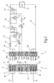
- Fig. 1 shows a schematic diagram of an explosion-proof Connector arrangement 1.
- To the connector arrangement 1 includes two connectors 2 and 3 and a switch device 4, which is a control device 5 is assigned.
- the connector 2 consists of a cuboid Holder or base body 6, which is made of an insulating material is.
- the base body 6 is from a flat front 7, a flat back 8 and side surfaces 9 limited.
- Each bushing seat 11 consists of one at the front 7 adjacent section 13 and a section 14 together.
- the section 13 opens out at the front 7 an insertion opening 15, while the section 14 at one Opening 15 to the back 8 is open.
- the section 14 has a smaller cross section than the section 13, so that the two sections 13 and 14 on a shoulder 16 merge.
- the shoulders 16 of the socket seats 11d, 11e and 11f is towards the rear 8 offset compared to the shoulders 16 of the socket seats 11a, 11b, 11c and 11g, 11h and 11i. Sit this way the sockets 12 located therein somewhat deeper to the front 7 when the sockets in the Bush seats 11a ... 11c and 11g ... 11i.
- Each socket 12 consists of a metallic tubular section 17 which at its rear into a Solder tail passes through section 14 of the concerned Socket seat 11 from the rear 8 of the carrier 6 protrudes.
- the connector part 3 also consists of a cuboid base body 21 with a front side 22, a rear side 23 and side surfaces 24.
- the base body 21 In the base body 21 are seats aligned with the socket seats 11a ... 11i 24a ... 24i included.
- the seats 24a ... 24i have a similar one Shape like the socket seats 11 and extend from the front 22 to the back 23. Since they have a similar shape will have another detailed explanation waived.
- the connector pins 26c ... 26e measured from the Front 22, a slightly shorter length than the connector pins 26a ... 26c or 26g ... 26i.
- the Insert the plug pins 26 into the associated sockets 12 first the connector pins 26a ... 26c and the Connector pins 26g ... 26i with the associated sockets 12 make an electrical contact before making an electrical conductive connection between the connector pins 26c ... 26f with the associated sockets 12 in the socket seats 11d ... 11f comes about, i.e. contacting the connector pins 26d ... 26f lags behind when plugged together.
- This Measure alone would suffice.
- a lowering the sockets 12 in the socket seats 11d..11f is not absolutely necessary.
- the switch device 4 is on with its input 30 the three electrically connected in parallel to each other Connector pins 26a ... 26c connected. It contains the input side a fuse 31 with which a current sensor resistor 32 is in series. To the current sensor resistor 32, as shown, closes a PNP transistor 33 whose emitter is connected to resistor 32 while its collector is connected to another current sensor resistor 34 is switched on. With this in turn lies second PNP transistor 35 in series, with its emitter is connected to the current sensor resistor 34. The collector of the transistor 35 leads via a connecting line 36 to a load or a consumer 37.
- The is parallel to the current sensor resistor 32 Base-emitter path of a PNP transistor 38, specifically in such a way that its emitter at the junction between the Fuse 31 and the current sensor resistor 32 connected while the base is connected to the emitter of transistor 33 connected is.
- the collector of transistor 38 is present the base of transistor 33 and also to the base-emitter path of the transistor 33, a bleeder resistor 39 connected in parallel.
- Another similar configuration is to the transistor 35 connected, and is parallel to that Current sensor resistor 34 the base-emitter path of a PNP transistor 41, whose emitter with the collector of Transistor 33 is connected while its base is connected to the Emitter of transistor 35 is turned on.
- the collector of transistor 41 leads to the base of transistor 35, its base emitter path also over another Discharge resistor 42 is shunted.
- a resistor 43 leads to it series-connected PTC resistor 44, the thermally with the housing of transistor 33 is coupled.
- the other The end of the PTC resistor 44 is connected to the plug pin 26d electrically connected.
- the plug pin 26e is connected to a PTC resistor 45 connected from where the electrical connection via a Resistor 46 continues to the collector of transistor 41 or the base of transistor 35 leads.
- the PTC resistor 35 is thermally fixed to the housing of transistor 35 coupled.
- the connector pins 26f ... 26i are on their solder lugs 28 connected to each other and are connected to a circuit ground 47, on which the load 37 is also switched on with its cold end is.
- the sockets in the socket seats 11d ... 11f 12 are short-circuited to one another via a line 49, however, from all other sockets 12 galvanically Cut. After all, they are also in the socket seats 11g ... 11i existing sockets 12 together galvanically connected and for example via a line 51 with the negative pole of the aforementioned power source shown connected, the negative pole, for example, the switching ground represents.
- the contact pins 26a ... 26c with the associated sockets 12 in the connector 2 and at the same time the contact pins 26g ... 26i with the corresponding sockets 12 a galvanic connection produce. This creates a galvanic connection between the live line 48 and the Input 30 of the switch device 4, formed by the Fuse 31 and between the line 51 and the Line 47.
- the contact pins 26d ... 26f are initially by the associated sockets 12 can still be separated. This means, that neither transistor 33 nor transistor 35 is on its base gets a corresponding negative bias. Rather, the respective basis is about the shunt resistance 39 or 42 connected to the associated emitter, so that both transistors 33 and 35 are blocked.
- the Output line 36 will consequently be de-energized and it can no current flow through consumer 37; the connection about the consumer 37 i.e. the main circuit is broken.
- a base current for the Transistor 35 by one from the base of transistor 35 via the resistor 46, the PTC resistor 45, the connector pin 26e, the line 49 to the connector pin 26f and in turn flows to the circuit ground 47.
- the main circuit is now released.
- the Consumer or the load 37 can now take electricity.
- transistor 33 or transistor 35 is switched off or both transistors are used at the same time switched off when first the plug pin 26f from the associated socket 12 is released. This will cause the Output 36 the voltage for consumer 37 is switched off, i.e. it becomes the connector between the two Connectors 2 and 3 de-energized, although still one galvanic connection for the main circuit exists.
- Fig. 2 shows a circuit arrangement which is different from differs from the embodiment of FIG. 1 in that that the contact sockets 12, which with the connector pins 26d and 26e cooperate, via a line 52 directly with the Lead 51 are connected.
- the connector pin 26f can be saved, although it is still illustrated in FIG. 2 is.
- the switch device 4 differs from the previous two essentially by location the switch device 4. It is on the side the power supply between the power supply and the Connector while connector 3 is galvanic is connected directly to the consumer 37. As a result, the emitter of the transistor 35 is connected to the sockets 12 for the connector pins 26a ... 26c.
- the two PTC resistors 44 and 45 are corresponding with the sockets 12 for the Connector pins 26d and 26e connected while on the side of the connector 3, the connector pins 26d ... 26f via a Line 52 directly with line 47 and thus the connector pins 26g ... 26i are connected.
- a protective collar 55 is integrally formed on the base body 21, which has a greater axial extent than the connector pins 26. When inserted, it overlaps the Base body 6 of the connector 2. So that the Inserting bare sections into the connector the connector pins 26 protected.
- a connector arrangement has two connector strips on, in the mated condition of the Electricity flows from a power source to a consumer. Between a connector strip and the power source or the consumer sits a switch device whose Control signal also via the two connector strips leads. The contacts for the main circuits hurry while the contacts for the control current lag so that the main circuits are already closed before the Control circuit is turned on. This will create a Current flow in the main circuits when plugging or unplugging of main circuit contacts prevented.
Landscapes
- Details Of Connecting Devices For Male And Female Coupling (AREA)
- Connector Housings Or Holding Contact Members (AREA)
Description
Claims (23)
- Explosionsgeschützte Steckverbindungsanordnung (1) zwischen einer Stromversorgung und einem Verbraucher (37),
mit einem ersten Steckverbindungsteil (2), das wenigstens eine Steckbuchse (12) aufweist, die in einem Halterteil (6) angeordnet ist, das aus einem Isolierstoff besteht und deren Einstecköffnung (15) durch eine zugeordnete Zugangsöffnung in dem Halterteil (6) zugänglich ist,
mit einem zweiten Steckverbindungsteil (3), das wenigstens einen Steckerstift (26) aufweist, der in einem Halterteil (21) angeordnet ist, das aus einem Isolierstoff besteht,
mit wenigstens einer steuerbaren Schaltereinrichtung (4), die einen Eingang (30) und einen Ausgang (36) aufweist, die eingangsseitig an den wenigsten einen Steckerstift (26) oder ausgangsseitig an die wenigstens eine Steckbuchse (12) elektrisch angeschlossen ist und die zwei Schaltzustände aufweist, wobei in dem einen Schaltzustand die Schaltereinrichtung (4) zwischen ihrem Eingang (30) und ihrem Ausgang (36) hochohmig und in dem anderen Schaltzustand die Schaltereinrichtung (4) zwischen ihrem Eingang (30) und ihrem Ausgang (36) niederohmig ist,
mit einer einen Steuerstromkreis enthaltenden Steuereinrichtung (5), deren Steuersignal aus demjenigen Steckverbindungsteil (2,3) kommt, das der Schaltereinrichtung (4) nicht unmittelbar zugeordnet ist, wobei die Steuereinrichtung (5) derart gestaltet ist,und gekennzeichnet durchdass sie die Schaltereinrichtung (4) erst dann in den niederohmigen Zustand bringt, wenn der wenigstens eine Steckerstift (26) mit der wenigstens einen Steckbuchse (12) eine elektrisch leitende Verbindung bildet, unddass sie die Schaltereinrichtung (4) bereits dann in den hochohmigen Zustand bringt, wenn beim Trennen der wenigstens eine Steckerstift (26) mit der wenigstens einen Steckbuchse (12) noch eine elektrisch leitende Verbindung bildet,
eine Überlastungsschutzeinrichtung (44,45;38,41), die zum Schutz der Schaltereinrichtung (4) vorgesehen ist. - Steckverbindungsanordnung nach Anspruch 1, dadurch gekennzeichnet, dass die Schaltereinrichtung (4) auf der Seite der Steckverbindungsanordnung (1) vorgesehen ist, die dem Verbraucher (37) entspricht.
- Steckverbindungsanordnung nach Anspruch 1, dadurch gekennzeichnet, dass das erste Steckverbindungsteil (2) und das zweite Steckverbindungsteil (3) aufeinander abgestimmt sind.
- Steckverbindungsanordnung nach Anspruch 1, dadurch gekennzeichnet, dass die wenigstens eine Steckbuchse (12) in dem ersten Steckverbindungsteil (2) berührungssicher angeordnet ist.
- Steckverbindungsanordnung nach Anspruch 1, dadurch gekennzeichnet, dass das zweite Steckverbindungsteil (3) einen Kragen (55) aufweist, der den wenigstens einen Steckerstift (26) oder mehrere Steckerstifte (26) gemeinsam umgibt.
- Steckverbindungsanordnung nach Anspruch 5, dadurch gekennzeichnet, dass der Kragen (55) eine Tiefe aufweist, die größer ist als die Länge des wenigstens einen Steckerstifts (26).
- Steckverbindungsanordnung nach Anspruch 5, dadurch gekennzeichnet, dass der Kragen (55) an dem Halterteil (21) aus Isolierstoff einstückig angeformt ist.
- Steckverbindungsanordnung nach Anspruch 1, dadurch gekennzeichnet, dass sie je elektrischer Verbindung zwischen der Stromversorgung und dem Verbraucher (37) wenigstens eine Steckbuchse (12) und einen zugehörigen Steckerstift (26) aufweist, wobei die Kombination die Schutzbedingungen "erhöhte Sicherheit" oder "nicht störanfällige Verbindung" gemäß der Zündschutzart "Eigensicherheit" erfüllt.
- Steckverbindungsanordnung nach Anspruch 1, dadurch gekennzeichnet, dass sie je elektrischer Verbindung zwischen der Stromversorgung und dem Verbraucher (37) mehrere Steckbuchsen (12) und zugehörige Steckerstifte (26) aufweist, die elektrisch parallelgeschaltet sind, wobei keine der Kombinationen für sich alleine die Schutzbedingungen "erhöhte Sicherheit" oder "nicht störanfällige Verbindung" gemäß der Zündschutzart "Eigensicherheit" erfüllt.
- Steckverbindungsanordnung nach Anspruch 1, dadurch gekennzeichnet, dass die Schaltereinrichtung (4) eine elektronische Schaltereinrichtung ist.
- Steckverbindungsanordnung nach Anspruch 1, dadurch gekennzeichnet, dass die Schaltereinrichtung (4) redundant aufgebaut ist.
- Steckverbindungsanordnung nach Anspruch 1, dadurch gekennzeichnet, dass die Schaltereinrichtung (4) wenigstens einen gesteuerten Halbleiter (33,35) mit Steuereingang als Schalter enthält.
- Steckverbindungsanordnung nach Anspruch 1, dadurch gekennzeichnet, dass die Schaltereinrichtung (4) wenigstens zwei gesteuerten Halbleiter (33,35) mit Steuereingang als Schalter enthält.
- Steckverbindungsanordnung nach Anspruch 1, dadurch gekennzeichnet, dass dem jeweiligen Steuereingang ein Steuerstromkreis zugeordnet ist, der zu der Steuereinrichtung (5) gehört, und dass der Steuerstromkreis (5) über die beiden Steckverbindungsteile (2,3) geschleift ist.
- Steckverbindungsanordnung nach Anspruch 1, dadurch gekennzeichnet, dass der Steuerstromkreis (5) von dem zweiten Steckverbindungsteil (3) zu dem ersten Steckverbindungsteil (2) führt.
- Steckverbindungsanordnung nach Anspruch 15, dadurch gekennzeichnet, dass der Steuerstromkreis (5) von dem ersten Steckverbindungsteil (2) zu dem zweiten Steckverbindungsteil (3) zurückgeschleift ist.
- Steckverbindungsanordnung nach Anspruch 1, dadurch gekennzeichnet, dass die Steuereinrichtung (5) wenigstens eine Steuersteckbuchse (12) und wenigstens einen Steuersteckerstift (26d..f) für den Steuerstromkreis (5) aufweist und dass die Steuersteckbuchse (12) in dem ersten Steckverbindungsteil (2) und der Steuersteckerstift (26d..26f) in dem zweiten Steckverbindungsteil (3) enthalten ist.
- Steckverbindungsanordnung nach Anspruch 17, dadurch gekennzeichnet, dass der Steuersteckerstift (26d..f) und die Steuersteckbuchse (12) derart in dem jeweiligen Halterteil (6,21) untergebracht sind, dass sie erst dann eine elektrische Verbindung herstellen, wenn die elektrische Verbindung über die wenigstens eine Steckbuchse (12) und den wenigstens einen Steckerstift (26) bereits besteht.
- Steckverbindungsanordnung nach Anspruch 1, dadurch gekennzeichnet, dass der Steuerstromkreis (5) wenigstens einen Sensor (44,45) enthält.
- Steckverbindungsanordnung nach Anspruch 19, dadurch gekennzeichnet, dass der Sensor (44,45) ein Temperatursensor ist.
- Steckverbindungsanordnung nach Anspruch 20, dadurch gekennzeichnet, dass der Temperatursensor (44,45) mit der Schaltereinrichtung (4) thermisch gekoppelt ist.
- Steckverbindungsanordnung nach Anspruch 1, dadurch gekennzeichnet, dass in Serie mit der Schaltereinrichtung (4) ein Stromsensor (32,34) liegt und der Schaltereinrichtung (4) eine Begrenzereinrichtung (38,41) zugeordnet ist, durch die die Schaltereinrichtung (4) beim Überschreiten eines Stromgrenzwertes gesperrt wird.
- Steckverbindungsanordnung nach Anspruch 1, dadurch gekennzeichnet, dass die Stromversorgung ein Teil eines Bus und der Verbraucher ein an den Bus angeschlossenes Gerät ist.
Applications Claiming Priority (3)
| Application Number | Priority Date | Filing Date | Title |
|---|---|---|---|
| DE19838492 | 1998-08-25 | ||
| DE19838492A DE19838492A1 (de) | 1998-08-25 | 1998-08-25 | Explosionsgeschützte Steckverbindungsanordnung |
| PCT/DE1999/002603 WO2000011758A1 (de) | 1998-08-25 | 1999-08-19 | Explosionsgeschützte steckverbindungsanordnung |
Publications (2)
| Publication Number | Publication Date |
|---|---|
| EP1108273A1 EP1108273A1 (de) | 2001-06-20 |
| EP1108273B1 true EP1108273B1 (de) | 2003-02-19 |
Family
ID=7878592
Family Applications (1)
| Application Number | Title | Priority Date | Filing Date |
|---|---|---|---|
| EP99953537A Expired - Lifetime EP1108273B1 (de) | 1998-08-25 | 1999-08-19 | Explosionsgeschützte steckverbindungsanordnung |
Country Status (3)
| Country | Link |
|---|---|
| EP (1) | EP1108273B1 (de) |
| DE (2) | DE19838492A1 (de) |
| WO (1) | WO2000011758A1 (de) |
Cited By (2)
| Publication number | Priority date | Publication date | Assignee | Title |
|---|---|---|---|---|
| EP2187721A1 (de) | 2008-11-17 | 2010-05-19 | Siemens Aktiengesellschaft | Anordnung mit einem Baugruppenträger und einer Baugruppe |
| US20110248021A1 (en) * | 2010-04-09 | 2011-10-13 | Whirlpool Corporation | Movable cooking appliance |
Families Citing this family (14)
| Publication number | Priority date | Publication date | Assignee | Title |
|---|---|---|---|---|
| JP2001250646A (ja) | 2000-03-02 | 2001-09-14 | Yazaki Corp | アーク放電防止コネクタ及びアーク放電防止回路 |
| US20030054683A1 (en) * | 2001-08-14 | 2003-03-20 | Bryan Lyle S. | Arc prevention circuits |
| GB2381393B (en) * | 2001-10-26 | 2005-11-02 | Agco Gmbh & Co | Mobile high voltage network |
| US6891705B2 (en) | 2002-02-08 | 2005-05-10 | Tyco Electronics Corporation | Smart solid state relay |
| DE10225259B3 (de) * | 2002-06-07 | 2004-01-22 | Sma Regelsysteme Gmbh | Elektrischer Steckverbinder |
| AU2003299924A1 (en) * | 2003-12-29 | 2005-08-03 | Johnson Controls Technology Company | Electrical connectivity system for use with a modular system in a vehicle |
| US6837725B1 (en) * | 2004-01-16 | 2005-01-04 | Deere & Company | Connector assembly |
| DE102004045455A1 (de) * | 2004-09-20 | 2006-04-06 | BöSha GmbH + Co KG | Explosionsgeschützte elektrische Betriebmittel, insbesondere Leuchten und Verteilerkästen, in überwachten Stromkreisen mit Steckverbindungen |
| DE102005061532B4 (de) * | 2005-12-22 | 2008-05-29 | Siemens Ag Österreich | Lasttrennschaltung zum stromlosen Verbinden und Trennen von elektrischen Kontakten |
| DE102011109920B4 (de) * | 2011-08-10 | 2021-10-07 | Ellenberger & Poensgen Gmbh | Mechatronisches Mehrfachstecksystem |
| DE102012107091A1 (de) * | 2012-08-02 | 2014-02-06 | R. Stahl Schaltgeräte GmbH | Elektrische Einrichtung mit explosionsgeschützter Steckverbindung |
| DE102016107412A1 (de) | 2016-04-21 | 2017-10-26 | Phoenix Contact Gmbh & Co. Kg | Steckverbinderteil mit in einen Halterahmen eingesetzten modularen Kontakteinsätzen |
| DE102017010107A1 (de) * | 2017-10-26 | 2019-05-16 | Bartec Gmbh | Gerät zum Einsatz im Ex-Bereich |
| DE102019106254B3 (de) * | 2019-03-12 | 2020-03-12 | Phoenix Contact Gmbh & Co. Kg | Stecksystem mit einem Steckverbinderteil und einer Steckeinrichtung |
Family Cites Families (10)
| Publication number | Priority date | Publication date | Assignee | Title |
|---|---|---|---|---|
| US4346419A (en) * | 1981-04-27 | 1982-08-24 | Clairol Incorporated | Detachable plug |
| DE3333135C2 (de) * | 1983-09-14 | 1989-06-08 | Barlian, Reinhold, Dipl.-Ing.(FH), 6990 Bad Mergentheim | Explosionsgeschütztes elektrisches Meldegerät |
| US4628392A (en) * | 1983-12-20 | 1986-12-09 | Biw Cable Systems, Inc. | Explosion proof electrical connector system with quick power disconnect |
| DE3632676A1 (de) * | 1986-09-26 | 1988-03-31 | Stahl R Schaltgeraete Gmbh | Explosionsgeschuetztes modulgehaeuse |
| GB2214004B (en) * | 1987-12-18 | 1992-03-18 | Nl Petroleum Services | Electrical connectors incorporating automatic power control |
| JPH02254919A (ja) * | 1989-03-28 | 1990-10-15 | Mitsubishi Electric Corp | Acアウトレツトの負荷オーバー防止装置 |
| DE3917089C1 (de) * | 1989-05-26 | 1990-06-07 | Licentia Patent-Verwaltungs-Gmbh, 6000 Frankfurt, De | |
| FR2699756B1 (fr) * | 1992-12-17 | 1995-03-10 | Sextant Avionique | Dispositif pour la protection d'une installation électronique contre des perturbations engendrées par des phénomènes affectant le milieu extérieur dans lequel se trouve placée l'installation. |
| DE19615047A1 (de) * | 1995-08-07 | 1997-10-23 | Rainer Dipl Phys Berthold | Fehlerstromgeschützte Steckdose |
| DE19602631C1 (de) * | 1996-01-25 | 1997-02-13 | Lauerer Friedrich | Elektrische Schutzeinrichtung |
-
1998
- 1998-08-25 DE DE19838492A patent/DE19838492A1/de not_active Withdrawn
-
1999
- 1999-08-19 EP EP99953537A patent/EP1108273B1/de not_active Expired - Lifetime
- 1999-08-19 WO PCT/DE1999/002603 patent/WO2000011758A1/de not_active Ceased
- 1999-08-19 DE DE59904342T patent/DE59904342D1/de not_active Expired - Lifetime
Cited By (3)
| Publication number | Priority date | Publication date | Assignee | Title |
|---|---|---|---|---|
| EP2187721A1 (de) | 2008-11-17 | 2010-05-19 | Siemens Aktiengesellschaft | Anordnung mit einem Baugruppenträger und einer Baugruppe |
| US20110248021A1 (en) * | 2010-04-09 | 2011-10-13 | Whirlpool Corporation | Movable cooking appliance |
| US9879864B2 (en) * | 2010-04-09 | 2018-01-30 | Whirlpool Corporation | Movable cooking appliance |
Also Published As
| Publication number | Publication date |
|---|---|
| DE19838492A1 (de) | 2000-03-09 |
| WO2000011758A1 (de) | 2000-03-02 |
| DE59904342D1 (de) | 2003-03-27 |
| EP1108273A1 (de) | 2001-06-20 |
Similar Documents
| Publication | Publication Date | Title |
|---|---|---|
| EP1108273B1 (de) | Explosionsgeschützte steckverbindungsanordnung | |
| EP0261307B1 (de) | Explosionsgeschütztes Modulgehäuse | |
| DE112017003848B4 (de) | Lichtbogenloser Leistungsverbinder | |
| DE69904274T2 (de) | Schutzvorrichtung für elektrischen Anlagen gegen Speisungsstörungen | |
| EP3338149B1 (de) | Verfahren zum betreiben eines stromverteilers sowie stromverteiler | |
| DE102016117439A1 (de) | Steckverbinderteil mit gekühlten Kontaktelementen | |
| EP0910862B1 (de) | Anordnung eines relais mit einem steuerbaustein | |
| EP2878182B1 (de) | Verbindungssystem | |
| DE10251706B4 (de) | Schutzvorrichtung zum Unterbrechen einer Stromversorgung | |
| DE112015004723T5 (de) | Service-stecker | |
| DE112017003854B4 (de) | Leistungsanschluss für lichtbogenlosen Leistungsverbinder | |
| WO2017046370A1 (de) | Stromverteiler mit aufsteckbarer elektronik | |
| WO2016177598A1 (de) | Steckverbinderteil mit einer temperaturabhängigen schalteinrichtung | |
| EP4078738B1 (de) | Technik zur vermeidung eines lichtbogens beim trennen einer gleichstromverbindung unter verwendung einer verlängerung eines leitungsverbunds | |
| DE102016100053A1 (de) | Solarzellenmodul und ein Verfahren zur Herstellung eines Solarzellenmoduls | |
| DE10052846C2 (de) | Anordnung zur Verzweigung elektrischer Stromkreise im explosionsgefährdeten Bereich | |
| DE102016215791B4 (de) | Mehrfachkontaktstecker mit integriertem Kurzschlussbrückenelement | |
| DE102015214258B4 (de) | Verbindermodul | |
| CH683732A5 (de) | Gerätesteckeinheit. | |
| EP2140470B1 (de) | Baugruppe mit automatischer erweiterung eines überwachungskreises | |
| EP2161793A1 (de) | Elektrischer Steckverbinder | |
| DE19953954B4 (de) | Anschlußklemme | |
| DE10301905B4 (de) | Sicherungsschaltung | |
| EP1808878B1 (de) | Elektrische Einrichtung mit Ausschaltung des Laststromkreises in explosionsgefährdeter Umgebung | |
| EP4278371B1 (de) | Manuell rückstellbare schaltvorrichtung |
Legal Events
| Date | Code | Title | Description |
|---|---|---|---|
| PUAI | Public reference made under article 153(3) epc to a published international application that has entered the european phase |
Free format text: ORIGINAL CODE: 0009012 |
|
| 17P | Request for examination filed |
Effective date: 20001227 |
|
| AK | Designated contracting states |
Kind code of ref document: A1 Designated state(s): AT BE CH CY DE DK ES FI FR GB GR IE IT LI LU MC NL PT SE |
|
| 17Q | First examination report despatched |
Effective date: 20010802 |
|
| GRAH | Despatch of communication of intention to grant a patent |
Free format text: ORIGINAL CODE: EPIDOS IGRA |
|
| GRAH | Despatch of communication of intention to grant a patent |
Free format text: ORIGINAL CODE: EPIDOS IGRA |
|
| GRAA | (expected) grant |
Free format text: ORIGINAL CODE: 0009210 |
|
| AK | Designated contracting states |
Designated state(s): DE FR GB IT |
|
| REG | Reference to a national code |
Ref country code: GB Ref legal event code: FG4D Free format text: NOT ENGLISH |
|
| REG | Reference to a national code |
Ref country code: IE Ref legal event code: FG4D Free format text: GERMAN |
|
| REF | Corresponds to: |
Ref document number: 59904342 Country of ref document: DE Date of ref document: 20030327 Kind code of ref document: P |
|
| GBT | Gb: translation of ep patent filed (gb section 77(6)(a)/1977) |
Effective date: 20030314 |
|
| REG | Reference to a national code |
Ref country code: IE Ref legal event code: FD4D Ref document number: 1108273E Country of ref document: IE |
|
| ET | Fr: translation filed | ||
| PLBI | Opposition filed |
Free format text: ORIGINAL CODE: 0009260 |
|
| PLBQ | Unpublished change to opponent data |
Free format text: ORIGINAL CODE: EPIDOS OPPO |
|
| PLAX | Notice of opposition and request to file observation + time limit sent |
Free format text: ORIGINAL CODE: EPIDOSNOBS2 |
|
| 26 | Opposition filed |
Opponent name: PEPPERL + FUCHS GMBH Effective date: 20031117 |
|
| PLBB | Reply of patent proprietor to notice(s) of opposition received |
Free format text: ORIGINAL CODE: EPIDOSNOBS3 |
|
| PLBP | Opposition withdrawn |
Free format text: ORIGINAL CODE: 0009264 |
|
| PLBD | Termination of opposition procedure: decision despatched |
Free format text: ORIGINAL CODE: EPIDOSNOPC1 |
|
| PLBM | Termination of opposition procedure: date of legal effect published |
Free format text: ORIGINAL CODE: 0009276 |
|
| STAA | Information on the status of an ep patent application or granted ep patent |
Free format text: STATUS: OPPOSITION PROCEDURE CLOSED |
|
| 27C | Opposition proceedings terminated |
Effective date: 20061201 |
|
| REG | Reference to a national code |
Ref country code: DE Ref legal event code: R082 Ref document number: 59904342 Country of ref document: DE Representative=s name: RUEGER UND KOLLEGEN, DE |
|
| REG | Reference to a national code |
Ref country code: DE Ref legal event code: R082 Ref document number: 59904342 Country of ref document: DE Representative=s name: RUEGER | ABEL PATENT- UND RECHTSANWAELTE, DE Effective date: 20140219 Ref country code: DE Ref legal event code: R082 Ref document number: 59904342 Country of ref document: DE Representative=s name: RUEGER ABEL PATENT- UND RECHTSANWAELTE, DE Effective date: 20140219 Ref country code: DE Ref legal event code: R082 Ref document number: 59904342 Country of ref document: DE Representative=s name: RUEGER, BARTHELT & ABEL, DE Effective date: 20140219 Ref country code: DE Ref legal event code: R082 Ref document number: 59904342 Country of ref document: DE Representative=s name: RUEGER UND KOLLEGEN, DE Effective date: 20140219 Ref country code: DE Ref legal event code: R081 Ref document number: 59904342 Country of ref document: DE Owner name: R. STAHL SCHALTGERAETE GMBH, DE Free format text: FORMER OWNER: R. STAHL SCHALTGERAETE GMBH, 74653 KUENZELSAU, DE Effective date: 20140219 |
|
| REG | Reference to a national code |
Ref country code: FR Ref legal event code: CA Effective date: 20140407 |
|
| PGFP | Annual fee paid to national office [announced via postgrant information from national office to epo] |
Ref country code: FR Payment date: 20140821 Year of fee payment: 16 |
|
| PGFP | Annual fee paid to national office [announced via postgrant information from national office to epo] |
Ref country code: IT Payment date: 20140828 Year of fee payment: 16 |
|
| PGFP | Annual fee paid to national office [announced via postgrant information from national office to epo] |
Ref country code: GB Payment date: 20150819 Year of fee payment: 17 |
|
| PG25 | Lapsed in a contracting state [announced via postgrant information from national office to epo] |
Ref country code: IT Free format text: LAPSE BECAUSE OF NON-PAYMENT OF DUE FEES Effective date: 20150819 |
|
| REG | Reference to a national code |
Ref country code: FR Ref legal event code: ST Effective date: 20160429 |
|
| PG25 | Lapsed in a contracting state [announced via postgrant information from national office to epo] |
Ref country code: FR Free format text: LAPSE BECAUSE OF NON-PAYMENT OF DUE FEES Effective date: 20150831 |
|
| GBPC | Gb: european patent ceased through non-payment of renewal fee |
Effective date: 20160819 |
|
| PG25 | Lapsed in a contracting state [announced via postgrant information from national office to epo] |
Ref country code: GB Free format text: LAPSE BECAUSE OF NON-PAYMENT OF DUE FEES Effective date: 20160819 |
|
| PGFP | Annual fee paid to national office [announced via postgrant information from national office to epo] |
Ref country code: DE Payment date: 20180928 Year of fee payment: 20 |
|
| REG | Reference to a national code |
Ref country code: DE Ref legal event code: R071 Ref document number: 59904342 Country of ref document: DE |