EP1108470B1 - Trägerkatalysatoren und deren Verwendung bei der Gasphasenoxidation von Kohlenwasserstoffen - Google Patents
Trägerkatalysatoren und deren Verwendung bei der Gasphasenoxidation von Kohlenwasserstoffen Download PDFInfo
- Publication number
- EP1108470B1 EP1108470B1 EP00124327A EP00124327A EP1108470B1 EP 1108470 B1 EP1108470 B1 EP 1108470B1 EP 00124327 A EP00124327 A EP 00124327A EP 00124327 A EP00124327 A EP 00124327A EP 1108470 B1 EP1108470 B1 EP 1108470B1
- Authority
- EP
- European Patent Office
- Prior art keywords
- notches
- supported catalysts
- catalysts according
- catalyst
- rings
- Prior art date
- Legal status (The legal status is an assumption and is not a legal conclusion. Google has not performed a legal analysis and makes no representation as to the accuracy of the status listed.)
- Expired - Lifetime
Links
Images

Classifications
-
- C—CHEMISTRY; METALLURGY
- C07—ORGANIC CHEMISTRY
- C07C—ACYCLIC OR CARBOCYCLIC COMPOUNDS
- C07C51/00—Preparation of carboxylic acids or their salts, halides or anhydrides
- C07C51/16—Preparation of carboxylic acids or their salts, halides or anhydrides by oxidation
- C07C51/21—Preparation of carboxylic acids or their salts, halides or anhydrides by oxidation with molecular oxygen
- C07C51/25—Preparation of carboxylic acids or their salts, halides or anhydrides by oxidation with molecular oxygen of unsaturated compounds containing no six-membered aromatic ring
-
- B—PERFORMING OPERATIONS; TRANSPORTING
- B01—PHYSICAL OR CHEMICAL PROCESSES OR APPARATUS IN GENERAL
- B01J—CHEMICAL OR PHYSICAL PROCESSES, e.g. CATALYSIS OR COLLOID CHEMISTRY; THEIR RELEVANT APPARATUS
- B01J23/00—Catalysts comprising metals or metal oxides or hydroxides, not provided for in group B01J21/00
- B01J23/16—Catalysts comprising metals or metal oxides or hydroxides, not provided for in group B01J21/00 of arsenic, antimony, bismuth, vanadium, niobium, tantalum, polonium, chromium, molybdenum, tungsten, manganese, technetium or rhenium
- B01J23/20—Vanadium, niobium or tantalum
- B01J23/22—Vanadium
-
- C—CHEMISTRY; METALLURGY
- C07—ORGANIC CHEMISTRY
- C07C—ACYCLIC OR CARBOCYCLIC COMPOUNDS
- C07C51/00—Preparation of carboxylic acids or their salts, halides or anhydrides
- C07C51/16—Preparation of carboxylic acids or their salts, halides or anhydrides by oxidation
- C07C51/21—Preparation of carboxylic acids or their salts, halides or anhydrides by oxidation with molecular oxygen
- C07C51/215—Preparation of carboxylic acids or their salts, halides or anhydrides by oxidation with molecular oxygen of saturated hydrocarbyl groups
-
- C—CHEMISTRY; METALLURGY
- C07—ORGANIC CHEMISTRY
- C07C—ACYCLIC OR CARBOCYCLIC COMPOUNDS
- C07C51/00—Preparation of carboxylic acids or their salts, halides or anhydrides
- C07C51/16—Preparation of carboxylic acids or their salts, halides or anhydrides by oxidation
- C07C51/21—Preparation of carboxylic acids or their salts, halides or anhydrides by oxidation with molecular oxygen
- C07C51/255—Preparation of carboxylic acids or their salts, halides or anhydrides by oxidation with molecular oxygen of compounds containing six-membered aromatic rings without ring-splitting
- C07C51/265—Preparation of carboxylic acids or their salts, halides or anhydrides by oxidation with molecular oxygen of compounds containing six-membered aromatic rings without ring-splitting having alkyl side chains which are oxidised to carboxyl groups
-
- B—PERFORMING OPERATIONS; TRANSPORTING
- B01—PHYSICAL OR CHEMICAL PROCESSES OR APPARATUS IN GENERAL
- B01J—CHEMICAL OR PHYSICAL PROCESSES, e.g. CATALYSIS OR COLLOID CHEMISTRY; THEIR RELEVANT APPARATUS
- B01J21/00—Catalysts comprising the elements, oxides, or hydroxides of magnesium, boron, aluminium, carbon, silicon, titanium, zirconium, or hafnium
- B01J21/06—Silicon, titanium, zirconium or hafnium; Oxides or hydroxides thereof
- B01J21/063—Titanium; Oxides or hydroxides thereof
-
- B—PERFORMING OPERATIONS; TRANSPORTING
- B01—PHYSICAL OR CHEMICAL PROCESSES OR APPARATUS IN GENERAL
- B01J—CHEMICAL OR PHYSICAL PROCESSES, e.g. CATALYSIS OR COLLOID CHEMISTRY; THEIR RELEVANT APPARATUS
- B01J23/00—Catalysts comprising metals or metal oxides or hydroxides, not provided for in group B01J21/00
- B01J23/16—Catalysts comprising metals or metal oxides or hydroxides, not provided for in group B01J21/00 of arsenic, antimony, bismuth, vanadium, niobium, tantalum, polonium, chromium, molybdenum, tungsten, manganese, technetium or rhenium
- B01J23/24—Chromium, molybdenum or tungsten
- B01J23/28—Molybdenum
-
- B—PERFORMING OPERATIONS; TRANSPORTING
- B01—PHYSICAL OR CHEMICAL PROCESSES OR APPARATUS IN GENERAL
- B01J—CHEMICAL OR PHYSICAL PROCESSES, e.g. CATALYSIS OR COLLOID CHEMISTRY; THEIR RELEVANT APPARATUS
- B01J35/00—Catalysts, in general, characterised by their form or physical properties
- B01J35/50—Catalysts, in general, characterised by their form or physical properties characterised by their shape or configuration
- B01J35/55—Cylinders or rings
-
- Y—GENERAL TAGGING OF NEW TECHNOLOGICAL DEVELOPMENTS; GENERAL TAGGING OF CROSS-SECTIONAL TECHNOLOGIES SPANNING OVER SEVERAL SECTIONS OF THE IPC; TECHNICAL SUBJECTS COVERED BY FORMER USPC CROSS-REFERENCE ART COLLECTIONS [XRACs] AND DIGESTS
- Y02—TECHNOLOGIES OR APPLICATIONS FOR MITIGATION OR ADAPTATION AGAINST CLIMATE CHANGE
- Y02P—CLIMATE CHANGE MITIGATION TECHNOLOGIES IN THE PRODUCTION OR PROCESSING OF GOODS
- Y02P20/00—Technologies relating to chemical industry
- Y02P20/50—Improvements relating to the production of bulk chemicals
- Y02P20/582—Recycling of unreacted starting or intermediate materials
-
- Y—GENERAL TAGGING OF NEW TECHNOLOGICAL DEVELOPMENTS; GENERAL TAGGING OF CROSS-SECTIONAL TECHNOLOGIES SPANNING OVER SEVERAL SECTIONS OF THE IPC; TECHNICAL SUBJECTS COVERED BY FORMER USPC CROSS-REFERENCE ART COLLECTIONS [XRACs] AND DIGESTS
- Y10—TECHNICAL SUBJECTS COVERED BY FORMER USPC
- Y10S—TECHNICAL SUBJECTS COVERED BY FORMER USPC CROSS-REFERENCE ART COLLECTIONS [XRACs] AND DIGESTS
- Y10S261/00—Gas and liquid contact apparatus
- Y10S261/72—Packing elements
Definitions
- the invention relates to supported catalysts and their use in the gas phase oxidation of hydrocarbons.
- catalysts for the gas phase oxidation of hydrocarbons to the corresponding oxidation products such as for example carboxylic acids, carboxylic acid anhydrides or Aldehydes have been known for a long time.
- a typical application example for such catalysts is the production of Phthalic anhydride from o-xylene or naphthalene, maleic anhydride from benzene or butane, formaldehyde from methanol, Acrylic acid or acrolein from propene.
- Phthalic anhydride from o-xylene or naphthalene
- maleic anhydride from benzene or butane
- formaldehyde formaldehyde
- Acrylic acid or acrolein from propene Recently, too Production of acetic acid by the oxidation of ethane or Butane or butene and butane / butene mixtures with supported catalysts described. All of these manufacturing processes are common that the reactions are highly exothermic.
- Tube reactors carried out.
- the derivative of the resulting Heat of reaction usually takes place via a salt melt, with which the reaction tubes inside the reactor are surrounded.
- the cooling can depend on the temperature range alternatively also with steam, superheated water or other heat transfer liquids.
- the catalysts used are predominantly supported catalysts, which generally consist of an inert support body, for example in the form of a ring or sphere, on which the actually catalytically active composition is applied.
- Such catalytically active compositions consist, for example, of PSA and acetic acid catalysts predominantly from TiO 2 in anatase form and V 2 O 5 .
- activating or damping additives for example oxides of elements of the subgroups of the periodic table, alkali compounds and / or in small amounts promoters as dopants, are often also added to the catalytically active composition.
- the catalytically active composition consists, for example, of vanadyl pyrophosphate.
- Regularly shaped, mechanically stable bodies such as balls, rings, half rings, saddles used.
- the size of the carrier body becomes predominant on the dimension of the reactor, especially on the inside diameter of the individual reaction tubes determined.
- a carrier material find steatite, Duranit®, earthenware, Silicon dioxide, silicon carbide, aluminates, metals, and Metal alloys use.
- the pressure loss associated with this plays an important role in the choice of the carrier shape and its dimension.
- a low pressure drop in the catalyst bed can mean considerable energy savings, for example in fan energy.
- Another criterion is that the carrier materials can be produced as inexpensively as possible. Rings and balls have prevailed in technology, with ring-shaped carriers being used more and more due to the lower pressure loss present in the rings.
- GB-A 2193907 describes a cylindrical catalyst Form, the outer shell of which is provided with ribs in the longitudinal direction is, which are dimensioned and arranged such that the individual catalyst bodies cannot get caught.
- US-A 4,328,130 also describes a catalyst form in the one cylinder in the longitudinal direction with several channels and Ribs is crossed, the recesses narrower than that Ribs are to avoid snagging.
- the aim was therefore to provide catalyst supports that are used for less pressure build-up than conventional rings or balls own in the reactor, but on the other hand as simple as possible but highly geometric and therefore coatable surface exhibit.
- these carrier shapes should be simple and be inexpensive to produce and only in geometry deviate insignificantly from the supports used industrially, to these in existing oxidation plants and To be able to use processes.
- the should developing supported catalysts an equally good stability as those known from the prior art, with the to introduce known filling machines into the reaction tubes be uniform when coating with active material Allow layer thickness.
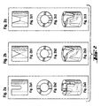
- the invention relates to supported catalysts from an active mass on inert carrier bodies in the form of Hollow cylinders, characterized in that the hollow cylinder one or more notches on the top and / or bottom Have flat side of the hollow cylinder walls, so that the Interior of the hollow cylinder with those surrounding the hollow cylinder Rooms is connected via openings.
- the number of notches on the flat sides of the invention Catalyst depends on the requirements of the corresponding reaction and the dimension of the ring carrier. At least one flat side of the ring is with at least notch. Carrier bodies are preferred in which each of the two flat sides of the ring with one or more Notches are equipped. Catalysts with 2 up to 8 notches on each flat side, particularly preferably 2 to 4 Notches.
- the size of the rings used depends primarily according to the requirements, i.e. the size of the reactor.
- the carrier diameter should then be between 1/2 and 1/10 of the Inner diameter of the reaction tubes are preferred between 1/3 and 1/5.
- Suitable materials are, for example Steatite, Duranit®, silicon carbide, earthenware, porcelain, Silicon dioxide, silicates, aluminum oxide, aluminates or Mixtures of these substances. These can be densely sintered, or be of a porous structure. Rings are preferred made of steatite (densely sintered magnesium silicate) with a height from 4 to 10 mm, an outer diameter from 6 to 10 mm and a wall thickness of 1 to 2 mm.
- the notches according to the invention on the respective sides can regularly or irregularly distributed.
- the order the notches on the flat sides of the rings are preferred chosen so that the notches on the opposite sides always stand "on gap".
- one catalyst according to the invention with two notches each each flat side has the notches on the opposite Flat side offset by 90 degrees.
- the shape of the notches can be semicircular, rectangular, trapezoidal or be V-shaped.
- the individual notches are slightly smaller or significantly larger are than the ring thickness. This way, snagging avoided, among other things, the coating process difficult.
- the depth and width of the notches will be there determined by the mechanical stability of the carrier.
- the dimension of the notches must be at least so large that the Notches not closed when coating with active material become.
- the maximum notch depth and also their width will be limited in that it is in the further manufacturing steps as well as application steps (reactor filling) no destruction of the catalyst may occur.
- Notches with a depth of 1/3 to 1/2 height are preferred of the ring body if notches are made at the top and bottom. Is only one side of the catalyst with the invention Notches, the depth of the notches can also be greater than be half the depth of the ring body. Ultimately it is maximum notch depth from the remaining stability of the Carrier dependent.
- a measuring apparatus with a tube length of 348 cm, an inner diameter of 25 mm, a pressure regulator (0-7.5 bar), a rotameter (0-5 Nm 3 / h), a pre-pressure chamber and a dynamic pressure manometer was filled with catalyst rings.
- the full height was 280 cm for rings A, B, C and D, and 72 cm for rings E and F.
- the mains compressed air (6 bar) was reduced to 2.5 bar with a pressure regulator.
- the required air volumes (3 and 4 Nm 3 / h) were set on the rotameter with a pre-pressure of 1.5 bar. The pressures could then be read on the dynamic pressure gauge. The measurement was carried out at room temperature.
- the measurement was carried out with coated (C, D) and uncoated (A, B) catalyst rings.
- the coated rings were each coated with 8% by weight of catalytic composition consisting of V 2 O 5 / TiO 2 .
- Notched rings were used, each with two notches on the top and two notches on the bottom (A, C). The notches were offset by 90 degrees to each other.
- the ring had a dimension of 7x7x4 mm (outer diameter x height x inner diameter), the notch width was 1.4 mm and the notch depth was 2 mm.
- rings with a dimension of 7x7x4 mm were measured, which were not provided with notches.
- smaller rings measuring 7x4x4 mm were measured (E).
- Catalysts according to the invention a size of 7x7x4 mm have about 20% less Pressure build-up, for the smaller rings with 7x4x4 mm this is Effect even up to 34% larger.
- a catalyst was produced analogously to Example 3, however with the difference that it is based on notched steatite rings Large 7x7x4 mm was applied.
- Example 4 (Preparation of a catalyst according to the invention for the synthesis of acetic acid)
- the catalyst was prepared analogously to DE-A-19649426.
- the active mass consists of oxides of titanium, vanadium, molybdenum and antimony of the empirical formula Ti a V b Mo c Sb d O e (a: 91; b: 7; c: 1; d: 3; e: 207) and in a proportion of 14.4 wt .-% plus 1.6 wt .-% graphite based on the weight of the carrier.
- This active mass was applied to notched steatite rings, each with two notches on the top and two notches on the bottom, and dried. The notches were offset by 90 degrees to each other.
- the rings had a dimension of 7x7x4 mm, the notch width was 1.4 mm and the notch depth was 2 mm.
- the catalyst was prepared analogously to Example 4 with the exception that the active mass is on notched rings with a dimension of 7x7x4 mm (outer diameter x inner diameter x height) was applied.
- Example 5 (Test of the catalysts from Example 3 and Comparative Example 1 using the example of o-xylene oxidation)
- the test was carried out in a tubular reactor with a length of 330 cm and an inner tube diameter of 25 mm.
- the tube was tempered with a circulating salt bath (eutectic melt, made of potassium nitrate and sodium nitrite).
- the reactor was filled with the catalyst according to the invention from example 3 or the catalyst from comparative example 1.
- the catalyst fill height was 280 cm in both tests.
- the salt bath temperature was 365 ° C.
- 4 Nm 3 of an air / o-xylene mixture were passed through this reactor, the o-xylene concentration being 60 g / Nm 3 air and the air / o-xylene mixture before entering the reactor was preheated to 180 ° C.
- thermocouple was installed in the center of the reactor, which made it possible to measure the temperature profile in the tube.
- the reaction gas leaving the reactor was passed through a desublimator to separate the reaction products such as PSA.
- Example 6 (Test of the catalysts from Example 4 and Comparative Example 2 using the example of the oxidation of butane / butene mixtures to acetic acid)
- the catalyst according to the invention from example 4 was introduced into a circulating gas reactor with a reaction tube inner diameter of 25 mm and a filling height of 6000 mm, and was tested according to DE-A 19910866 using the example of an oxidation of a butene / butane mixture. 320 g / h of oxygen, 130 g / h of 1-butene and 56 g / h of n-butane were fed in as the reaction gas. The circulating gas flow was adjusted so that the reactor reached a circulating gas flow of 12,780 g / h in the stable state. The reactor was operated at 11 * 10 5 Pa pressure and 187 ° C coolant temperature.
- the acid was separated from the reaction gas by absorption with 1000 g / h of water (task at the head) in an absorber with a structured packing, an inside diameter of 43 mm and a packing height of 3240 mm at a head temperature of the absorber of 130 ° C.
- a butene conversion of 99.8% and a butane conversion of 83.1% were achieved under these conditions.
- the acetic acid selectivity with respect to the total C 4 conversion was 73 mol%, the formic acid selectivity with respect to the total C 4 conversion was 9 mol%.
- the crude acid concentration was 24% by weight.
- the comparative catalyst from comparative example 2 was used analogously to the above procedure (333 g / h oxygen, 130 g / h 1-butene and 60 g / h n-butane).
- the circulating gas flow was adjusted so that the reactor reached a circulating gas flow of 12520 g / h in the stable state.
- the reactor was operated at 11 * 10 5 Pa pressure and 191 ° C coolant temperature.
- the acid was separated from the reaction gas by absorption with 1000 g / h of water (task at the head) in an absorber with a structured packing, an inside diameter of 43 mm and a packing height of 3240 mm at a head temperature of the absorber of 130 ° C.
- a butene conversion of 99.8% and a butane conversion of 83.8% were achieved under these conditions.
- the acetic acid selectivity with respect to the total C 4 conversion was 70 mol%, the formic acid selectivity with respect to the total C 4 conversion was 8 mol%.
- the crude acid concentration was 23% by weight.
Landscapes
- Chemical & Material Sciences (AREA)
- Organic Chemistry (AREA)
- Engineering & Computer Science (AREA)
- Oil, Petroleum & Natural Gas (AREA)
- Materials Engineering (AREA)
- Chemical Kinetics & Catalysis (AREA)
- Low-Molecular Organic Synthesis Reactions Using Catalysts (AREA)
- Catalysts (AREA)
- Organic Low-Molecular-Weight Compounds And Preparation Thereof (AREA)
Description
Aus EP-B 714700 (US-A 5,677,261) ist auch der Auftrag von trockenem Pulver auf angefeuchtete Trägerkörper bekannt.
Ein weiteres Kriterium besteht darin, daß die Trägermaterialen möglichst kostengünstig produziert werden können. In der Technik haben sich dabei Ringe und Kugeln durchgesetzt, wobei aufgrund des bei den Ringen vorhandenen geringeren Druckverlustes ringförmige Träger immer mehr Anwendung finden.
Viele dieser komplizierten Formen, die vor allem durch extrudieren erhältlich sind, sind auf Grund Ihrer Oberfläche nicht zum Beschichten mittels aktiver Katalysatormasse geeigent, und können somit nur als Vollkontakt verwendet werden.
Zur Staudruckmessung wurde die Netzdruckluft (6 bar) mit einem Druckregler auf 2,5 bar reduziert. Am Rotameter wurden die erforderlichen Luftmengen (3 und 4 Nm3/h) mit einem Vordruck von 1,5 bar eingestellt. Die Drücke konnten dann am Staudruckmanometer abgelesen werden. Die Messung erfolgte bei Raumtemperatur.
Die Messung wurde dabei mit beschichteten (C,D) und unbeschichteten (A,B) Katalysatorringen durchgeführt. Die beschichteten Ringe waren mit jeweils 8 Gew.-% katalytischer Masse, bestehend aus V2O5/TiO2 beschichtet. Zum Einsatz kamen gekerbte Ringe mit jeweils zwei Kerben an der Oberseite und zwei Kerben an der Unterseite (A,C). Die Kerben waren dabei um 90 Grad zueinander versetzt. Der Ring hatte eine Dimension von 7x7x4 mm (Außendurchmesser x Höhe x Innendurchmesser), die Kerbenbreite betrug 1,4 mm und die Kerbentiefe 2 mm. Zum Vergleich wurden Ringe mit einer Dimension von 7x7x4 mm gemessen, die nicht mit Kerben versehen waren.
Zusätzlich wurden kleinere Ringe mit einer Dimension von 7x4x4 mm gemessen (E). Diese Ringe waren auf jeder Seite mit zwei rechteckigen Kerben versehen. Die Kerben waren dabei um 90 Grad zueinander versetzt und hatten jeweils eine Tiefe von 2 mm und eine Breite von 1,4 mm. Als Vergleich hierzu wurden Ringe mit der gleichen Dimension, jedoch ohne Kerben gemessen (F).
Die Ergebnisse aus diesen Messungen sind in Tabelle 1 und Tabelle 2 dargestellt.
| Druck (bar) bei 3 Nm3/h | Druck (bar) bei 4 Nm3/h | ||
| A | Gekerbte Ringe unbeschichtet 7x7x4 mm | 0,069 | 0,106 |
| B | Ungekerbte Ringe unbeschichtet 7x7x4 mm | 0,082 | 0,128 |
| C | Gekerbte Ringe beschichtet 7x7x4 mm | 0,064 | 0,099 |
| D | Ungekerbte Ringe beschichtet 7x7x4 mm | 0,079 | 0,120 |
| E | Gekerbte Ringe unbeschichtet 7x4x4 mm | 0,026 | 0,039 |
| F | Ungekerbte Ringe unbeschichtet 7x4x4 mm | 0,038 | 0,059 |
| Δp (bar) bei 3 Nm3/h | Δp (%) bei 3 Nm3/h | Δp (bar) bei 4 Nm3/h | Δp (%) bei 4 Nm3/h | |
| p(B-A) | 0,012 | 18,8 | 0,022 | 20,8 |
| p(D-C) | 0,015 | 23,4 | 0,021 | 21,2 |
| p(F-E) | 0,012 | 32 | 0,02 | 34 |
Das den Reaktor verlassende Reaktionsgas wurde durch einen Desublimator geleitet, um die Reaktionsprodukte wie PSA abzuscheiden.
Die Ergebnisse der Versuche sind in der folgenden Tabelle 3 dargestellt.
| Ergebnisse der o-Xylol-Oxidationsversuche | |||
| Druckverlust bei 4 Nm3/h | Ausbeute an PSA in Gew-%. | Maximal-Temperatur im Katalysatorbett in °C (= Hot-spot) | |
| erfindungsgemäßer Katalysator | 0,33 bar | ∼113 | 434 |
| Vergleichs-Katalysator | 0,40 bar | ∼111 | 449 |
Die Säureabtrennung aus dem Reaktionsgas erfolgte durch Absorption mit 1000 g/h Wasser (Aufgabe am Kopf) in einem Absorber mit strukturierter Packung, einem Innendurchmesser von 43 mm und einer Packungshöhe von 3240 mm bei einer Kopftemperatur des Absorbers von 130°C.
Unter diesen Bedingungen wurde ein Butenumsatz von 99,8 % und ein Butanumsatz von 83,1 % erreicht.
Unter diesen Bedingungen wurde ein Butenumsatz von 99,8 % und ein Butanumsatz von 83,8 % erreicht. Die Essigsäureselektivität bezüglich des gesamt C4-Umsatzes betrug 70 mol-%, die Ameisensäureselektivität bezüglich des gesamt C4-Umsatzes betrug 8 mol-%. Die Rohsäurekonzentration betrug 23 Gew.-%.
Claims (14)
- Trägerkatalysatoren, bestehend aus einer aktiven Masse auf inerten Trägerkörpern in Form von Hohlzylindern, dadurch gekennzeichnet, daß die Hohlzylinder eine oder mehrere Kerben an der oberen und/oder unteren Flachseite der Hohlzylinderwände besitzen, so daß der Innenraum der Hohlzylinder mit den die Hohlzylinder umgebenden Räumen über Öffnungen verbunden ist.
- Trägerkatalysatoren nach Anspruch 1, dadurch gekennzeichnet, daß die Anzahl der Kerben auf einer Flachseite des Hohlzylinders zwischen 2 und 8 liegt.
- Trägerkatalysatoren nach Anspruch 1 bis 2, dadurch gekennzeichnet, daß die Kerben regelmäßig verteilt sind.
- Trägerkatalysatoren nach Anspruch 1 bis 3, dadurch gekennzeichnet, daß die Kerben unregelmäßig verteilt sind.
- Trägerkatalysatoren nach Anspruch 1 bis 4, dadurch gekennzeichnet, daß die Kerben auf den sich gegenüberliegenden Seiten zueinander "auf Lücke" versetzt angeordnet sind.
- Trägerkatalysatoren nach Anspruch 1 bis 5, dadurch gekennzeichnet, daß die Kerben halbrund, rechteckig, trapezförmig oder V-förmig sind.
- Trägerkatalysatoren nach Anspruch 1 bis 6, dadurch gekennzeichnet, daß die Kerbenbreite größer als die Wandstärke des Hohlzylinders ist.
- Trägerkatalysatoren nach Anspruch 1 bis 7, dadurch gekennzeichnet, daß die Kerbenbreite kleiner als die Wandstärke des Hohlzylinders ist.
- Trägerkatalysatoren nach Anspruch 1 bis 8, dadurch gekennzeichnet, daß die Kerbenbreite so gewählt wird, daß sich die Katalysatorträger untereinander nicht verhaken können.
- Trägerkatalysatoren nach Anspruch 1 bis 9 dadurch gekennzeichnet, daß die Hohlzylinder aus Steatit, Siliciumcarbid, Steingut, Porzellan, Siliciumdioxid, Silicate, Aluminiumoxid, Aluminate oder aus Mischungen dieser Stoffen bestehen.
- Trägerkatalysatoren nach Anspruch 1 bis 10, dadurch gekennzeichnet, daß Hohlzylinder mit einer Höhe von 4 bis 10 mm, einem Außendurchmesser von 6 bis 10 mm und einer Wandstärke von 1 bis 2 mm eingesetzt werden.
- Verwendung von Trägerkatalysatoren nach Anspruch 1 bis 11 bei der Gasphasenoxidation von Kohlenwasserstoffen.
- Verwendung nach Anspruch 12 bei der Gasphasenoxidation von o-Xylol und/oder Naphthalin zu Phthalsäureanhydrid.
- Verwendung nach Anspruch 12 bei der Gasphasenoxidation von gesättigten und/oder ungesättigten Kohlenwasserstoffen zu Essigsäure.
Applications Claiming Priority (2)
| Application Number | Priority Date | Filing Date | Title |
|---|---|---|---|
| DE19959413A DE19959413A1 (de) | 1999-12-09 | 1999-12-09 | Trägerkatalysatoren und deren Verwendung bei der Gasphasenoxidation von Kohlenwasserstoffen |
| DE19959413 | 1999-12-09 |
Publications (2)
| Publication Number | Publication Date |
|---|---|
| EP1108470A1 EP1108470A1 (de) | 2001-06-20 |
| EP1108470B1 true EP1108470B1 (de) | 2002-07-17 |
Family
ID=7932024
Family Applications (1)
| Application Number | Title | Priority Date | Filing Date |
|---|---|---|---|
| EP00124327A Expired - Lifetime EP1108470B1 (de) | 1999-12-09 | 2000-11-16 | Trägerkatalysatoren und deren Verwendung bei der Gasphasenoxidation von Kohlenwasserstoffen |
Country Status (10)
| Country | Link |
|---|---|
| US (1) | US6624114B1 (de) |
| EP (1) | EP1108470B1 (de) |
| JP (1) | JP3757111B2 (de) |
| CN (1) | CN1127374C (de) |
| AT (1) | ATE220572T1 (de) |
| BR (1) | BR0005810B1 (de) |
| DE (2) | DE19959413A1 (de) |
| ES (1) | ES2179804T3 (de) |
| NO (1) | NO321987B1 (de) |
| TW (1) | TWI258390B (de) |
Cited By (1)
| Publication number | Priority date | Publication date | Assignee | Title |
|---|---|---|---|---|
| DE102010052126A1 (de) | 2010-11-22 | 2012-05-24 | Süd-Chemie AG | Katalysatorformkörper für durchströmte Festbettreaktoren |
Families Citing this family (18)
| Publication number | Priority date | Publication date | Assignee | Title |
|---|---|---|---|---|
| DE10159834A1 (de) | 2001-12-06 | 2003-06-26 | Consortium Elektrochem Ind | Verfahren zur Herstellung von gesättigten Carbonsäuren mit ein bis vier C-Atomen durch Gasphasenoxidation von 2-Butanon |
| DE102004005863A1 (de) * | 2004-02-05 | 2005-09-08 | Stockhausen Gmbh | Reaktor mit einem einen Einsatz aufweisenden Wärmetauscherbereich |
| US7297402B2 (en) * | 2004-04-15 | 2007-11-20 | Shell Oil Company | Shaped particle having an asymmetrical cross sectional geometry |
| DE102005019596A1 (de) * | 2005-04-27 | 2006-11-02 | Süd-Chemie AG | Katalysatorträger |
| DK1965911T3 (da) * | 2005-11-23 | 2013-09-16 | Sued Chemie Ip Gmbh & Co Kg | Skal-katalysator, især til oxidation af methanol til formaldehyd, og fremgangsmåde til produktion deraf |
| EP1792651A1 (de) * | 2005-11-23 | 2007-06-06 | Süd-Chemie Ag | Schalenkatalysator, insbesondere zur Oxidation von Methanol zu Formaldehyd sowie Verfahren zu dessen Herstellung |
| JP5300738B2 (ja) * | 2006-12-21 | 2013-09-25 | ビーエーエスエフ ソシエタス・ヨーロピア | 前方層を使用して気相酸化するための触媒系及び方法 |
| DE102007011847A1 (de) | 2007-03-12 | 2008-09-18 | Wacker Chemie Ag | Verfahren zur Herstellung von Essig- und Ameisensäure durch Gasphasenoxidation von Ethanol |
| US7998899B2 (en) * | 2007-11-27 | 2011-08-16 | Shell Oil Company | Catalyst with support structure |
| WO2009068510A2 (en) | 2007-11-27 | 2009-06-04 | Shell Internationale Research Maatschappij B.V. | Catalyst support |
| US7910518B2 (en) * | 2008-03-10 | 2011-03-22 | Sd Lizenzverwertungsgesellschaft Mbh & Co. Kg | Geometrically sized solid shaped carrier for olefin epoxidation catalyst |
| EP2307191B1 (de) * | 2008-07-02 | 2018-08-08 | Basf Se | Verfahren zur herstellung eines oxidischen geometrischen formkörpers |
| US8673245B2 (en) * | 2008-09-22 | 2014-03-18 | Nippon Shokubai Co., Ltd. | Fixed-bed reactor and process for producing acrylic acid using the reactor |
| JP2011140210A (ja) * | 2009-06-24 | 2011-07-21 | Sumitomo Chemical Co Ltd | 成形体およびその製造方法、並びに触媒およびその製造方法 |
| FR2980721B1 (fr) * | 2011-10-04 | 2015-03-13 | IFP Energies Nouvelles | Mise en forme de masses de captation pour la purification d'une charge gaz ou liquide contenant du mercure |
| WO2020061402A1 (en) * | 2018-09-20 | 2020-03-26 | Glaxosmithkline Consumer Healthcare Holdings (Us) Llc | Variable dose container |
| CN112642454A (zh) * | 2019-10-12 | 2021-04-13 | 中国石油化工股份有限公司 | 一种邻二甲苯氧化制苯酐的催化剂及其制备方法 |
| CN113617396A (zh) * | 2021-07-20 | 2021-11-09 | 安徽力天环保科技股份有限公司 | 一种苯酐催化剂及其制备方法 |
Family Cites Families (17)
| Publication number | Priority date | Publication date | Assignee | Title |
|---|---|---|---|---|
| US2408164A (en) | 1942-04-25 | 1946-09-24 | Phillips Petroleum Co | Catalyst preparation |
| US3284762A (en) * | 1965-03-26 | 1966-11-08 | Harry W Kompanek | Mechanical-to-electrical transducer |
| GB1373351A (en) | 1972-02-16 | 1974-11-13 | Monsanto Ltd | Catalyst tablets |
| US3966644A (en) | 1973-08-03 | 1976-06-29 | American Cyanamid Company | Shaped catalyst particles |
| DE2811115A1 (de) | 1978-03-15 | 1979-09-27 | Hoechst Ag | Traeger-katalysator fuer die herstellung von vinylacetat aus ethylen, essigsaeure und sauerstoff in der gasphase |
| US4328130A (en) | 1980-10-22 | 1982-05-04 | Chevron Research Company | Shaped channeled catalyst |
| BE886363A (fr) * | 1980-11-26 | 1981-03-16 | Catalysts & Chem Europ | Catalyseurs de reformage et leur utilisation |
| JPS60216844A (ja) | 1984-04-13 | 1985-10-30 | Nippon Shokubai Kagaku Kogyo Co Ltd | エチレンオキシド製造用銀触媒 |
| DE3445289A1 (de) | 1984-12-12 | 1986-06-19 | Basf Ag, 6700 Ludwigshafen | Geformter katalysator fuer heterogen katalysierte reaktionen |
| NZ217874A (en) | 1985-10-25 | 1989-01-27 | Mobil Oil Corp | Quadrulobe catalysts |
| GB2193907A (en) | 1986-06-24 | 1988-02-24 | Dyson Refractories | Ribbed catalyst bodies |
| GB2197597B (en) | 1986-06-24 | 1990-05-09 | Dyson Refractories | Catalyst bodies |
| EP0464633B1 (de) | 1990-07-03 | 1994-01-19 | Kuraray Co., Ltd. | Katalysator und Verfahren zur Herstellung von ungesättigten Estern |
| ES2046157T1 (es) | 1990-10-04 | 1994-02-01 | Monsanto Company | Estructuras conformadas de catalizadores de oxidacion para la produccion de anhidrido maleico. |
| DE4442346A1 (de) | 1994-11-29 | 1996-05-30 | Basf Ag | Verfahren zur Herstellung eines Katalysators, bestehend aus einem Trägerkörper und einer auf der Oberfläche des Trägerkörpers aufgebrachten katalytisch aktiven Oxidmasse |
| DE19721368A1 (de) | 1997-05-22 | 1998-11-26 | Hoechst Ag | Verfahren zur Herstellung von Vinylacetat |
| US6117812A (en) * | 1998-10-06 | 2000-09-12 | China Petro-Chemical Corporation | Dual functional catalyst of packing type and the catalytic distillation equipment |
-
1999
- 1999-12-09 DE DE19959413A patent/DE19959413A1/de not_active Withdrawn
-
2000
- 2000-11-10 US US09/709,832 patent/US6624114B1/en not_active Expired - Lifetime
- 2000-11-16 AT AT00124327T patent/ATE220572T1/de active
- 2000-11-16 ES ES00124327T patent/ES2179804T3/es not_active Expired - Lifetime
- 2000-11-16 EP EP00124327A patent/EP1108470B1/de not_active Expired - Lifetime
- 2000-11-16 DE DE50000281T patent/DE50000281D1/de not_active Expired - Lifetime
- 2000-12-07 NO NO20006216A patent/NO321987B1/no not_active IP Right Cessation
- 2000-12-07 JP JP2000372601A patent/JP3757111B2/ja not_active Expired - Fee Related
- 2000-12-07 TW TW089126123A patent/TWI258390B/zh not_active IP Right Cessation
- 2000-12-08 BR BRPI0005810-6A patent/BR0005810B1/pt not_active IP Right Cessation
- 2000-12-08 CN CN00132140A patent/CN1127374C/zh not_active Expired - Fee Related
Cited By (2)
| Publication number | Priority date | Publication date | Assignee | Title |
|---|---|---|---|---|
| DE102010052126A1 (de) | 2010-11-22 | 2012-05-24 | Süd-Chemie AG | Katalysatorformkörper für durchströmte Festbettreaktoren |
| WO2012069481A1 (de) | 2010-11-22 | 2012-05-31 | Süd-Chemie AG | Katalysatorformkörper für durchströmte festbettreaktoren |
Also Published As
| Publication number | Publication date |
|---|---|
| DE50000281D1 (de) | 2002-08-22 |
| BR0005810B1 (pt) | 2010-11-30 |
| ATE220572T1 (de) | 2002-08-15 |
| JP2001205107A (ja) | 2001-07-31 |
| JP3757111B2 (ja) | 2006-03-22 |
| EP1108470A1 (de) | 2001-06-20 |
| NO20006216L (no) | 2001-06-11 |
| DE19959413A1 (de) | 2001-06-21 |
| BR0005810A (pt) | 2002-01-02 |
| NO321987B1 (no) | 2006-07-31 |
| NO20006216D0 (no) | 2000-12-07 |
| TWI258390B (en) | 2006-07-21 |
| ES2179804T3 (es) | 2003-02-01 |
| CN1127374C (zh) | 2003-11-12 |
| CN1298763A (zh) | 2001-06-13 |
| US6624114B1 (en) | 2003-09-23 |
Similar Documents
| Publication | Publication Date | Title |
|---|---|---|
| EP1108470A1 (de) | Trägerkatalysatoren und deren Verwendung bei der Gasphasenoxidation von Kohlenwasserstoffen | |
| EP0714700B1 (de) | Verfahren zur Herstellung eines Katalysators, bestehend aus einem Trägerkörper und einer auf der Oberfläche des Trägerkörpers aufgebrachten katalytisch aktiven Oxidmasse | |
| DE3930534C2 (de) | ||
| EP2643086B1 (de) | Katalysatorformkörper für durchströmte festbettreaktoren | |
| EP0951351B1 (de) | Verwendung eines schalenkatalysators zur herstellung von essigsäure durch gasphasenoxidation von ungesättigten c 4-kohlenwasserstoffen | |
| EP1311467B1 (de) | Verfahren zur herstellung von phthalsäureanhydrid | |
| EP1159246A1 (de) | Verfahren der katalytischen gasphasenoxidation von acrolein zu acrylsäure | |
| EP0417722A1 (de) | Katalysator für die katalytische Gasphasenoxidation von Olefinen zu ungesättigten Aldehyden | |
| EP1345689A2 (de) | Verfahren zur herstellung einer mo, bi, fe sowie ni und/oder co enthaltenden multimetalloxidaktivmasse | |
| DE3410799C2 (de) | ||
| EP1670582A1 (de) | Verfahren zur herstellung eines katalysators für gasphasenoxidationen durch beschichten von trägermaterial in einer fliessbettapparatur | |
| EP1478614B1 (de) | Verfahren zur herstellung von phthalsäureanhydrid | |
| DE102005009473A1 (de) | Mehrlagen-Katalysator zur Herstellung von Phthalsäureanhydrid | |
| EP1853381B1 (de) | Verfahren zur herstellung eines mehrlagen-katalysators zur erzeugung von phthalsäureanhydrid | |
| DE102009041960A1 (de) | Verfahren zur Herstellung einer Katalysatoranordnung für die Herstellung von Phthalsäureanhydrid | |
| DE19931902A1 (de) | Verfahren zur Herstellung von monolithischen Oxidationskatalysatoren und deren Verwendung bei der Gasphasenoxidation von Kohlenwasserstoffen | |
| EP1611079B1 (de) | Verfahren der heterogen katalysierten partiellen gasphasenoxidation von acrolein zu acryls ure | |
| EP0612748A1 (de) | Verfahren zur Herstellung von Pyromellitsäuredianhydrid (PMDA) | |
| DE69617556T9 (de) | Verfahren zur Herstellung eines Oxidationskatalysators und Verwendung desselben | |
| WO2021074029A1 (de) | Neues katalysatorsystem für die herstellung von maleinsäureanhydrid durch katalytische oxidation von n-butan | |
| DE102019127789A1 (de) | Neues Katalysatorsystem für die Herstellung von Maleinsäureanhydrid durch katalytische Oxidation von n-Butan | |
| WO2021074028A1 (de) | Neues reaktorsystem fuer die herstellung von maleinsaeureanhydrid durch katalytische oxidation von n-butan | |
| DE3543822A1 (de) | Verfahren zur katalytischen oxidation von 4-tertiaer-butyl-o-xylol | |
| EP2547670A1 (de) | Verfahren zur katalytischen gasphasenoxidation von kohlenwasserstoffen und katalysereaktionsvorrichtung | |
| WO2002016300A1 (de) | Verfahren zur gasphasenpartialoxidation von aromatischen kohlenwasserstoffen |
Legal Events
| Date | Code | Title | Description |
|---|---|---|---|
| PUAI | Public reference made under article 153(3) epc to a published international application that has entered the european phase |
Free format text: ORIGINAL CODE: 0009012 |
|
| 17P | Request for examination filed |
Effective date: 20001116 |
|
| AK | Designated contracting states |
Kind code of ref document: A1 Designated state(s): AT BE CH CY DE DK ES FI FR GB GR IE IT LI LU MC NL PT SE TR |
|
| AX | Request for extension of the european patent |
Free format text: AL;LT;LV;MK;RO;SI |
|
| 17Q | First examination report despatched |
Effective date: 20010601 |
|
| GRAG | Despatch of communication of intention to grant |
Free format text: ORIGINAL CODE: EPIDOS AGRA |
|
| AKX | Designation fees paid |
Free format text: AT BE CH CY DE DK ES FI FR GB GR IE IT LI LU MC NL PT SE TR |
|
| GRAG | Despatch of communication of intention to grant |
Free format text: ORIGINAL CODE: EPIDOS AGRA |
|
| GRAH | Despatch of communication of intention to grant a patent |
Free format text: ORIGINAL CODE: EPIDOS IGRA |
|
| GRAH | Despatch of communication of intention to grant a patent |
Free format text: ORIGINAL CODE: EPIDOS IGRA |
|
| GRAA | (expected) grant |
Free format text: ORIGINAL CODE: 0009210 |
|
| AK | Designated contracting states |
Kind code of ref document: B1 Designated state(s): AT BE CH CY DE DK ES FI FR GB GR IE IT LI LU MC NL PT SE TR |
|
| PG25 | Lapsed in a contracting state [announced via postgrant information from national office to epo] |
Ref country code: IE Free format text: LAPSE BECAUSE OF FAILURE TO SUBMIT A TRANSLATION OF THE DESCRIPTION OR TO PAY THE FEE WITHIN THE PRESCRIBED TIME-LIMIT Effective date: 20020717 Ref country code: GR Free format text: LAPSE BECAUSE OF FAILURE TO SUBMIT A TRANSLATION OF THE DESCRIPTION OR TO PAY THE FEE WITHIN THE PRESCRIBED TIME-LIMIT Effective date: 20020717 Ref country code: TR Free format text: LAPSE BECAUSE OF FAILURE TO SUBMIT A TRANSLATION OF THE DESCRIPTION OR TO PAY THE FEE WITHIN THE PRESCRIBED TIME-LIMIT Effective date: 20020717 |
|
| REF | Corresponds to: |
Ref document number: 220572 Country of ref document: AT Date of ref document: 20020815 Kind code of ref document: T |
|
| REG | Reference to a national code |
Ref country code: GB Ref legal event code: FG4D Free format text: NOT ENGLISH |
|
| REG | Reference to a national code |
Ref country code: CH Ref legal event code: EP |
|
| REG | Reference to a national code |
Ref country code: IE Ref legal event code: FG4D Free format text: GERMAN |
|
| REF | Corresponds to: |
Ref document number: 50000281 Country of ref document: DE Date of ref document: 20020822 |
|
| GBT | Gb: translation of ep patent filed (gb section 77(6)(a)/1977) |
Effective date: 20020902 |
|
| PG25 | Lapsed in a contracting state [announced via postgrant information from national office to epo] |
Ref country code: DK Free format text: LAPSE BECAUSE OF FAILURE TO SUBMIT A TRANSLATION OF THE DESCRIPTION OR TO PAY THE FEE WITHIN THE PRESCRIBED TIME-LIMIT Effective date: 20021017 Ref country code: PT Free format text: LAPSE BECAUSE OF FAILURE TO SUBMIT A TRANSLATION OF THE DESCRIPTION OR TO PAY THE FEE WITHIN THE PRESCRIBED TIME-LIMIT Effective date: 20021017 |
|
| ET | Fr: translation filed | ||
| PG25 | Lapsed in a contracting state [announced via postgrant information from national office to epo] |
Ref country code: LU Free format text: LAPSE BECAUSE OF NON-PAYMENT OF DUE FEES Effective date: 20021116 |
|
| PG25 | Lapsed in a contracting state [announced via postgrant information from national office to epo] |
Ref country code: CY Free format text: LAPSE BECAUSE OF FAILURE TO SUBMIT A TRANSLATION OF THE DESCRIPTION OR TO PAY THE FEE WITHIN THE PRESCRIBED TIME-LIMIT Effective date: 20021130 |
|
| REG | Reference to a national code |
Ref country code: ES Ref legal event code: FG2A Ref document number: 2179804 Country of ref document: ES Kind code of ref document: T3 |
|
| REG | Reference to a national code |
Ref country code: IE Ref legal event code: FD4D Ref document number: 1108470E Country of ref document: IE |
|
| PLBE | No opposition filed within time limit |
Free format text: ORIGINAL CODE: 0009261 |
|
| STAA | Information on the status of an ep patent application or granted ep patent |
Free format text: STATUS: NO OPPOSITION FILED WITHIN TIME LIMIT |
|
| PG25 | Lapsed in a contracting state [announced via postgrant information from national office to epo] |
Ref country code: MC Free format text: LAPSE BECAUSE OF NON-PAYMENT OF DUE FEES Effective date: 20030601 |
|
| 26N | No opposition filed |
Effective date: 20030422 |
|
| REG | Reference to a national code |
Ref country code: GB Ref legal event code: 732E |
|
| REG | Reference to a national code |
Ref country code: CH Ref legal event code: PUE Owner name: WACKER CHEMIE AG Free format text: CONSORTIUM FUER ELEKTROCHEMISCHE INDUSTRIE GMBH#ZIELSTATTSTRASSE 20#81379 MUENCHEN (DE) -TRANSFER TO- WACKER CHEMIE AG#HANNS-SEIDEL-PLATZ 4#81737 MUENCHEN (DE) |
|
| NLS | Nl: assignments of ep-patents |
Owner name: WACKER CHEMIE AG Effective date: 20070516 |
|
| REG | Reference to a national code |
Ref country code: FR Ref legal event code: TP |
|
| PGFP | Annual fee paid to national office [announced via postgrant information from national office to epo] |
Ref country code: CH Payment date: 20081114 Year of fee payment: 9 |
|
| PGFP | Annual fee paid to national office [announced via postgrant information from national office to epo] |
Ref country code: ES Payment date: 20081121 Year of fee payment: 9 Ref country code: FI Payment date: 20081114 Year of fee payment: 9 |
|
| REG | Reference to a national code |
Ref country code: CH Ref legal event code: PL |
|
| PG25 | Lapsed in a contracting state [announced via postgrant information from national office to epo] |
Ref country code: FI Free format text: LAPSE BECAUSE OF NON-PAYMENT OF DUE FEES Effective date: 20091116 |
|
| PG25 | Lapsed in a contracting state [announced via postgrant information from national office to epo] |
Ref country code: CH Free format text: LAPSE BECAUSE OF NON-PAYMENT OF DUE FEES Effective date: 20091130 Ref country code: LI Free format text: LAPSE BECAUSE OF NON-PAYMENT OF DUE FEES Effective date: 20091130 |
|
| REG | Reference to a national code |
Ref country code: ES Ref legal event code: FD2A Effective date: 20111116 |
|
| PG25 | Lapsed in a contracting state [announced via postgrant information from national office to epo] |
Ref country code: ES Free format text: LAPSE BECAUSE OF NON-PAYMENT OF DUE FEES Effective date: 20091117 |
|
| PGFP | Annual fee paid to national office [announced via postgrant information from national office to epo] |
Ref country code: NL Payment date: 20131121 Year of fee payment: 14 |
|
| PGFP | Annual fee paid to national office [announced via postgrant information from national office to epo] |
Ref country code: FR Payment date: 20141119 Year of fee payment: 15 Ref country code: SE Payment date: 20141126 Year of fee payment: 15 |
|
| PGFP | Annual fee paid to national office [announced via postgrant information from national office to epo] |
Ref country code: AT Payment date: 20141126 Year of fee payment: 15 |
|
| REG | Reference to a national code |
Ref country code: NL Ref legal event code: V1 Effective date: 20150601 |
|
| PGFP | Annual fee paid to national office [announced via postgrant information from national office to epo] |
Ref country code: BE Payment date: 20141127 Year of fee payment: 15 |
|
| REG | Reference to a national code |
Ref country code: GB Ref legal event code: 732E Free format text: REGISTERED BETWEEN 20150604 AND 20150610 |
|
| REG | Reference to a national code |
Ref country code: DE Ref legal event code: R081 Ref document number: 50000281 Country of ref document: DE Owner name: BASF SE, DE Free format text: FORMER OWNER: WACKER CHEMIE AG, 81737 MUENCHEN, DE |
|
| PG25 | Lapsed in a contracting state [announced via postgrant information from national office to epo] |
Ref country code: NL Free format text: LAPSE BECAUSE OF NON-PAYMENT OF DUE FEES Effective date: 20150601 |
|
| REG | Reference to a national code |
Ref country code: AT Ref legal event code: MM01 Ref document number: 220572 Country of ref document: AT Kind code of ref document: T Effective date: 20151116 |
|
| REG | Reference to a national code |
Ref country code: FR Ref legal event code: ST Effective date: 20160729 |
|
| PG25 | Lapsed in a contracting state [announced via postgrant information from national office to epo] |
Ref country code: AT Free format text: LAPSE BECAUSE OF NON-PAYMENT OF DUE FEES Effective date: 20151116 Ref country code: SE Free format text: LAPSE BECAUSE OF NON-PAYMENT OF DUE FEES Effective date: 20151117 |
|
| PG25 | Lapsed in a contracting state [announced via postgrant information from national office to epo] |
Ref country code: FR Free format text: LAPSE BECAUSE OF NON-PAYMENT OF DUE FEES Effective date: 20151130 |
|
| PGFP | Annual fee paid to national office [announced via postgrant information from national office to epo] |
Ref country code: GB Payment date: 20161130 Year of fee payment: 17 |
|
| PGFP | Annual fee paid to national office [announced via postgrant information from national office to epo] |
Ref country code: IT Payment date: 20161123 Year of fee payment: 17 |
|
| PG25 | Lapsed in a contracting state [announced via postgrant information from national office to epo] |
Ref country code: BE Free format text: LAPSE BECAUSE OF NON-PAYMENT OF DUE FEES Effective date: 20151130 |
|
| GBPC | Gb: european patent ceased through non-payment of renewal fee |
Effective date: 20171116 |
|
| PG25 | Lapsed in a contracting state [announced via postgrant information from national office to epo] |
Ref country code: IT Free format text: LAPSE BECAUSE OF NON-PAYMENT OF DUE FEES Effective date: 20171116 |
|
| PG25 | Lapsed in a contracting state [announced via postgrant information from national office to epo] |
Ref country code: GB Free format text: LAPSE BECAUSE OF NON-PAYMENT OF DUE FEES Effective date: 20171116 |
|
| PGFP | Annual fee paid to national office [announced via postgrant information from national office to epo] |
Ref country code: DE Payment date: 20190131 Year of fee payment: 19 |
|
| REG | Reference to a national code |
Ref country code: DE Ref legal event code: R119 Ref document number: 50000281 Country of ref document: DE |
|
| PG25 | Lapsed in a contracting state [announced via postgrant information from national office to epo] |
Ref country code: DE Free format text: LAPSE BECAUSE OF NON-PAYMENT OF DUE FEES Effective date: 20200603 |