EP1109082A1 - Génératrice notamment pour pièce d'horlogerie - Google Patents
Génératrice notamment pour pièce d'horlogerie Download PDFInfo
- Publication number
- EP1109082A1 EP1109082A1 EP99124387A EP99124387A EP1109082A1 EP 1109082 A1 EP1109082 A1 EP 1109082A1 EP 99124387 A EP99124387 A EP 99124387A EP 99124387 A EP99124387 A EP 99124387A EP 1109082 A1 EP1109082 A1 EP 1109082A1
- Authority
- EP
- European Patent Office
- Prior art keywords
- generator
- coils
- rotor
- parts
- shaft
- Prior art date
- Legal status (The legal status is an assumption and is not a legal conclusion. Google has not performed a legal analysis and makes no representation as to the accuracy of the status listed.)
- Granted
Links
Images


Classifications
-
- G—PHYSICS
- G04—HOROLOGY
- G04C—ELECTROMECHANICAL CLOCKS OR WATCHES
- G04C10/00—Arrangements of electric power supplies in time-pieces
-
- H—ELECTRICITY
- H02—GENERATION; CONVERSION OR DISTRIBUTION OF ELECTRIC POWER
- H02K—DYNAMO-ELECTRIC MACHINES
- H02K3/00—Details of windings
Definitions
- the present invention relates to a generator of the watchmaking type. and a watch movement equipped with such a generator, in particular for wristwatch.
- batteries or accumulators are for all applications, and in particular for a watch, a factor limiting characteristics of the device. Indeed, changing or recharging these batteries or accumulators affects the availability and reliability of the watch.
- the traditional mechanical watch has a definite advantage in watchmaking technique: such a watch is available permanently. Energy recharging - this being purely mechanical - is simply done by winding the watch mechanism.
- This type of watch uses a manual winding device or automatic generally coupled to a regulation device named in the use "Swiss anchor escapement”. This regulation device allows difficult to obtain high precision. This system is also relatively expensive.
- the other big family concerns the classic quartz watch.
- a battery simultaneously powers an electric motor and a regulation of the running of this engine.
- the rotation of the motor is controlled by a nominal frequency provided by a quartz. This allows to have a good precision for time indication.
- this device is relatively noisy because the advance of the seconds wheel is jerky and the battery must be changed periodically.
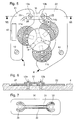
- FIG. 1 The arrangement of the generator according to this prior art is illustrated in Figure 1 attached, showing a top view of a watch movement partially assembled, and in attached figure 2, which is a cross section of Figure 1.
- This generator comprises a rotor having two flanges 8 arranged on either side of three flat coils 11 forming the stator and offset by 120 ° relative to each other relative to the axis of the rotor, in the same plane orthogonal to it.
- a printed circuit 6 is fixed to the plate 4 and serves as a support for the coils 11.
- Power supply to electronic circuit 10, low consumption of energy, is provided by an electric generator - consisting of the rotor shaft 5, flanges 8, magnets 9 and coils 11 - driven assembly via the kinematic link 3 by the barrel device 2. Mechanical energy stored in the barrel 2 therefore drives the rotor. The passage of magnets 9 to proximity of the coils 11 generates a substantially induced voltage sinusoidal across these coils 11.
- Figure 3 attached schematically highlights the fact that the assembly of the monobloc rotor - consisting of parts 5, 8 and 9 - is done currently by lateral insertion of the shaft 5 between two fixed coils 11.
- the rotor, monobloc cannot be inserted vertically since the three coils 11 are fixed and the flanges 8 located on either side of these coils should partially cover them.
- the coils 11 have a spacing, referenced DMin in Figure 3 attached, at least as wide as the shaft 5 of the rotor, having a diameter D in the middle, to allow the introduction of this tree laterally to its final location at center of the three coils.
- the invention aims to remedy these drawbacks. It relates to this effect on a clock-type generator comprising on the one hand a rotor comprising two flanges carried by a tree, this tree and these flanges being integral in rotation in running order, magnets being fixed to each flange in even number - two consecutive or opposite magnets being of opposite polarity - and further comprising a stator formed at least three coils of axes parallel to that of the rotor and arranged on a support, these coils being arranged between the two flanges provided with magnets after assembling this generator and leaving space between them sufficient central for said rotor shaft.
- This generator is characterized in that the coil holder is formed from at least two parts which can be assembled with the rotor independently of each other and bearing each at least one coil, and in that means are provided for electrical connection between these at least two parts, the distance between any two adjacent coils after mounting the generator being less than the diameter D of the rotor shaft.
- the generator of the watchmaking type is characterized in that the reel support presents at least two rigid or stiffened parts each carrying at least one coil and a deformable part materially connecting these two rigid parts, this deformable part being elastically deformed during assembly of the rotor with stator to allow lateral passage of the shaft of this rotor between two coils, the distance between two adjacent coils any after assembly of the generator being less than the diameter D of the rotor shaft.
- the features of the invention according to the first or second above-mentioned embodiment it is possible to use so optimal coupling space between the rotor magnets and the coils statorics.
- the diameter of the rotor shaft is no longer a limiting parameter the dimensions of the stator coils.
- the yield of the generator and / or the size of the stator are improved.
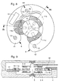
- Figure 4 shows the arrangement of the rotor including the upper flange 8 and the magnets 9 which they carry are shown in broken lines.
- the tree 5 of the rotor has in its middle a diameter D which is greater than the distance separating any two adjacent coils.
- the coils 11a, 11b and 11c define a central space 13 where the shaft 5 of the rotor is arranged.
- the overlap between the coils 11a, 11b and 11c and the flanges 8 of the rotor is more important than in the case of the prior art shown in Figure 3. Note that by increasing the dimensions of the flanges 8 and of the coils, it is possible to obtain a configuration in which the coils touch. So the design of the generator according to the invention, as will be described more precisely by the continued, increases the magnet-coil coupling of the generator and / or minimize the size of the stator.
- FIGS. 5 to 7 Using FIGS. 5 to 7, a first mode of description will be described below. realization of the invention.
- the stator of the generator is formed by a support 6 comprising two separate plates 21 and 22 and three coils 11a, 11b and 11c.
- Plate 22 carries the coils 11b and 11c.
- the coil 11a can be introduced between the flanges 8 of the rotor independently of the introduction of the coils 11b and 11c.
- the plate 21 is fixed to the body 4 of a watch movement using two screws 12 and 12a.
- the plate 22 is fixed to this body 4 by means two screws 12 and 12b.
- the plates 21 and 22 are connected by a fixed bridge 30 to the body 4 using the screws 12a and 12b.
- This bridge 30 serves to establish a electrical connection between two electrical tracks 25 and 26 shown partially in Figure 5.
- Bridge 30 therefore has two tracks 31 and 32 on its face located opposite plates 21 and 22.
- the ends of tracks 31 and 32 have ends in an arc arranged around the holes 33 and 34 provided respectively for the passage of the screws 12a and 12b.
- tracks 31 and 32 can be arranged differently. It is enough that these tracks make it possible to establish an electrical connection between tracks 25 and 26 provided on the one hand on the plate 21 and on the other hand on the plate 22.
- the stator 6 differs from the previous mode in that that it is formed of two plates 41 and 42 partially superimposed one at the other after assembly of the generator.
- overlay region 44 between the plates 41 and 42 are arranged contact pads 46 and 47 on each of the plates 41 and 42.
- the two tracks 46, respectively 47 are located opposite one another so as to ensure an electrical connection between the electrical tracks 25 and 26 provided on the one hand on the upper face of the plate 41 and on the other hand on the underside of the plate 42.
- the lower part 41 carries the coil 11a on an upper surface 48 while the upper part 42 carries the coils 11b and 11c on a lower surface 49.
- the surfaces 48 and 49 are located at a certain distance from the contact plane between the plates 41 and 42 in the region of superposition 44. This to allow the three coils 11a, 11b and 11c to be arranged in the same general plane between the flanges 8 of the rotor.
- the coil 11a is brought separately from the coils 11b and 11c. These coils are introduced laterally between the flanges 8 and are thus brought into their final relative position during assembly of the stator with rotor. Once the plates 41 and 42 are in place, these are fixed to the body 4 of the watch movement by means of screws 12 and 12c, the screw 12c being provided in the superposition region 44.
- the generator is characterized by the fact that the stator is formed by a support 66 comprising two rigid substrates 51 and 52 and a flexible film 54 having a portion 56 so deformable elastic.
- the flexible film is superimposed on the rigid substrate 51 and 52 at least in the region of the coils 11a, 11b and 11c.
- Substrate 51 carries the coil 11a while the substrate 52 carries the coils 11b and 11c.
- the flexible film 54 is glued against the underside of the substrates 51 and 52.
- it is only inserted between these substrates and the body 4 of the clockwork movement, the flexible film 54 thus being maintained fixedly in the two regions of superposition on the substrate 51 and 52 which are fixed to the body 4 by means of screws 12.
- the electrical tracks connecting the coils are arranged on the flexible film 54, two tracks 58 and 59 crossing the deformable region 56.
- the substrates 51 and 52 respectively have parts 61 and 62 superimposed on the coils 11a, 11b and 11c respectively. These coils are therefore partially inserted into recesses defined between these parts 61, 62 and the flexible film 54. They are fixed to the substrates 61 and 62 by collage. An adhesive film can also be provided between the coils and the flexible film 54 in the overlapping regions.
- Figure 12 is shown in section an alternative embodiment.
- This variant is essentially distinguished in that the flexible film 54 on which are printed the conductive tracks is located above the rigid substrates 51 and 52. In the overlapping regions of the flexible film and rigid substrates, the flexible film is rigidly assembled to these substrates, in particular by bonding.
- the coils 11a to 11c are arranged on the flexible film to which they rigidly adhere also by gluing. This variant makes it easier to assemble the various elements of the generator.
- the mounting of the stator and of the rotor is carried out by spreading the coils 11a and 11c and by deforming elastically the part 56 of the flexible film 54 to allow the shaft 5 of the rotor to be introduced into the central region 13 defined by the three coils.
- This last embodiment has the advantage of having before assembly of the rotor and the stator, a one-piece stator or previously assembled.
- the deformable part 56 is formed so as to be able to undergo the slight deformation necessary for the passage of the shaft 5 without this deteriorates the two conductive tracks 58 and 59 crossing this region 56.
Landscapes
- Engineering & Computer Science (AREA)
- Power Engineering (AREA)
- Physics & Mathematics (AREA)
- General Physics & Mathematics (AREA)
- Permanent Magnet Type Synchronous Machine (AREA)
- Electromechanical Clocks (AREA)
- Electrophonic Musical Instruments (AREA)
- Insulation, Fastening Of Motor, Generator Windings (AREA)
- Reciprocating, Oscillating Or Vibrating Motors (AREA)
Abstract
Description
- la figure 4 est une coupe, similaire à la figure 3, montrant l'agencement selon l'invention des bobines statoriques et de l'arbre du rotor une fois la génératrice montée;
- la figure 5 est une vue de dessus et la figure 6 est une vue en coupe d'un premier mode de réalisation comportant un ensemble formé d'un substrat en deux parties reliées par un pont;
- la figure 7 montre l'agencement de la connexion électrique entre les deux parties du substrat du premier mode de réalisation;
- la figure 8 est une vue de dessus et la figure 9 une vue en coupe d'un deuxième mode de réalisation d'une génératrice selon l'invention;
- la figure 10 est une vue de dessus et la figure 11 une vue en coupe d'un troisième mode de réalisation d'une génératrice selon l'invention; et
- la figure 12 est une vue en coupe d'une variante du troisième mode de réalisation.
Claims (10)
- Génératrice du type horloger comprenant d'une part un rotor comportant deux flasques (8) portés par un arbre (5) présentant un diamètre D en son milieu, des aimants (9) étant fixés à chaque flasque en nombre pair - deux aimants consécutifs ou en vis-à-vis étant de polarité opposée - cette génératrice comprenant d'autre part un stator formé d'au moins trois bobines (11a, 11b, 11c) d'axes parallèles à celui dudit rotor et fixées sur un support, ces bobines étant agencées entre les deux flasques munis d'aimants après l'assemblage de cette génératrice et ménageant entre elles un espace central (13) suffisant pour l'arbre (5) du rotor, caractérisée en ce que ledit support de bobines est formé d'au moins deux parties pouvant être assemblées avec ledit rotor indépendamment l'une de l'autre et portant chacune au moins une bobine, et en ce qu'il est prévu des moyens de connexion électrique entre ces au moins deux parties, la distance séparant deux bobines adjacentes quelconques après montage de la génératrice étant inférieure audit diamètre D dudit arbre.
- Génératrice selon la revendication 1, caractérisée en ce que lesdits moyens de connexion électrique sont formés par un pont reliant lesdites deux parties du support de bobines, ce pont présentant des pistes conductrices agencées sur sa face en regard de ces deux parties.
- Génératrice selon la revendication 1, caractérisée en ce que ledit support de bobines est formé de deux parties partiellement superposées l'une à l'autre après montage de cette génératrice, ces deux parties présentant respectivement dans la région de superposition au moins des premières et deuxièmes plages ou pistes de contact reliées électriquement l'une à l'autre.
- Génératrice selon la revendication 3, caractérisée en ce que la partie du support située au niveau inférieur relativement à l'autre partie du support porte sa au moins une bobine sur une surface supérieure alors que cette autre partie porte sa au moins une bobine sur une surface inférieure de manière que l'ensemble des bobines portées par ledit support sont situées dans un même plan général après montage de la génératrice.
- Génératrice du type horloger comprenant d'une part un rotor comportant deux flasques (8) portés par un arbre (5) présentant un diamètre D en son milieu, des aimants (9) étant fixés à chaque flasque en nombre pair - deux aimants consécutifs ou en vis-à-vis étant de polarité opposée - cette génératrice comprenant d'autre part un stator formé d'au moins trois bobines (11a, 11b, 11c) d'axes parallèles à celui dudit rotor et fixées sur un support, ces bobines étant agencées entre les deux flasques munis d'aimants après l'assemblage de cette génératrice et ménageant entre elles un espace central (13) suffisant pour l'arbre (5) du rotor, caractérisé en ce que ledit support de bobines présente au moins deux parties rigides ou rigidifiées portant chacune au moins une bobine et une partie déformable reliant matériellement ces deux parties rigides, cette partie déformable étant déformée élastiquement lors de l'assemblage dudit rotor et dudit stator pour permettre le passage latéral dudit arbre entre deux bobines, la distance séparant deux bobines adjacentes quelconques après montage de la génératrice étant inférieure audit diamètre D dudit arbre.
- Génératrice selon la revendication 5, caractérisée en ce que ledit support est formé par un film souple sur lequel sont déposées des pistes conductrices et par au moins deux substrats rigides au moins partiellement superposés audit film souple auquel ils sont solidement assemblés au moins après montage de la génératrice, ledit film définissant ladite partie déformable et lesdits au moins deux substrats rigides définissant respectivement lesdites au moins deux parties rigides ou rigidifiées.
- Génératrice selon la revendication 6, caractérisée en ce que lesdits deux substrats rigides sont fixés au corps dans lequel est monté ledit rotor, ledit film souple étant placé entre ce corps et les deux substrats rigides.
- Génératrice selon la revendication 7, caractérisée en ce que les deux substrats rigides présentent des parties (61, 62) superposées aux bobines et situées du côté opposé au film souple relativement à ces bobines.
- Génératrice selon la revendication 6, caractérisée en ce que ledit film souple est collé sur lesdits substrats rigides, lesdites bobines étant fixées rigidement sur ce film souple.
- Mouvement horloger caractérisé en ce qu'il est équipé d'une génératrice selon l'une des revendications 1 à 9.
Priority Applications (7)
| Application Number | Priority Date | Filing Date | Title |
|---|---|---|---|
| DE69940638T DE69940638D1 (de) | 1999-12-07 | 1999-12-07 | Generator insbesondere für Uhrwerk |
| AT99124387T ATE426842T1 (de) | 1999-12-07 | 1999-12-07 | Generator insbesondere fur uhrwerk |
| EP99124387A EP1109082B1 (fr) | 1999-12-07 | 1999-12-07 | Génératrice notamment pour pièce d'horlogerie |
| US09/715,127 US6469959B1 (en) | 1999-12-07 | 2000-11-20 | Generator in particular for a timepiece |
| JP2000369522A JP4545918B2 (ja) | 1999-12-07 | 2000-12-05 | 特に時計のための発電機およびそれを備えたムーブメント |
| CNB001350358A CN1145088C (zh) | 1999-12-07 | 2000-12-07 | 用于时钟类型的发生器以及使用这种发生器的时钟机构 |
| HK02100363.7A HK1038801B (zh) | 1999-12-07 | 2002-01-16 | 用於時鐘類型的發生器以及使用這種發生器的時鐘機構 |
Applications Claiming Priority (1)
| Application Number | Priority Date | Filing Date | Title |
|---|---|---|---|
| EP99124387A EP1109082B1 (fr) | 1999-12-07 | 1999-12-07 | Génératrice notamment pour pièce d'horlogerie |
Publications (2)
| Publication Number | Publication Date |
|---|---|
| EP1109082A1 true EP1109082A1 (fr) | 2001-06-20 |
| EP1109082B1 EP1109082B1 (fr) | 2009-03-25 |
Family
ID=8239549
Family Applications (1)
| Application Number | Title | Priority Date | Filing Date |
|---|---|---|---|
| EP99124387A Expired - Lifetime EP1109082B1 (fr) | 1999-12-07 | 1999-12-07 | Génératrice notamment pour pièce d'horlogerie |
Country Status (7)
| Country | Link |
|---|---|
| US (1) | US6469959B1 (fr) |
| EP (1) | EP1109082B1 (fr) |
| JP (1) | JP4545918B2 (fr) |
| CN (1) | CN1145088C (fr) |
| AT (1) | ATE426842T1 (fr) |
| DE (1) | DE69940638D1 (fr) |
| HK (1) | HK1038801B (fr) |
Cited By (3)
| Publication number | Priority date | Publication date | Assignee | Title |
|---|---|---|---|---|
| CH707787A1 (fr) * | 2013-03-25 | 2014-09-30 | Richemont Int Sa | Organe régulateur pour montre bracelet et procédé d'assemblage d'un organe régulateur pour montre bracelet. |
| EP3438763A1 (fr) | 2017-08-04 | 2019-02-06 | The Swatch Group Research and Development Ltd | Mouvement horloger muni d'un transducteur électromagnétique |
| EP3982208A1 (fr) | 2020-10-08 | 2022-04-13 | The Swatch Group Research and Development Ltd | Procede de fabrication d'une pluralite de generatrices adaptees a une application horlogere |
Families Citing this family (3)
| Publication number | Priority date | Publication date | Assignee | Title |
|---|---|---|---|---|
| ATE424575T1 (de) * | 1999-11-12 | 2009-03-15 | Asulab Sa | Generator für zeitmessgerät |
| US7501726B1 (en) * | 2004-07-28 | 2009-03-10 | The United States Of America As Represented By The Secretary Of The Navy | Micro-electro-mechanical system (MEMS) and apparatus for generating power responsive to mechanical vibration |
| CN102414969B (zh) * | 2009-03-06 | 2015-08-12 | 鲁梅戴尼技术公司 | 用于响应于机械振动产生电力的装置 |
Citations (2)
| Publication number | Priority date | Publication date | Assignee | Title |
|---|---|---|---|---|
| EP0751445A1 (fr) * | 1995-06-27 | 1997-01-02 | Asulab S.A. | Générateur électrique pour pièce d'horlogerie |
| EP0905587A1 (fr) * | 1997-09-26 | 1999-03-31 | Seiko Epson Corporation | Montre mécanique réglée électriquement |
Family Cites Families (5)
| Publication number | Priority date | Publication date | Assignee | Title |
|---|---|---|---|---|
| JPS5746218Y2 (fr) * | 1975-12-20 | 1982-10-12 | ||
| JPS63109562U (fr) * | 1986-12-26 | 1988-07-14 | ||
| KR950001429Y1 (ko) * | 1988-01-25 | 1995-03-06 | 세이꼬 엡슨 가부시끼가이샤 | 발전장치 부착 전자 팔목시계 |
| EP0706099A1 (fr) * | 1994-10-03 | 1996-04-10 | Zafferri, Roberto | Moteur pas-à-pas épicycloidal |
| JPH11196558A (ja) * | 1997-10-28 | 1999-07-21 | Fumio Uchiyama | 回転電機のステータコイル |
-
1999
- 1999-12-07 EP EP99124387A patent/EP1109082B1/fr not_active Expired - Lifetime
- 1999-12-07 AT AT99124387T patent/ATE426842T1/de not_active IP Right Cessation
- 1999-12-07 DE DE69940638T patent/DE69940638D1/de not_active Expired - Lifetime
-
2000
- 2000-11-20 US US09/715,127 patent/US6469959B1/en not_active Expired - Lifetime
- 2000-12-05 JP JP2000369522A patent/JP4545918B2/ja not_active Expired - Fee Related
- 2000-12-07 CN CNB001350358A patent/CN1145088C/zh not_active Expired - Fee Related
-
2002
- 2002-01-16 HK HK02100363.7A patent/HK1038801B/zh not_active IP Right Cessation
Patent Citations (2)
| Publication number | Priority date | Publication date | Assignee | Title |
|---|---|---|---|---|
| EP0751445A1 (fr) * | 1995-06-27 | 1997-01-02 | Asulab S.A. | Générateur électrique pour pièce d'horlogerie |
| EP0905587A1 (fr) * | 1997-09-26 | 1999-03-31 | Seiko Epson Corporation | Montre mécanique réglée électriquement |
Cited By (6)
| Publication number | Priority date | Publication date | Assignee | Title |
|---|---|---|---|---|
| CH707787A1 (fr) * | 2013-03-25 | 2014-09-30 | Richemont Int Sa | Organe régulateur pour montre bracelet et procédé d'assemblage d'un organe régulateur pour montre bracelet. |
| WO2014154467A1 (fr) * | 2013-03-25 | 2014-10-02 | Richemont International Sa | Organe régulateur pour montre bracelet et procédé d'assemblage d'un organe régulateur pour montre bracelet |
| EP3438763A1 (fr) | 2017-08-04 | 2019-02-06 | The Swatch Group Research and Development Ltd | Mouvement horloger muni d'un transducteur électromagnétique |
| US10948881B2 (en) | 2017-08-04 | 2021-03-16 | The Swatch Group Research And Development Ltd | Timepiece movement fitted with an electromagnetic transducer |
| EP3982208A1 (fr) | 2020-10-08 | 2022-04-13 | The Swatch Group Research and Development Ltd | Procede de fabrication d'une pluralite de generatrices adaptees a une application horlogere |
| US12066793B2 (en) | 2020-10-08 | 2024-08-20 | The Swatch Group Research And Development Ltd | Method for manufacturing a plurality of generators adapted for a horological application |
Also Published As
| Publication number | Publication date |
|---|---|
| DE69940638D1 (de) | 2009-05-07 |
| JP2001211622A (ja) | 2001-08-03 |
| CN1145088C (zh) | 2004-04-07 |
| HK1038801B (zh) | 2005-02-04 |
| ATE426842T1 (de) | 2009-04-15 |
| HK1038801A1 (en) | 2002-03-28 |
| US6469959B1 (en) | 2002-10-22 |
| JP4545918B2 (ja) | 2010-09-15 |
| EP1109082B1 (fr) | 2009-03-25 |
| CN1305126A (zh) | 2001-07-25 |
Similar Documents
| Publication | Publication Date | Title |
|---|---|---|
| EP1521142B1 (fr) | Pièce d'horlogerie ayant un mouvement mécanique associé à un régulateur électronique | |
| EP1521141B1 (fr) | Pièce d'horlogerie ayant un mouvement mécanique associé à un régulateur électronique | |
| EP1099990B1 (fr) | Génératrice pour pièce d'horlogerie | |
| WO1997023943A1 (fr) | Moteur diphase, notamment un moteur d'horlogerie ou un moteur pour l'entrainement d'une aiguille d'un afficheur | |
| EP3299908B1 (fr) | Montre à remontage automatique | |
| EP3182226A1 (fr) | Montre squelette-solaire | |
| EP0625738B1 (fr) | Alarme silencieuse électromagnétique | |
| EP1109082B1 (fr) | Génératrice notamment pour pièce d'horlogerie | |
| WO1999049556A1 (fr) | Convertisseur d'energie mecanique en energie electrique et appareil electronique muni d'un tel convertisseur | |
| EP1109083B1 (fr) | Mouvement du type horloger équipé d'une génératrice | |
| EP3944027B1 (fr) | Objet portable, notamment montre bracelet, comprenant un dispositif d'alimentation muni d'un convertisseur electromecanique | |
| EP0698957B1 (fr) | Transducteur électromécanique comportant deux rotors | |
| EP2979141A1 (fr) | Organe régulateur pour montre bracelet et procédé d'assemblage d'un organe régulateur pour montre bracelet | |
| EP0681228A1 (fr) | Dispositif de couplage entre une source d'énergie mécanique et une génératrice électrique dans une pièce d'horlogerie | |
| EP0012460B1 (fr) | Stator monobloc pour moteur pas à pas d'horlogerie | |
| EP2264555B1 (fr) | Transducteur électromécanique de petites dimensions, notamment génératrice horlogère | |
| EP0790540B1 (fr) | Transducteur électromécanique à aimants permanents multipolaires | |
| EP0661794B1 (fr) | Transducteur électromécanique cylindrique | |
| EP3964897B1 (fr) | Pièce d'horlogerie comprenant une génératrice et procédé de montage d'une telle piece d'horlogerie | |
| CH712957A2 (fr) | Montre à remontage automatique. | |
| FR2690765A1 (fr) | Mouvement analogique pour pièce d'horlogerie. | |
| EP2343747A1 (fr) | Dispositif générateur d'énergie électrique pour appareil portable, notamment pour pièce d'horlogerie | |
| CH722152A2 (fr) | Montre munie d'une génératrice mécano-électrique | |
| CH720902A1 (fr) | Cellule photovoltaïque montée sur le mouvement | |
| CH701968B1 (fr) | Source d'énergie pour sonnerie et pièce d'horlogerie munie d'une telle source d'énergie. |
Legal Events
| Date | Code | Title | Description |
|---|---|---|---|
| PUAI | Public reference made under article 153(3) epc to a published international application that has entered the european phase |
Free format text: ORIGINAL CODE: 0009012 |
|
| AK | Designated contracting states |
Kind code of ref document: A1 Designated state(s): AT BE CH CY DE DK ES FI FR GB GR IE IT LI LU MC NL PT SE |
|
| AX | Request for extension of the european patent |
Free format text: AL;LT;LV;MK;RO;SI |
|
| 17P | Request for examination filed |
Effective date: 20011220 |
|
| AKX | Designation fees paid |
Free format text: AT BE CH CY DE DK ES FI FR GB GR IE IT LI LU MC NL PT SE |
|
| GRAP | Despatch of communication of intention to grant a patent |
Free format text: ORIGINAL CODE: EPIDOSNIGR1 |
|
| GRAS | Grant fee paid |
Free format text: ORIGINAL CODE: EPIDOSNIGR3 |
|
| GRAA | (expected) grant |
Free format text: ORIGINAL CODE: 0009210 |
|
| AK | Designated contracting states |
Kind code of ref document: B1 Designated state(s): AT BE CH CY DE DK ES FI FR GB GR IE IT LI LU MC NL PT SE |
|
| REG | Reference to a national code |
Ref country code: GB Ref legal event code: FG4D Free format text: NOT ENGLISH |
|
| REG | Reference to a national code |
Ref country code: CH Ref legal event code: EP |
|
| REG | Reference to a national code |
Ref country code: IE Ref legal event code: FG4D Free format text: LANGUAGE OF EP DOCUMENT: FRENCH |
|
| REF | Corresponds to: |
Ref document number: 69940638 Country of ref document: DE Date of ref document: 20090507 Kind code of ref document: P |
|
| REG | Reference to a national code |
Ref country code: CH Ref legal event code: NV Representative=s name: ICB INGENIEURS CONSEILS EN BREVETS SA |
|
| PG25 | Lapsed in a contracting state [announced via postgrant information from national office to epo] |
Ref country code: SE Free format text: LAPSE BECAUSE OF FAILURE TO SUBMIT A TRANSLATION OF THE DESCRIPTION OR TO PAY THE FEE WITHIN THE PRESCRIBED TIME-LIMIT Effective date: 20090625 Ref country code: AT Free format text: LAPSE BECAUSE OF FAILURE TO SUBMIT A TRANSLATION OF THE DESCRIPTION OR TO PAY THE FEE WITHIN THE PRESCRIBED TIME-LIMIT Effective date: 20090325 |
|
| NLV1 | Nl: lapsed or annulled due to failure to fulfill the requirements of art. 29p and 29m of the patents act | ||
| RAP2 | Party data changed (patent owner data changed or rights of a patent transferred) |
Owner name: ASULAB S.A. |
|
| REG | Reference to a national code |
Ref country code: IE Ref legal event code: FD4D |
|
| PG25 | Lapsed in a contracting state [announced via postgrant information from national office to epo] |
Ref country code: PT Free format text: LAPSE BECAUSE OF FAILURE TO SUBMIT A TRANSLATION OF THE DESCRIPTION OR TO PAY THE FEE WITHIN THE PRESCRIBED TIME-LIMIT Effective date: 20090831 Ref country code: ES Free format text: LAPSE BECAUSE OF FAILURE TO SUBMIT A TRANSLATION OF THE DESCRIPTION OR TO PAY THE FEE WITHIN THE PRESCRIBED TIME-LIMIT Effective date: 20090706 |
|
| PG25 | Lapsed in a contracting state [announced via postgrant information from national office to epo] |
Ref country code: NL Free format text: LAPSE BECAUSE OF FAILURE TO SUBMIT A TRANSLATION OF THE DESCRIPTION OR TO PAY THE FEE WITHIN THE PRESCRIBED TIME-LIMIT Effective date: 20090325 |
|
| PG25 | Lapsed in a contracting state [announced via postgrant information from national office to epo] |
Ref country code: IE Free format text: LAPSE BECAUSE OF FAILURE TO SUBMIT A TRANSLATION OF THE DESCRIPTION OR TO PAY THE FEE WITHIN THE PRESCRIBED TIME-LIMIT Effective date: 20090325 Ref country code: DK Free format text: LAPSE BECAUSE OF FAILURE TO SUBMIT A TRANSLATION OF THE DESCRIPTION OR TO PAY THE FEE WITHIN THE PRESCRIBED TIME-LIMIT Effective date: 20090325 |
|
| PGFP | Annual fee paid to national office [announced via postgrant information from national office to epo] |
Ref country code: FI Payment date: 20091126 Year of fee payment: 11 |
|
| PLBE | No opposition filed within time limit |
Free format text: ORIGINAL CODE: 0009261 |
|
| STAA | Information on the status of an ep patent application or granted ep patent |
Free format text: STATUS: NO OPPOSITION FILED WITHIN TIME LIMIT |
|
| 26N | No opposition filed |
Effective date: 20091229 |
|
| PGFP | Annual fee paid to national office [announced via postgrant information from national office to epo] |
Ref country code: GB Payment date: 20091125 Year of fee payment: 11 |
|
| BERE | Be: lapsed |
Owner name: ASULAB S.A. Effective date: 20091231 |
|
| PG25 | Lapsed in a contracting state [announced via postgrant information from national office to epo] |
Ref country code: MC Free format text: LAPSE BECAUSE OF NON-PAYMENT OF DUE FEES Effective date: 20100701 |
|
| PG25 | Lapsed in a contracting state [announced via postgrant information from national office to epo] |
Ref country code: GR Free format text: LAPSE BECAUSE OF FAILURE TO SUBMIT A TRANSLATION OF THE DESCRIPTION OR TO PAY THE FEE WITHIN THE PRESCRIBED TIME-LIMIT Effective date: 20090626 Ref country code: BE Free format text: LAPSE BECAUSE OF NON-PAYMENT OF DUE FEES Effective date: 20091231 |
|
| PG25 | Lapsed in a contracting state [announced via postgrant information from national office to epo] |
Ref country code: LU Free format text: LAPSE BECAUSE OF NON-PAYMENT OF DUE FEES Effective date: 20091207 |
|
| GBPC | Gb: european patent ceased through non-payment of renewal fee |
Effective date: 20101207 |
|
| PG25 | Lapsed in a contracting state [announced via postgrant information from national office to epo] |
Ref country code: FI Free format text: LAPSE BECAUSE OF NON-PAYMENT OF DUE FEES Effective date: 20101207 |
|
| PG25 | Lapsed in a contracting state [announced via postgrant information from national office to epo] |
Ref country code: CY Free format text: LAPSE BECAUSE OF FAILURE TO SUBMIT A TRANSLATION OF THE DESCRIPTION OR TO PAY THE FEE WITHIN THE PRESCRIBED TIME-LIMIT Effective date: 20090325 |
|
| PG25 | Lapsed in a contracting state [announced via postgrant information from national office to epo] |
Ref country code: GB Free format text: LAPSE BECAUSE OF NON-PAYMENT OF DUE FEES Effective date: 20101207 |
|
| PGFP | Annual fee paid to national office [announced via postgrant information from national office to epo] |
Ref country code: FR Payment date: 20141217 Year of fee payment: 16 |
|
| PGFP | Annual fee paid to national office [announced via postgrant information from national office to epo] |
Ref country code: DE Payment date: 20151119 Year of fee payment: 17 Ref country code: IT Payment date: 20151120 Year of fee payment: 17 |
|
| REG | Reference to a national code |
Ref country code: FR Ref legal event code: ST Effective date: 20160831 |
|
| PG25 | Lapsed in a contracting state [announced via postgrant information from national office to epo] |
Ref country code: FR Free format text: LAPSE BECAUSE OF NON-PAYMENT OF DUE FEES Effective date: 20151231 |
|
| REG | Reference to a national code |
Ref country code: DE Ref legal event code: R119 Ref document number: 69940638 Country of ref document: DE |
|
| PG25 | Lapsed in a contracting state [announced via postgrant information from national office to epo] |
Ref country code: IT Free format text: LAPSE BECAUSE OF NON-PAYMENT OF DUE FEES Effective date: 20161207 |
|
| PG25 | Lapsed in a contracting state [announced via postgrant information from national office to epo] |
Ref country code: DE Free format text: LAPSE BECAUSE OF NON-PAYMENT OF DUE FEES Effective date: 20170701 |
|
| PGFP | Annual fee paid to national office [announced via postgrant information from national office to epo] |
Ref country code: CH Payment date: 20181126 Year of fee payment: 20 |
|
| REG | Reference to a national code |
Ref country code: CH Ref legal event code: PL |