EP1112936B1 - Machine d'ensachage pour le remplissage des sacs avec une quantité suffisante d'un gaz inerte - Google Patents
Machine d'ensachage pour le remplissage des sacs avec une quantité suffisante d'un gaz inerte Download PDFInfo
- Publication number
- EP1112936B1 EP1112936B1 EP00311558.1A EP00311558A EP1112936B1 EP 1112936 B1 EP1112936 B1 EP 1112936B1 EP 00311558 A EP00311558 A EP 00311558A EP 1112936 B1 EP1112936 B1 EP 1112936B1
- Authority
- EP
- European Patent Office
- Prior art keywords
- bagging
- bag
- gas
- packaging machine
- gas supply
- Prior art date
- Legal status (The legal status is an assumption and is not a legal conclusion. Google has not performed a legal analysis and makes no representation as to the accuracy of the status listed.)
- Expired - Lifetime
Links
- 238000004806 packaging method and process Methods 0.000 title claims description 130
- 239000011261 inert gas Substances 0.000 title claims description 76
- 239000007789 gas Substances 0.000 claims description 167
- 239000000463 material Substances 0.000 claims description 25
- 230000000007 visual effect Effects 0.000 claims description 3
- 230000000694 effects Effects 0.000 claims description 2
- IJGRMHOSHXDMSA-UHFFFAOYSA-N Atomic nitrogen Chemical compound N#N IJGRMHOSHXDMSA-UHFFFAOYSA-N 0.000 description 79
- 229910001873 dinitrogen Inorganic materials 0.000 description 77
- QVGXLLKOCUKJST-UHFFFAOYSA-N atomic oxygen Chemical compound [O] QVGXLLKOCUKJST-UHFFFAOYSA-N 0.000 description 21
- 239000001301 oxygen Substances 0.000 description 21
- 229910052760 oxygen Inorganic materials 0.000 description 21
- 239000005022 packaging material Substances 0.000 description 19
- 238000007789 sealing Methods 0.000 description 16
- 239000012530 fluid Substances 0.000 description 8
- 238000000034 method Methods 0.000 description 7
- 238000003860 storage Methods 0.000 description 7
- 238000001514 detection method Methods 0.000 description 6
- XKRFYHLGVUSROY-UHFFFAOYSA-N Argon Chemical compound [Ar] XKRFYHLGVUSROY-UHFFFAOYSA-N 0.000 description 4
- 230000001276 controlling effect Effects 0.000 description 4
- 230000004927 fusion Effects 0.000 description 4
- 239000002184 metal Substances 0.000 description 4
- 230000009467 reduction Effects 0.000 description 4
- 230000008859 change Effects 0.000 description 3
- 238000010586 diagram Methods 0.000 description 3
- 230000008569 process Effects 0.000 description 3
- 230000004913 activation Effects 0.000 description 2
- 229910052786 argon Inorganic materials 0.000 description 2
- 238000005520 cutting process Methods 0.000 description 2
- 230000007423 decrease Effects 0.000 description 2
- 239000012535 impurity Substances 0.000 description 2
- 238000004519 manufacturing process Methods 0.000 description 2
- 230000004044 response Effects 0.000 description 2
- 238000011144 upstream manufacturing Methods 0.000 description 2
- 235000009754 Vitis X bourquina Nutrition 0.000 description 1
- 235000012333 Vitis X labruscana Nutrition 0.000 description 1
- 240000006365 Vitis vinifera Species 0.000 description 1
- 235000014787 Vitis vinifera Nutrition 0.000 description 1
- 238000004891 communication Methods 0.000 description 1
- 230000002950 deficient Effects 0.000 description 1
- 235000013305 food Nutrition 0.000 description 1
- 230000000977 initiatory effect Effects 0.000 description 1
- 239000013528 metallic particle Substances 0.000 description 1
- 229910052757 nitrogen Inorganic materials 0.000 description 1
- 238000010926 purge Methods 0.000 description 1
- 230000001105 regulatory effect Effects 0.000 description 1
- 230000000717 retained effect Effects 0.000 description 1
- 238000006467 substitution reaction Methods 0.000 description 1
Images


Classifications
-
- B—PERFORMING OPERATIONS; TRANSPORTING
- B65—CONVEYING; PACKING; STORING; HANDLING THIN OR FILAMENTARY MATERIAL
- B65B—MACHINES, APPARATUS OR DEVICES FOR, OR METHODS OF, PACKAGING ARTICLES OR MATERIALS; UNPACKING
- B65B31/00—Packaging articles or materials under special atmospheric or gaseous conditions; Adding propellants to aerosol containers
- B65B31/04—Evacuating, pressurising or gasifying filled containers or wrappers by means of nozzles through which air or other gas, e.g. an inert gas, is withdrawn or supplied
- B65B31/044—Evacuating, pressurising or gasifying filled containers or wrappers by means of nozzles through which air or other gas, e.g. an inert gas, is withdrawn or supplied the nozzles being combined with a filling device
- B65B31/045—Evacuating, pressurising or gasifying filled containers or wrappers by means of nozzles through which air or other gas, e.g. an inert gas, is withdrawn or supplied the nozzles being combined with a filling device of Vertical Form-Fill-Seal [VFFS] machines
-
- B—PERFORMING OPERATIONS; TRANSPORTING
- B65—CONVEYING; PACKING; STORING; HANDLING THIN OR FILAMENTARY MATERIAL
- B65B—MACHINES, APPARATUS OR DEVICES FOR, OR METHODS OF, PACKAGING ARTICLES OR MATERIALS; UNPACKING
- B65B57/00—Automatic control, checking, warning, or safety devices
- B65B57/18—Automatic control, checking, warning, or safety devices causing operation of audible or visible alarm signals
-
- B—PERFORMING OPERATIONS; TRANSPORTING
- B65—CONVEYING; PACKING; STORING; HANDLING THIN OR FILAMENTARY MATERIAL
- B65B—MACHINES, APPARATUS OR DEVICES FOR, OR METHODS OF, PACKAGING ARTICLES OR MATERIALS; UNPACKING
- B65B9/00—Enclosing successive articles, or quantities of material, e.g. liquids or semiliquids, in flat, folded, or tubular webs of flexible sheet material; Subdividing filled flexible tubes to form packages
- B65B9/10—Enclosing successive articles, or quantities of material, in preformed tubular webs, or in webs formed into tubes around filling nozzles, e.g. extruded tubular webs
- B65B9/20—Enclosing successive articles, or quantities of material, in preformed tubular webs, or in webs formed into tubes around filling nozzles, e.g. extruded tubular webs the webs being formed into tubes in situ around the filling nozzles
- B65B9/2014—Tube advancing means
- B65B9/2021—Tube advancing means combined with longitudinal welding devices
-
- B—PERFORMING OPERATIONS; TRANSPORTING
- B65—CONVEYING; PACKING; STORING; HANDLING THIN OR FILAMENTARY MATERIAL
- B65B—MACHINES, APPARATUS OR DEVICES FOR, OR METHODS OF, PACKAGING ARTICLES OR MATERIALS; UNPACKING
- B65B9/00—Enclosing successive articles, or quantities of material, e.g. liquids or semiliquids, in flat, folded, or tubular webs of flexible sheet material; Subdividing filled flexible tubes to form packages
- B65B9/10—Enclosing successive articles, or quantities of material, in preformed tubular webs, or in webs formed into tubes around filling nozzles, e.g. extruded tubular webs
- B65B9/20—Enclosing successive articles, or quantities of material, in preformed tubular webs, or in webs formed into tubes around filling nozzles, e.g. extruded tubular webs the webs being formed into tubes in situ around the filling nozzles
- B65B9/2014—Tube advancing means
- B65B9/2028—Rollers or belts
Definitions
- the present invention generally relates to the art of packaging and, more particularly to a bagging and packaging machine for successively forming bags from a strip of bag material and subsequently packaging an article into each of the bags.
- the bagging and packaging machine for successively producing bagged products by forming bags from a strip of bag material and subsequently packaging an article into each of the bag undergoes a process of forming the strip of bag material, supplied to a bag former, into a tubular form by means of the bag former by overlapping opposite longitudinal side edges with each other; fusion bonding, by means of a longitudinal sealing unit, the overlapped longitudinal side edges of the tubular strip of bag material in a direction longitudinally thereof at an outer surface of a front wall of an article introducing tube member forming a part of the bag former and, then, fusion bonding the tubular strip of bag material in a direction perpendicular to the longitudinal sense of the tubular strip of bag material to form a bottom seal by means of a transverse sealing unit; after an article has been introduced into the tubular strip of bag material through the article introducing tube member, fusion bonding an upper portion of the tubular strip of bag material by means of the transverse sealing unit to form an upper seal to seal the article within the tubular strip of bag
- the gas replacement method used in conjunction with this type of bagging and packaging machine for substituting the inert gas for the air within each of the bags includes, where a high speed handling is desired to be enhanced, supplying either continuously or intermittently of the inert gas at a predetermined flow rate into each of the bags simultaneously with filling of the article into the respective bag, to thereby purge the air within such bag.
- the Japanese Laid-open Patent Publication No. 10-53217 discloses a bagging and packaging machine in which the flow of the inert gas is varied at each of a plurality of processing stages of one cycle of forming the tubular form from the strip of the bag material, filling the article into the resultant tubular strip of the bag material and sealing the filled tubular strip with the article therein.
- the inert gas is supplied into the tubular form at a first flow rate of a value not so high to avoid upward blow-up of some of the items of the articles within the tubular form and also to avoid disturbance to a smooth introduction of the items of the article down to the bottom of the tubular form; and a period subsequent to completion of the filling of the article into the tubular form, the inert gas is supplied into the filled tubular form at a second flow rate higher than the first flow rate.
- the second flow rate is so chosen as to accomplish an immediate substitution of the inert gas for the air stagnating in an upper region of the interior of the tubular form while avoiding the blow-up of some of the items of the article within the tubular form.
- the possibility can be minimized in which when the upper portion of the tubular form having the articles filled therein is to be sealed, some of the items of the article which have been blown up within the tubular form and have been retarded from reaching the bottom of the tubular form may be bitten by the sealing unit. Also, any possible undesirable increase of the amount of the inert gas supplied from the gas supply unit into the tubular form can be suppressed.
- the bagging and packaging machine disclosed in the above discussed Japanese publication employs the inert gas supply system in which the different flow rates of the inert gas are employed for each of the processing stages of one packaging cycle to thereby substantially eliminate the above discussed problems.
- the gas replacement rate at a relatively high level can be secured and the amount of the inert gas supplied from the gas supply unit can be minimized.
- the gas supply unit incorporated in the bagging and packaging machine will continue supplying the inert gas regardless of the operating state (i.e., halted or interrupted) of the bagging and packaging machine, and therefore, the amount of the inert gas supplied, that is, the usage of the inert gas tends to be unnecessarily increased.
- the attendant worker has to bring the inert gas supply unit into inoperative position in the event of the machine being halted or interrupted temporarily, and to reopen the supply of the inert gas in the event of the machine resuming a normal operating condition. It has, however, been found that when and after the machine is resumed to the normal operating condition, a relatively long time is required for the flow rate of the inert gas being supplied to be stabilized at a predetermined value and, as a result, enhancement of the bagging and packaging operation at a high speed tends to be hampered and/or the gas replacement rate tends to be lowered.
- the present invention pertains to the bagging and packaging machine of a type wherein the gas replacement takes place and aims at solving incompatible problems of attaining a relatively high gas replacement rate by sufficiently supplying the inert gas with no possibility of some of the items of the article being bitten at the time of sealing the bag and also with no possibility of the handling speed of the machine being lowered, and of minimizing the amount of the inert gas supplied from the gas supply unit.
- the bagging and packaging machine in accordance with the present invention is so designed and so structured as follows.
- a bagging and packaging machine for forming a bag from a strip of bag material and introducing an article into the bag, said bagging and packaging machine comprising a gas supply means for supplying an inert gas into the bag to substitute for air contained in the bag; and a gas supply control means for controlling supply of the inert gas by the gas supply means into the bag; said gas supply control means being operable to effect supply of the inert gas into the bag at a first flow rate for a predetermined length of time subsequent to start of operation of the bagging and packaging machine to thereby increase a gas replacement rate and to adjust the supply of the inert gas at a second flow rate lower than the first flow rate subsequent to elapse of the predetermined length of time, before introducing the article into the bag so that the inert gas is supplied at the second flow rate in a bagging and packaging operation.
- the term “amount of the inert gas consumed” referred to hereinafter is intended to means the amount of the inert gas filled into the bag and is retained within the bag after the bag has been completely sealed. Also, the term “amount of the inert gas supplied into the bag” referred to above and hereinafter is intended to means the amount of the inert gas supplied by the gas supply means with respect to the single bag. Again, the term “counterbalanced with” referred to hereinafter is to be understood interchangeable with “equalized to”.
- the amount of the inert gas supplied by the gas supply means is at first set to a first flow rate in order to increase the gas replacement rate within the bag and, thereafter, set to a second flow rate lower than the first flow rate so that the amount of the inert gas consumed within the bag can be counterbalanced with, that is, equalized to the amount of the inert gas supplied into the bag. Accordingly, without the gas replacement rate within the bag being lowered, the amount of the inert gas supplied unnecessarily can advantageously suppressed to avoid an unnecessary increase of the amount of the gas used.
- the second flow rate is such as to avoid any undesirable blow-up of some of the articles within the bag
- the supply of the inert gas at the second flow rate is effective to avoid any possible biting of the bag during a sealing operation of the bag with the articles filled therein, thereby minimizing production of unacceptable bagged products.
- the first flow rate is chosen to be higher than the second flow rate, the inert gas can be filled at a high speed into the bag, thereby facilitating a bagging and packaging operation.
- the gas supply control means may continue supply of the inert gas into the bag for a second predetermined length of time subsequent to a temporary halt of the bagging and packaging machine, in a quantity sufficient to avoid reduction of the gas replacement rate within the bag.
- the prior art bagging and packaging machine involves such a problem that the gas replacement rate within the bag decreases with passage of time subsequent to the interruption of the supply of the inert gas.
- the supply of the inert gas is continued for the predetermined length of time even after the bagging and packaging machine is brought to a halt to thereby avoid any possible reduction of the gas replacement rate.
- the bagging and packaging machine may further include a display means for providing a visual indication of a status of supply of the inert gas from the gas supply means.
- the use of the display means for providing the visual indication of the state of the inert gas being supplied from the gas supply means is particularly advantageous in that the attendant worker can visually grape the state of the inert gas being supplied such as the amount of the inert gas remaining in the gas supply means easily and, therefore, he or she knowing how much the inert gas remains in the gas supply means can launch a job of refilling the inert gas prior to the entire amount of the inert gas being consumed. Accordingly, the hour required to complete such a job can be reduced, making it possible for the bagging and packaging machine to perform the bagging and packaging operation efficiently.
- the bagging and packaging machine may further include a second storage means for storing a status of supply of the inert gas from the gas supply means or an oxygen remaining rate during operation of the bagging and packaging machine.
- the second storage means can store the state of supply of the inert gas from the gas supply means during the operation of the bagging and packaging machine. Therefore, in the event of a trouble occurring in replacement of the air in the bag with the inert gas during the bagging and packaging operation, the state of supply of the inert gas at the time of occurrence of the trouble can be called for from the second storage means so that information necessary to identify a cause of the trouble can be obtained. It is also possible to ascertain whether or not the gas replacement within the bag is properly performed.
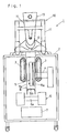
- the bagging and packaging machine 1 includes a base framework 2, a roll support (not shown) mounted on a rear top portion of the base framework 2 for rotatably supporting a roll of packaging material and a bag former 10 mounted on a front top portion of the base framework 2.
- the bag former 10 of a unitary structure includes a frame 11 on which a sailor member 12 and a tube member 13 extending vertically through the sailor member 12 are mounted (See particularly Fig. 2 ).
- This bag former 10 is detachably mounted on a front upper surface of the base framework 2 and is so designed and so structured that as a strip of packaging material drawn outwardly from the roll of the packaging material can be guided downwards, opposite longitudinal side edges of the strip of packaging material can be overlapped with each other.
- An upper portion 14 of the tube member 13 that protrudes upwards from the sailor member 12 is of a generally inverted conical shape having been upwardly flared to define a receiving opening into which articles to be bagged can be supplied from above.
- a lower portion 15 of the tube member 13 that protrudes downwards from the sailor member 12 is adapted to protrude into the packaging material, then formed into a tubular form, to supply the articles into the tubular packaging material.
- belt-type feeding devices 3 and 3 are disposed with their belts capable of running in a direction generally parallel to the direction of the feed of the tubular packaging material. These belt-type feeding devices 3 and 3 cooperate with the lower portion 15 of the tube member 13 so as to draw the tubular packaging material downwards in frictional contact with circumferentially opposite portions of the tubular packaging material that are then urged by the respective belts against correspondingly circumferentially opposite outer surface areas 15a and 15a of the lower portion 15 of the tube member 13.
- the overlapping side edges of the tubular packaging material that are so formed by the bag former 10 are, as the tubular packaging material is drawn downwards by the belt-type feeding devices 3 and 3 in the manner described above, fusion bonded together to form a longitudinally sealed tubular packaging material by means of a vertical sealing device 5 that is supported at the front of the base framework 2 by means of a support arm 4.
- a transverse sealing device 6 capable of performing a sequential process of clamping the tubular packaging material, of which overlapping side edges have been sealed by the longitudinal sealing unit 5, that is, the longitudinally sealed tubular packaging material from front and rear directions to fuse a predetermined position of the longitudinally sealed tubular packaging material in a transverse direction perpendicular to the direction of feed of the packaging material, cutting the predetermined position of the longitudinally sealed tubular packaging material in the transverse direction to thereby leave a bottom seal in the longitudinally sealed tubular packaging material above the transverse cut line, and forming, after the articles have been filled in a portion of the longitudinally sealed packaging material above the bottom seal, a top seal thereby leaving a bagged product.
- a delivery device 7 for transporting the bagged product towards the subsequent processing station out of the bagging and packaging machine 1 is disposed under the transverse sealing device 6.
- the bagging and packaging machine 1 is provided with a substitute gas supply passage 16 defined adjacent an inner surface of a front wall 15b of a tube member 13 for the supply of an inert gas into the article filled bag to substitute for the air within the article filled bag.
- the substitute gas supply passage 16 is formed by securing a generally elongated plate 19, shown in Fig. 9 , in spaced relation to the front wall 15b of the tube member 13 so as to extend generally vertically from the upper portion 14 of the tube member 13 down to the lower portion 15 thereof so as to leave a generally vertically elongated space between the elongated plate 19 and the front wall 15d of the tube member 13.
- the substitute gas passage 16 has an upper end closed by an upper end portion of the elongated plate 19 that is bent so as to extend towards a front wall of the upper portion 14 of the tube member 13 as shown in Fig. 2 .
- a portion of the front wall of the upper portion 14 of the tube member 13 adjacent the closed upper end of the substitute gas passage 16 has a gas supply port 17 defined therein in communication with the substitute gas supply passage 16, and a gas supply piping 25 (See Fig. 3 ) is fluid-connected with the gas supply port 17.
- the substitute gas supply passage 16 has a lower end left open to thereby define a gas outlet 18.
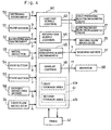
- the bagging and packaging machine 1 also includes a gas supply unit 20 positioned external to the machine 1 for supplying the substitute gas, which may be an inert gas such as, for example, a nitrogen or argon gas, therefrom into the substitute gas passage 16 as shown in Fig. 3 .
- the substitute gas which may be an inert gas such as, for example, a nitrogen or argon gas
- the gas supply unit 20 includes a nitrogen gas supply tank 21 containing a quantity of the inert gas, for example, nitrogen gas, a valve 22 for supplying the nitrogen gas downstream from the supply tank 21, a filter 23 for removing impurities contained in the nitrogen gas being supplied, and a first flow regulator 24 for controlling the flow of the nitrogen gas supplied through the filter 23 and also for measuring the flow rate of the nitrogen gas by a flow meter.
- the nitrogen gas supplied from the nitrogen gas supply tank 21 through the valve 22 is, after having passed through the filter 23 where the impurities are removed from the nitrogen gas, regulated by the first flow regulator 24 to a predetermined flow rate before the nitrogen gas is further supplied downstream.
- the gas supply tank 21 is fluid connected through a supply pipe 25 with the valve 22 which is in turn fluid connected through a supply pipe 25 with the filter 23 which is also in turn fluid connected through a supply pipe 25 with the first flow regulator 24.
- a supply pipe 25 fluid connected with the first flow regulator 24 and extending downstream with respect to the direction of supply of the substitute gas is shunt to a high pressure supply pipe 25a, a low pressure supply pipe 25b and a blow-off supply pipe 25c.
- the high pressure supply pipe 25a and the low pressure supply pipe 25b are merged together to define a supply pipe 25ab that is fluid connected with the gas supply port 17 defined in the substitute gas passage 16.
- the blow-off supply pipe 25c has a downstream end fluid disposed within an upper open end of the tube member 13 so as to introduce the nitrogen gas into the interior of the tube member 13 as shown in Fig. 2 .
- a high pressure electromagnetic valve 26 is disposed on the high pressure supply pipe 25a for selectively initiating or interrupting the flow therethrough of the nitrogen gas supplied from the nitrogen gas supply tank 21.
- a low pressure electromagnetic valve 27 similar to the high pressure electromagnetic valve 26 is disposed on the low pressure supply pipe 25b. Selective energization or deenergization of each of those electromagnetic valves 26 and 27 is controlled by a first gas supply control means 43. It is to be noted that the low pressure electromagnetic valve 27 has its downstream side fluid connected with a second flow regulator 28 for controlling the flow rate of the nitrogen gas delivered from the low pressure electromagnetic valve 27, which second flow regulator 28 is equipped with a flow meter for measuring the flow rate of the nitrogen gas.
- Adjustment of the flow rate of the nitrogen gas that is accomplished by the second flow regulator 28 is carried out by a second gas supply control means 44 on the basis of the oxygen remaining rate as will be described in detail later.
- a blow-off electromagnetic valve 29 similar to any one of the high pressure electromagnetic valve 26 and the low pressure electromagnetic valve 27 is similarly disposed on the supply pipe 25c and that by controlling selective energization and deenergization of the blow-off electromagnetic valve 29, the nitrogen gas can be supplemented from the upper open end of the upper portion 14 of the tube member 13 into the interior of the tube member 13.
- the bagging and packaging machine 1 is provided with a control unit 40 including a memory device 41 built therein.
- This memory device 41 has a first storage area 41a in which the necessary oxygen remaining rate coordinated with properties of the bagged product is stored for each kind of the bagged products.
- the memory device 41 also has a second storage area 41b in which the current status of supply of the nitrogen gas and the oxygen remaining rate during operation of the bagging and packaging machine 1 can be stored.
- the control unit 40 also includes, in addition to the first gas supply control means 43 and the second gas supply control means 44 both shown in Fig. 3 , an oxygen remaining rate determining means 45 and a display control means 46 both as will be described in detail later.
- the first gas supply control means 43 Based on time, a temporary interruption signal or a halt signal, the first gas supply control means 43 outputs control signals i and j, used to control opening and closure of the high pressure electromagnetic valve 26 and the low pressure electromagnetic valve 27, respectively, to such electromagnetic valves 26 and 27.
- the second gas supply control means 44 outputs a signal to the second flow regulator 28 to regulate the flow rate of the nitrogen gas.
- the control unit 40 is adapted to receive the temporary interruption signal used to temporarily interrupt activation of the bagging and packaging machine 1 and the halt signal used to halt the activation of the bagging and packaging machine 1. It is, however, to be noted that the bagging and packaging machine 1 once interrupted temporarily can resume its normal operation when a factor for which the bagging and packaging machine is interrupted temporarily is removed, but the bagging and packaging machine 1 once halted will not resume its normal operation unless the attendant worker performs a starting procedure, that is, activate the bagging and packaging machine 1.
- the temporary interruption signal includes an insufficient article signal a generated from a metering instrument 50 in the event that the article to be filled in each of the successively formed bags is short of a predetermined quantity or weight, a gas flow reduction signal b generated from a flow rate sensor 51 for detecting the flow rate of the nitrogen gas supplied from the nitrogen gas supply tank 21 in the event that the flow rate of the nitrogen gas decreases, a temporary interruption signal c generated from a downstream instrument 52 disposed downstream of the bagging and packaging machine 1, and others.
- the halt signal includes a halt signal c' generated from the downstream instrument 52, a metal detection signal d generated from a metal detector 53 in the event that the metal detector 53 detects the presence of one or more metallic particles contained in the bagged product, a halt signal e generated from a stop button 54 manipulated by the attendant worker, and others.
- the control unit 40 are also adapted to receive, other than the temporary interruption signal and the halt signal both discussed above, a start signal f generated from a start button 55 manipulated by the attendant worker when the bagging and packaging machine 1 is desired to be activated, a detection signal g generated from an oxygen detecting sensor 56 for detecting the amount of oxygen contained within each of the successively formed bags, a flow signal h generated from the flow meter built in the first flow regulator 24, and others.
- a timer 42 provided external to the control unit 40 starts counting the length of time passing. Based on the length of time counted by the timer 42, the first gas supply control means 43 of the control unit 40 generates the control signals i and j to the high pressure electromagnetic valve 26 and the low pressure electromagnetic valve 27, respectively so that the electromagnetic valves can be selectively switched on and off in response to the associated control signals i and j.
- the second gas supply control means 44 of the control unit 40 also generates, in response to the detection signal g, a control signal with which the low pressure electromagnetic valve 27 can be finely adjusted.
- the oxygen remaining rate determining means 45 of the control unit 40 issues a warning signal k to a warning device 57 to cause the warning device 57 to generate a warning.
- the attendant worker can readily be acknowledged of the oxygen remaining rate then increasing and can, therefore, attend to dealing with the incident. Accordingly, it is possible to prevent the bagging and packaging machine 1 to continue production of the bagged products having an increased oxygen remaining rate.
- the display control means 46 of the control unit 40 generates to a monitor display 58 a display signal m indicative of the operating condition of the bagging and packaging machine 1 and the condition of supply of the nitrogen gas from the gas supply unit 20 so that these conditions can be displayed through the monitor display 58.
- the monitor display 58 the attendant worker can come to know of the condition of supply of the nitrogen gas towards the bagging and packaging machine 1.
- the condition of supply of the nitrogen gas may be represented by, for example, the amount of the nitrogen gas remaining within the nitrogen gas supply tank 21.
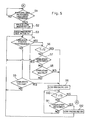
- the control unit 40 makes a decision of whether or not the bagging and packaging machine 1 is electrically powered on to run.
- This step S 1 is repeated before the bagging and packaging machine 1 is powered on and, only when the bagging and packaging machine 1 is powered on to run, the first gas supply control means 43 of the control unit 40 causes the high pressure electromagnetic valve 26 and the low pressure electromagnetic valve 27 to be turned on at step S2 and at the same time the timer 42 is started.
- the nitrogen gas supplied from the nitrogen gas supply tank 21 is adjusted by the first flow regulator 24 to a predetermined gas flow rate which is in turn supplied to the gas supply port 17 defined in the substitute gas passage 16 through the high pressure electromagnetic valve 26 and the low pressure electromagnetic valve 27.
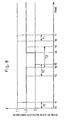
- the flow rate of the nitrogen gas supplied to the gas supply port 17 is adjusted to a high pressure flow rate L1 (See Figs. 6 to 8 ).
- the first gas supply control means 43 of the control unit 40 switches the high pressure electromagnetic valve 26 off at step S3.
- the nitrogen gas supplied to the gas supply port 17 defined in the substitute gas supply passage 16 is adjusted by the second flow regulator 28 through the low pressure electromagnetic valve 27 to a low pressure flow rate L2 (See Figs. 6 to 8 ) and is then supplied to the gas supply port 17.
- L2 See Figs. 6 to 8
- the nitrogen gas in the low pressure flow rate L2 is supplied into the bag into which the article is introduced.
- the length of time counted by the timer 42 once it has attained the high pressure gas supply time T1 is reset by the first gas supply control means 43.
- step S 4 the first gas supply control means 43 of the control unit 40 makes a decision of whether or not the temporary interruption signal is inputted to the control unit 40.
- the program flow goes to step S5 at which a decision is made to determine whether or not the halt signal is inputted to the control unit 40. Where no halt signal is inputted to the control unit 40, the program flow returns to step S4.
- the first gas supply control means 43 determines whether or not the length of time T has exceeded the low pressure gas supply time T2 which has been preset.
- the first gas supply control means 43 determines at step S7 whether or not the inputting of the temporary interruption signal to the control unit 40 is released. In the event that the inputting of the temporary interruption signal is not released, the first gas supply control means 43 again determines at step S8 whether or not the halt signal is inputted to the control unit 40. In the event that no halt signal is inputted to the control unit 40, the program flow returns to step S6.
- step S7 the timer 42 is reset by the first gas supply control means 43 and the program flow returns to step S4.
- the low pressure electromagnetic valve 27 is held in an ON state before the length of time T counted by the timer 42 exceeds the predetermined low pressure gas supply time T2 and, consequently, the nitrogen gas continues to be supplied at the flow rate L2 to the bagging and packaging machine 1.
- the first gas supply control means 43 of the control unit 40 switches the low pressure electromagnetic valve 27 off at step S9. Hence, the supply of the nitrogen gas to the bagging and packaging machine 1 is completely halted.
- step S10 the first gas supply control means 43 determines whether or not the length of time T' exceeds the predetermined low pressure gas supply wait time T3. Should the length of time T' have exceeded the predetermined low pressure gas supply wait time T3, the program flow returns to step S1, but should it have not exceeded the predetermined low pressure gas supply wait time T3, the program flow goes to step S11 at which the first gas supply control means 43 determines whether or not the bagging and packaging machine 1 is re-started.
- the program flow returns to step S10, but in the event that the bagging and packaging machine 1 has been activated, the first gas supply control means 43 of the control unit 40 switches the low pressure electromagnetic valve 27 on at step S12, thereby repeating the program flow from step S4 onwards. As a result, the nitrogen gas is again supplied at the flow rate L2 to the bagging and packaging machine 1.
- the timer 42 starts counting the length of time and, at the same time, the high pressure electromagnetic valve 26 and the low pressure electromagnetic valve 27 are switched on, allowing the nitrogen gas to be supplied under a high pressure at the flow rate L1 to the gas supply port 17 disposed in the substitute gas passage 16.
- the timer 42 is reset and, at the same time, the high pressure electromagnetic valve 26 is switched off, thereby allowing the nitrogen gas, supplied to the gas supply port 17 in the substitute gas passage 16, to flow through the second flow regulator 28 by way of the low pressure electromagnetic valve 27.
- the nitrogen gas emerging from the second flow regulator is supplied under a low pressure at the flow rate L2 towards the gas supply port 17 and then into the bag filled with the article.
- the timer 42 starts counting the length of time passing from the timing t2 at which the machine 1 is temporarily brought to a halt, but the supply of the nitrogen gas continues at the low pressure flow rate L2 to the bagging and packaging machine 1.
- the bagging and packaging machine once halted temporarily resumes its operation by the automatic stop timing t3 that occurs the low pressure gas supply time T2 after the temporarily halted timing t2, the timer 42 is reset at the timing ta at which the temporary halt of the bagging and packaging machine 1 is released, and the supply of the nitrogen gas continues at the low pressure flow rate L2 to the bagging and packaging machine 1.
- the timer 42 starts counting the length of time at the timing the bagging and packaging machine 1 is brought to a halt, that is, the timing t4 at which the supply of the nitrogen gas is interrupted, and the low pressure electromagnetic valve 27 is switched off at the gas supply interrupting timing t4. In other words, the supply of the nitrogen gas to the bagging and packaging machine 1 is completely interrupted.
- the timer 42 is reset and the low pressure electromagnetic valve 27 is switched on at the low pressure gas supply resuming timing tb.
- the nitrogen gas is again supplied under the low pressure at the flow rate L2 to the bagging and packaging machine 1.
- the reason for the supply of the nitrogen gas under the high pressure at the flow rate L1 to the bagging and packaging machine 1 in this manner is because if the bagging and packaging machine 1 is started at the timing past the low pressure gas supply resuming timing t5, the replacement rate of the gas within the bag is lowered and, therefore, a relatively large quantity of the nitrogen gas has to be supplied into the bag.
- Fig. 7 when the bagging and packaging machine is activated, that is, at the timing t0 at which the supply of the nitrogen gas under high pressure is initiated, the timer 42 starts counting the length of time and, at the same time, the high pressure electromagnetic valve 26 and the low pressure electromagnetic valve 27 are switched on to allow the nitrogen gas to be supplied under a high pressure at the flow rate L1 to the gas supply port 17 in the substitute gas passage 16.
- the timer 42 When the count of the timer 42 subsequently attains the length of time T1, that is, at the timing tl at which the high pressure gas supply is halted, the timer 42 is reset and, at the same time, the high pressure electromagnetic valve 26 is switched off, thereby allowing the nitrogen gas, supplied to the gas supply port 17 in the substitute gas passage 16, to flow through the second flow regulator 28 by way of the low pressure electromagnetic valve 27.
- the nitrogen gas emerging from the second flow regulator is supplied under a low pressure at the flow rate L2 towards the gas supply port 17 and then into the bag filled with the article.
- the timer 42 starts counting the length of time passing from the timing t2 at which the machine 1 is temporarily brought to a halt, but the supply of the nitrogen gas continues at the low pressure flow rate L2 to the bagging and packaging machine 1.
- the bagging and packaging machine is automatically halted at the automatic stop timing t3 that occurs the low pressure gas supply time T2 after the temporarily halted timing t2 and, at the same time, the timer 42 is reset.
- the timer 42 starts counting the length of time from the gas supply interrupting timing t4 which is the same timing as the timing at which the bagging and packaging machine 1 is halted, that is, the automatic stop timing t3 and, at the timing t4, the low pressure electromagnetic valve 27 is switched off.
- the supply of the nitrogen gas to the bagging and packaging machine 1 is completely interrupted.
- the nitrogen gas can be supplied under a high pressure at the flow rate L1 to the bagging and packaging machine 1 as shown by the phantom line.
- Fig. 8 when the bagging and packaging machine is activated, that is, at the high pressure gas supply start timing t0, the timer 42 starts counting the length of time and, at the same time, the high pressure electromagnetic valve 26 and the low pressure electromagnetic valve 27 are switched on to allow the nitrogen gas to be supplied under a high pressure at the flow rate L1 to the gas supply port 17 in the substitute gas passage 16.
- the timer 42 When the count of the timer 42 subsequently attains the length of time T1, that is, at the high pressure gas supply interruption timing t1, the timer 42 is reset and, at the same time, the high pressure electromagnetic valve 26 is switched off, thereby allowing the nitrogen gas, supplied to the gas supply port 17 in the substitute gas passage 16, to flow through the second flow regulator 28 by way of the low pressure electromagnetic valve 27. Hence, the nitrogen gas emerging from the second flow regulator is supplied under a low pressure at the flow rate L2 towards the gas supply port 17 and then into the bag filled with the article.
- the timer 42 starts counting the length of time passing from the timing t2 at which the machine 1 is temporarily brought to a halt, but the supply of the nitrogen gas continues at the low pressure flow rate L2 to the bagging and packaging machine 1.
- the bagging and packaging machine is automatically halted before the automatic stop timing t3 that occurs the low pressure gas supply time T2 after the temporarily halted timing t2
- the timer 42 is reset and starts counting the length of time, and at the gas supply interrupting timing t4 the low pressure electromagnetic valve 27 is switched off.
- the supply of the nitrogen gas to the bagging and packaging machine 1 is completely interrupted.
- the nitrogen gas can be supplied under a high pressure at the flow rate L1 to the bagging and packaging machine 1 as shown by the phantom line.
- the bagging and packaging machine 1 is electrically powered, and the strip of bag material is drawn forwards from the roll support disposed at the rear of the base framework 2 so as to travel downwards from a front upper portion of the base framework 2 so that the opposite longitudinal side edges of the strip of bag material can be turned to overlap one above the other by means of the sailor member 12 forming a part of the bag former 10 with that portion of the strip of bag material consequently shaped into a tubular form.
- the overlapped longitudinal side edges of the tubular strip of bag material is sealed by the longitudinal sealing unit 5 at a location adjacent an outer surface of the front wall of the lower portion 15 of the tube member 13, thereby forming a bag C ( Fig. 9 ).
- a lower portion of the tubular strip of bag material was sealed by a transverse sealing device 6 during the previous cycle of bag forming operation.
- articles X ⁇ X are filled into the bag C from above through the tube member 13.
- the nitrogen gas is supplied into the bag C from the gas supply means 20 through the substitute gas passage 16 to substitute for the air within the bag C, which air is purged to the outside through the upper end of the tube member 13 and an open bent portion of the tubular strip of bag material formed by the sailor member 12. In this way, the air within the bag filled with the articles X ⁇ X is replace with the nitrogen gas.
- the stored oxygen remaining rate is read out from the first storage area 41 a of the memory device 41 and is used by the second gas supply control means 44 to supply the nitrogen gas from the gas supply unit 20 in a quantity sufficient to allow the oxygen remaining rate within the bag C to attain a value generally or substantially equal to the stored oxygen remaining rate.
- An example of the control of the supply of the nitrogen gas based on the oxygen remaining rate is shown by the chain line in Fig. 6 . This control is finely adjusted with reference to the nitrogen gas flow rate L2 taken as a reference.
- the supply of the nitrogen gas from the gas supply unit 20 into each of the successively formed bags C is thus controlled. Specifically, at the start of the bagging and packaging operation performed by the bagging and packaging machine 1, the nitrogen gas supplied from the gas supply unit 20 is supplied at the high pressure flow rate L1 into each bag C. At this time, to avoid any possible blow-up of some of the articles X ⁇ X within the respective bag C, no articles is introduced into the bag C during a period in which the nitrogen gas is supplied at the high pressure flow rate L1.
- the flow rate of the nitrogen gas is adjusted from the high pressure flow rate L I to the low pressure flow rate L2 and, at the same time, the articles X ⁇ X are introduced into the bag C.
- the low pressure flow rate L2 is of a value so chosen and so adjusted that no blow-up of the articles X ⁇ X will, substantially occur within the bag. Even so, a relatively high gas replacement rate can be attained.
- the low pressure flow rate L2 is, however, set depending on the weight and the shape of the bag and is of a value appropriate to the type or kind of the articles to be bagged.
- the bag with the articles X ⁇ X filled therein is heat-sealed by a pair of bar members 6a and 6a of the transverse sealing device 6 at an upstream location above the filled articles X ⁇ X within the bag C and is then separated from the strip of bag material.
- the bag C with the articles X ⁇ X filled therein is subsequently falls onto the delivery device 7. It is to be noted that the upstream portion of the bag C with the articles X ⁇ X filled therein that is cut to separate the filled bag C from the strip of bag material defines a bottom seal for the subsequently formed bag in readiness for the subsequent filling of the articles thereinto.
- the bagged products each comprised of a bag having a predetermined quantity of articles filled therein and also with the inert gas filled therein are successively manufactured and are delivered out of the bagging and packaging machine 1 through the delivery device 7.
- the gas supply unit 20 continues supplying the nitrogen gas under low pressure at the flow rate L2 into the bag C for a predetermined length of time. Accordingly, since the oxygen remaining rate within the bag C is not increased when the bagging and packaging machine 1 resumes its normal operation within the predetermined length of time, the bagged products each having the oxygen remaining rate controlled down to a predetermined value can be obtained with no need to interrupt the bagging and packaging operation.
- the bagging and packaging machine 1 is brought to a halt and the gas supply unit 20 completely interrupts the supply of the nitrogen gas towards the bagging and packaging machine 1. Accordingly, the amount of the gas supplied from the gas supply unit 20 will not increase unnecessarily.
- the nitrogen gas can be again supplied under low pressure at the flow rate L2 into the bag C. Accordingly, not only can the amount of the gas supplied from the gas supplied unit 20 be suppressed advantageously, but the bagged products each having the oxygen remaining rate controlled down to a predetermined value can be obtained.
Landscapes
- Engineering & Computer Science (AREA)
- Mechanical Engineering (AREA)
- Chemical & Material Sciences (AREA)
- Dispersion Chemistry (AREA)
- Vacuum Packaging (AREA)
Claims (4)
- Machine d'ensachage et de conditionnement pour former un sachet à partir d'une bande de tissu à sachet et introduire un article dans le sachet, ladite machine d'ensachage et de conditionnement comprenant :un moyen d'alimentation de gaz pour alimenter un gaz inerte dans le sachet afin de remplacer l'air contenu dans le sachet ; etun moyen de commande d'alimentation de gaz pour commander l'alimentation du gaz inerte par le moyen d'alimentation de gaz dans le sachet ; caractérisée en ce que :ledit moyen de commande d'alimentation de gaz est exploitable pour effectuer l'alimentation du gaz inerte dans le sachet à un premier débit d'écoulement pendant une durée prédéterminée suite au début de l'opération de la machine d'ensachage et de conditionnement afin de parvenir ainsi à un taux de remplacement de gaz élevé et pour régler l'alimentation du gaz inerte à un second taux d'écoulement inférieur au premier débit d'écoulement au terme de la durée prédéterminée, avant d'introduire l'article dans le sachet de telle sorte que le gaz inerte soit alimenté au second débit d'écoulement dans une opération d'ensachage et de conditionnement.
- Machine d'ensachage et de conditionnement selon la revendication 1, dans laquelle le moyen de commande d'alimentation de gaz commande au moyen d'alimentation de gaz de continuer d'alimenter le gaz inerte dans le sachet au second débit d'écoulement pendant une seconde durée prédéterminée après une halte temporaire de la machine d'ensachage et de conditionnement, et d'interrompre l'alimentation du gaz inerte au terme de la seconde durée prédéterminée.
- Machine d'ensachage et de conditionnement selon l'une quelconque des revendications précédentes, comprenant en outre un moyen d'affichage pour fournir une indication visuelle d'un état d'alimentation du gaz inerte depuis le moyen d'alimentation de gaz.
- Machine d'ensachage et de conditionnement selon l'une quelconque des revendications précédentes, comprenant en outre un moyen de mémoire de données électronique pour mémoriser un état d'alimentation du gaz inerte depuis le moyen d'alimentation de gaz durant le fonctionnement de la machine d'ensachage et de conditionnement.
Priority Applications (1)
| Application Number | Priority Date | Filing Date | Title |
|---|---|---|---|
| EP08160277A EP2022720A3 (fr) | 1999-12-27 | 2000-12-21 | Machine de mise en sachet et de conditionnement capable d'introduire un volume adéquat de gaz inerte dans les sachets |
Applications Claiming Priority (2)
| Application Number | Priority Date | Filing Date | Title |
|---|---|---|---|
| JP37007299A JP4408510B2 (ja) | 1999-12-27 | 1999-12-27 | 製袋包装機 |
| JP37007299 | 1999-12-27 |
Related Child Applications (2)
| Application Number | Title | Priority Date | Filing Date |
|---|---|---|---|
| EP08160277A Division EP2022720A3 (fr) | 1999-12-27 | 2000-12-21 | Machine de mise en sachet et de conditionnement capable d'introduire un volume adéquat de gaz inerte dans les sachets |
| EP08160277.3 Division-Into | 2008-07-11 |
Publications (2)
| Publication Number | Publication Date |
|---|---|
| EP1112936A1 EP1112936A1 (fr) | 2001-07-04 |
| EP1112936B1 true EP1112936B1 (fr) | 2013-05-15 |
Family
ID=18496009
Family Applications (2)
| Application Number | Title | Priority Date | Filing Date |
|---|---|---|---|
| EP08160277A Withdrawn EP2022720A3 (fr) | 1999-12-27 | 2000-12-21 | Machine de mise en sachet et de conditionnement capable d'introduire un volume adéquat de gaz inerte dans les sachets |
| EP00311558.1A Expired - Lifetime EP1112936B1 (fr) | 1999-12-27 | 2000-12-21 | Machine d'ensachage pour le remplissage des sacs avec une quantité suffisante d'un gaz inerte |
Family Applications Before (1)
| Application Number | Title | Priority Date | Filing Date |
|---|---|---|---|
| EP08160277A Withdrawn EP2022720A3 (fr) | 1999-12-27 | 2000-12-21 | Machine de mise en sachet et de conditionnement capable d'introduire un volume adéquat de gaz inerte dans les sachets |
Country Status (3)
| Country | Link |
|---|---|
| US (1) | US6735928B2 (fr) |
| EP (2) | EP2022720A3 (fr) |
| JP (1) | JP4408510B2 (fr) |
Cited By (1)
| Publication number | Priority date | Publication date | Assignee | Title |
|---|---|---|---|---|
| US8808325B2 (en) | 2006-09-29 | 2014-08-19 | Ethicon Endo-Surgery, Inc. | Surgical stapling instrument with staples having crown features for increasing formed staple footprint |
Families Citing this family (32)
| Publication number | Priority date | Publication date | Assignee | Title |
|---|---|---|---|---|
| JP4408510B2 (ja) * | 1999-12-27 | 2010-02-03 | 株式会社イシダ | 製袋包装機 |
| JPWO2004011334A1 (ja) * | 2002-07-30 | 2005-11-24 | 株式会社イシダ | 包装機、包装方法、および包装システム |
| US20040084087A1 (en) * | 2002-10-30 | 2004-05-06 | Sanfilippo John E. | Apparatus and method for controlling and distributing gas flow |
| MXPA04012837A (es) * | 2004-01-06 | 2005-07-07 | Tna Australia Pty Ltd | Maquina empaquetadora y conformador. |
| JP2005239181A (ja) * | 2004-02-25 | 2005-09-08 | Ishida Co Ltd | 縦型製袋包装機 |
| JP4427353B2 (ja) * | 2004-02-26 | 2010-03-03 | 株式会社イシダ | 包装機 |
| KR100865512B1 (ko) * | 2004-04-30 | 2008-10-27 | 오리히로엔지니어링가부시끼가이샤 | 종형(縱型) 충전 포장기 |
| US7198206B2 (en) * | 2004-08-02 | 2007-04-03 | Clear Lam, Inc. | Compact gassing lance |
| ITBO20040534A1 (it) * | 2004-08-26 | 2004-11-26 | Gino Rapparini | Processo per il confezionamento asettico di liquidi sterli in contenitori flessibili |
| US20060213153A1 (en) * | 2005-03-03 | 2006-09-28 | Sanfilippo James J | Device and system for modified atmosphere packaging |
| CA2621769C (fr) * | 2005-09-07 | 2013-04-30 | General Packer Co., Ltd. | Procede permettant d'introduire un gaz inerte dans une machine d'emballage a remplissage de gaz |
| BRPI0712187A2 (pt) * | 2006-06-05 | 2012-03-06 | Liqui-Box Canada Inc. | processo e aparelho para formar uma bolsa de espaÇo confinado mÍnimo |
| US7581427B2 (en) * | 2006-11-14 | 2009-09-01 | Mocon, Inc. | Workspace analyte sensing system and method using a fan to move samples from the workspace to the sensor |
| US9266630B2 (en) * | 2009-02-25 | 2016-02-23 | Liqui-Box Corporation | Process for pouch forming with optimized fill-accuracy and headspace |
| US9718569B2 (en) * | 2009-04-13 | 2017-08-01 | Kraft Foods Group Brands Llc | Modified atmospheric flow-wrap system |
| US8371094B2 (en) * | 2009-10-23 | 2013-02-12 | Frito-Lay North America, Inc. | Method and apparatus for compacting product |
| US8567165B2 (en) * | 2009-10-23 | 2013-10-29 | Frito-Lay North America, Inc. | Method and apparatus for compacting product |
| US8656690B2 (en) * | 2009-10-23 | 2014-02-25 | Frito-Lay North America, Inc. | Method and apparatus for compacting product |
| US9284075B2 (en) | 2009-10-23 | 2016-03-15 | Frito-Lay North America, Inc. | Apparatus for compacting product and high speed bagmaking |
| CN102686483B (zh) * | 2009-12-18 | 2014-06-11 | 利乐拉瓦尔集团及财务有限公司 | 灌装组件与用于该灌装组件的垫片以及灌装液体的方法 |
| ITMI20120388A1 (it) * | 2011-03-17 | 2012-09-18 | Tna Australia Pty Ltd | Dispositivo di formatura per confezionatrice |
| MX365300B (es) | 2011-05-04 | 2019-05-29 | Dole Fresh Vegetables Inc | Sistema de barrido de gas de alto flujo, baja velocidad para reducir y verificar el contenido de oxigeno en contenedores de produccion empacados. |
| JP5882155B2 (ja) * | 2012-07-23 | 2016-03-09 | 株式会社イシダ | 包装装置 |
| DE102013004292B4 (de) * | 2013-03-13 | 2015-07-09 | Witt Gmbh & Co. Holding Und Handels-Kg | Messvorrichtung für Schlauchbeutelverpackungsmaschinen |
| US10494125B2 (en) * | 2013-06-04 | 2019-12-03 | Tetra Laval Holdings & Finance S.A. | Device and method in a filling machine |
| WO2016022792A2 (fr) * | 2014-08-07 | 2016-02-11 | Plank Road Technologies, Llc | Système et procédé permettant de prévenir et de maîtriser la combustion et l'inflammabilité ou l'oxydation de matériaux pendant leur stockage ou leur transport |
| JP2016055878A (ja) * | 2014-09-05 | 2016-04-21 | 東洋自動機株式会社 | 気体流路付き袋並びに袋の包装方法及び装置 |
| CN105691707A (zh) * | 2016-03-23 | 2016-06-22 | 张春生 | 一种多功能自动包装机 |
| NL2018335B1 (en) * | 2017-02-08 | 2018-09-03 | Perfo Tec B V | Method and apparatus for packaging respiring produce |
| GB2560717A (en) | 2017-03-20 | 2018-09-26 | Plumat Plate & Lubeck Gmbh & Co | A method and apparatus for manufacturing a double bag |
| JP7726522B2 (ja) * | 2021-10-27 | 2025-08-20 | ゼネラルパッカー株式会社 | 包装容器内の酸素濃度制御方法および包装機 |
| EP4350202A1 (fr) * | 2022-10-05 | 2024-04-10 | Sealed Air Corporation (US) | Dispositif d'alimentation en gaz pour une machine d'emballage et système de fabrication d'emballages et procédé utilisant ledit système |
Family Cites Families (22)
| Publication number | Priority date | Publication date | Assignee | Title |
|---|---|---|---|---|
| US3482373A (en) * | 1967-11-06 | 1969-12-09 | Packaging Frontiers Inc | Packaging |
| DE1786137C3 (de) * | 1968-08-22 | 1974-01-03 | Fr. Hesser Maschinenfabrik Ag, 7000 Stuttgart | Schlauchbeutelfüllmaschine mit einem der Schlauchbildung dienenden Formrohr und einem vom Formrohr umgeschlossenen Füllrohr |
| US3789888A (en) * | 1969-12-29 | 1974-02-05 | Hayssen Mfg Co | Gas flushing system for vertical form, fill and seal machines |
| US3664086A (en) * | 1969-12-29 | 1972-05-23 | Hayssen Mfg Co | Gas flushing system for vertical form, fill and seal machines |
| CH533537A (de) * | 1970-12-21 | 1973-02-15 | Gericke & Co | Vorrichtung zum Abfüllen eines Behältnisses mit verdichtetem, pulvrigem Gut |
| US3948015A (en) * | 1971-05-03 | 1976-04-06 | Automated Packaging Systems, Inc. | Packaging system |
| DE2261978A1 (de) * | 1972-12-18 | 1974-06-20 | Hesser Ag Maschf | Vorrichtung zum sauerstofffreispuelen von abzumessenden und zu verpackenden schuettguetern |
| DE2503547A1 (de) * | 1975-01-29 | 1976-08-05 | Jentsch Hans G | Verfahren und vorrichtung zum sterilen abfuellen von fluessigem, pulverfoermigem, granuloesem oder koernigem fuellgut in behaelter bzw. beutel aus siegelfaehigem material |
| US4636391A (en) * | 1985-08-22 | 1987-01-13 | Patrick J. Furlong | Apparatus and method of forming a sterile product package |
| US4769974A (en) * | 1987-07-30 | 1988-09-13 | W. A. Lane, Inc. | Process and apparatus for gas purging of a bag being formed, filled and sealed on a bagging machine |
| US4964259A (en) * | 1989-08-02 | 1990-10-23 | Borden, Inc. | Form-fill-seal deflation method and apparatus |
| US5060514A (en) * | 1989-11-30 | 1991-10-29 | Puritan-Bennett Corporate | Ultrasonic gas measuring device |
| US5201165A (en) * | 1990-10-05 | 1993-04-13 | International Paper Company | Gas displacement device for packaging food and non-food products |
| IT1272511B (it) * | 1993-08-11 | 1997-06-23 | Luigi Goglio | Procedimento ed impianto per l'imballaggio del caffe' |
| US6032438A (en) * | 1993-09-16 | 2000-03-07 | Sanfilippo; James J. | Apparatus and method for replacing environment within containers with a controlled environment |
| US5678388A (en) * | 1995-06-07 | 1997-10-21 | Southpac Trust International, Inc. | Apparatus and method for making and bagging decorative grass |
| JPH1053217A (ja) * | 1996-08-09 | 1998-02-24 | Calbee Foods Co Ltd | 袋詰め装置及びその方法 |
| US5961000A (en) * | 1996-11-14 | 1999-10-05 | Sanfilippo; James J. | System and method for filling and sealing containers in controlled environments |
| US5822951A (en) * | 1997-11-06 | 1998-10-20 | Modern Controls, Inc. | Apparatus and method for sampling gas in product packages |
| DE19840857A1 (de) * | 1998-09-08 | 2000-03-09 | Rovema Gmbh | Verpackungsvorrichtung |
| US6202388B1 (en) * | 1998-11-06 | 2001-03-20 | Jescorp, Inc. | Controlled environment sealing apparatus and method |
| JP4408510B2 (ja) * | 1999-12-27 | 2010-02-03 | 株式会社イシダ | 製袋包装機 |
-
1999
- 1999-12-27 JP JP37007299A patent/JP4408510B2/ja not_active Expired - Fee Related
-
2000
- 2000-12-21 EP EP08160277A patent/EP2022720A3/fr not_active Withdrawn
- 2000-12-21 EP EP00311558.1A patent/EP1112936B1/fr not_active Expired - Lifetime
- 2000-12-27 US US09/748,907 patent/US6735928B2/en not_active Expired - Lifetime
Cited By (1)
| Publication number | Priority date | Publication date | Assignee | Title |
|---|---|---|---|---|
| US8808325B2 (en) | 2006-09-29 | 2014-08-19 | Ethicon Endo-Surgery, Inc. | Surgical stapling instrument with staples having crown features for increasing formed staple footprint |
Also Published As
| Publication number | Publication date |
|---|---|
| JP2001180614A (ja) | 2001-07-03 |
| EP1112936A1 (fr) | 2001-07-04 |
| US20010005974A1 (en) | 2001-07-05 |
| EP2022720A3 (fr) | 2009-04-08 |
| EP2022720A2 (fr) | 2009-02-11 |
| JP4408510B2 (ja) | 2010-02-03 |
| US6735928B2 (en) | 2004-05-18 |
Similar Documents
| Publication | Publication Date | Title |
|---|---|---|
| EP1112936B1 (fr) | Machine d'ensachage pour le remplissage des sacs avec une quantité suffisante d'un gaz inerte | |
| US8938936B2 (en) | Method and device for dosing and packaging polysilicon chunks and dosing and packaging unit | |
| EP1050460B1 (fr) | Système d'emballage avec un flux d'articles amélioré | |
| JP5015000B2 (ja) | 袋持上げ装置を備えた袋の形成、充填及び閉鎖機械 | |
| EP1077176B1 (fr) | Machine de remplissage pouvant remplir une quantité suffisante d'un gaz inerte dans des sacs | |
| CA2657129C (fr) | Procede et appareil de realisation d'un fil fourre | |
| JP2000238709A (ja) | 縦形製袋充填包装機の縦シール制御装置 | |
| US7143569B2 (en) | Calibrated shrink wrap packaging system and associated method | |
| US20060213153A1 (en) | Device and system for modified atmosphere packaging | |
| JP4514083B2 (ja) | 製袋包装機 | |
| CN206704573U (zh) | 一种用于氯化钾装料的吨包机 | |
| JP4312868B2 (ja) | 包装計量システム | |
| JP2002053104A (ja) | 横型製袋充填装置 | |
| EP2143644A1 (fr) | Equipement à plaquettes | |
| CN219750280U (zh) | 一种用于包装机的称重检测剔除装置以及包装机 | |
| JP7705134B2 (ja) | 製袋包装機 | |
| JP2008133030A (ja) | 包装装置 | |
| JPH01153437A (ja) | 小袋自動投入機の切断方法 | |
| JP5882155B2 (ja) | 包装装置 | |
| JP2024117617A (ja) | 製袋包装機 | |
| JPH03272908A (ja) | 棒状物品の整列収納装置 |
Legal Events
| Date | Code | Title | Description |
|---|---|---|---|
| PUAI | Public reference made under article 153(3) epc to a published international application that has entered the european phase |
Free format text: ORIGINAL CODE: 0009012 |
|
| AK | Designated contracting states |
Kind code of ref document: A1 Designated state(s): DE FR GB IT |
|
| AX | Request for extension of the european patent |
Free format text: AL;LT;LV;MK;RO;SI |
|
| 17P | Request for examination filed |
Effective date: 20011217 |
|
| AKX | Designation fees paid |
Free format text: DE FR GB IT |
|
| 17Q | First examination report despatched |
Effective date: 20080311 |
|
| GRAJ | Information related to disapproval of communication of intention to grant by the applicant or resumption of examination proceedings by the epo deleted |
Free format text: ORIGINAL CODE: EPIDOSDIGR1 |
|
| GRAP | Despatch of communication of intention to grant a patent |
Free format text: ORIGINAL CODE: EPIDOSNIGR1 |
|
| GRAS | Grant fee paid |
Free format text: ORIGINAL CODE: EPIDOSNIGR3 |
|
| GRAA | (expected) grant |
Free format text: ORIGINAL CODE: 0009210 |
|
| AK | Designated contracting states |
Kind code of ref document: B1 Designated state(s): DE FR GB IT |
|
| REG | Reference to a national code |
Ref country code: GB Ref legal event code: FG4D |
|
| REG | Reference to a national code |
Ref country code: DE Ref legal event code: R096 Ref document number: 60048010 Country of ref document: DE Effective date: 20130711 |
|
| PG25 | Lapsed in a contracting state [announced via postgrant information from national office to epo] |
Ref country code: IT Free format text: LAPSE BECAUSE OF FAILURE TO SUBMIT A TRANSLATION OF THE DESCRIPTION OR TO PAY THE FEE WITHIN THE PRESCRIBED TIME-LIMIT Effective date: 20130515 |
|
| PLBE | No opposition filed within time limit |
Free format text: ORIGINAL CODE: 0009261 |
|
| STAA | Information on the status of an ep patent application or granted ep patent |
Free format text: STATUS: NO OPPOSITION FILED WITHIN TIME LIMIT |
|
| 26N | No opposition filed |
Effective date: 20140218 |
|
| REG | Reference to a national code |
Ref country code: DE Ref legal event code: R097 Ref document number: 60048010 Country of ref document: DE Effective date: 20140218 |
|
| REG | Reference to a national code |
Ref country code: FR Ref legal event code: ST Effective date: 20140829 |
|
| PG25 | Lapsed in a contracting state [announced via postgrant information from national office to epo] |
Ref country code: FR Free format text: LAPSE BECAUSE OF NON-PAYMENT OF DUE FEES Effective date: 20131231 |
|
| PGFP | Annual fee paid to national office [announced via postgrant information from national office to epo] |
Ref country code: DE Payment date: 20191210 Year of fee payment: 20 |
|
| PGFP | Annual fee paid to national office [announced via postgrant information from national office to epo] |
Ref country code: GB Payment date: 20191220 Year of fee payment: 20 |
|
| REG | Reference to a national code |
Ref country code: DE Ref legal event code: R071 Ref document number: 60048010 Country of ref document: DE |
|
| REG | Reference to a national code |
Ref country code: GB Ref legal event code: PE20 Expiry date: 20201220 |
|
| PG25 | Lapsed in a contracting state [announced via postgrant information from national office to epo] |
Ref country code: GB Free format text: LAPSE BECAUSE OF EXPIRATION OF PROTECTION Effective date: 20201220 |