EP1113164A2 - Filtervorrichtung für ein Kraftstoffversorgungssystem einer Brennkraftmaschine eines Kraftfahrzeugs - Google Patents
Filtervorrichtung für ein Kraftstoffversorgungssystem einer Brennkraftmaschine eines Kraftfahrzeugs Download PDFInfo
- Publication number
- EP1113164A2 EP1113164A2 EP00125721A EP00125721A EP1113164A2 EP 1113164 A2 EP1113164 A2 EP 1113164A2 EP 00125721 A EP00125721 A EP 00125721A EP 00125721 A EP00125721 A EP 00125721A EP 1113164 A2 EP1113164 A2 EP 1113164A2
- Authority
- EP
- European Patent Office
- Prior art keywords
- filter device
- filter
- rod
- fuel
- opening
- Prior art date
- Legal status (The legal status is an assumption and is not a legal conclusion. Google has not performed a legal analysis and makes no representation as to the accuracy of the status listed.)
- Granted
Links
- 239000000446 fuel Substances 0.000 title claims description 36
- 238000002485 combustion reaction Methods 0.000 title claims description 11
- 239000002828 fuel tank Substances 0.000 claims abstract description 11
- 238000007789 sealing Methods 0.000 claims abstract description 11
- 238000010438 heat treatment Methods 0.000 claims description 4
- 239000008141 laxative Substances 0.000 claims description 2
- 230000002475 laxative effect Effects 0.000 claims description 2
- 239000012528 membrane Substances 0.000 abstract description 15
- 239000004744 fabric Substances 0.000 description 3
- 230000001419 dependent effect Effects 0.000 description 2
- 238000009434 installation Methods 0.000 description 2
- 230000002411 adverse Effects 0.000 description 1
- 239000012080 ambient air Substances 0.000 description 1
- 239000004020 conductor Substances 0.000 description 1
- 238000010276 construction Methods 0.000 description 1
- 238000011161 development Methods 0.000 description 1
- 230000018109 developmental process Effects 0.000 description 1
- 210000003746 feather Anatomy 0.000 description 1
- 239000002184 metal Substances 0.000 description 1
Images

Classifications
-
- B—PERFORMING OPERATIONS; TRANSPORTING
- B01—PHYSICAL OR CHEMICAL PROCESSES OR APPARATUS IN GENERAL
- B01D—SEPARATION
- B01D29/00—Filters with filtering elements stationary during filtration, e.g. pressure or suction filters, not covered by groups B01D24/00 - B01D27/00; Filtering elements therefor
- B01D29/11—Filters with filtering elements stationary during filtration, e.g. pressure or suction filters, not covered by groups B01D24/00 - B01D27/00; Filtering elements therefor with bag, cage, hose, tube, sleeve or like filtering elements
- B01D29/114—Filters with filtering elements stationary during filtration, e.g. pressure or suction filters, not covered by groups B01D24/00 - B01D27/00; Filtering elements therefor with bag, cage, hose, tube, sleeve or like filtering elements arranged for inward flow filtration
-
- B—PERFORMING OPERATIONS; TRANSPORTING
- B01—PHYSICAL OR CHEMICAL PROCESSES OR APPARATUS IN GENERAL
- B01D—SEPARATION
- B01D35/00—Filtering devices having features not specifically covered by groups B01D24/00 - B01D33/00, or for applications not specifically covered by groups B01D24/00 - B01D33/00; Auxiliary devices for filtration; Filter housing constructions
- B01D35/14—Safety devices specially adapted for filtration; Devices for indicating clogging
- B01D35/147—Bypass or safety valves
-
- B—PERFORMING OPERATIONS; TRANSPORTING
- B01—PHYSICAL OR CHEMICAL PROCESSES OR APPARATUS IN GENERAL
- B01D—SEPARATION
- B01D35/00—Filtering devices having features not specifically covered by groups B01D24/00 - B01D33/00, or for applications not specifically covered by groups B01D24/00 - B01D33/00; Auxiliary devices for filtration; Filter housing constructions
- B01D35/30—Filter housing constructions
-
- F—MECHANICAL ENGINEERING; LIGHTING; HEATING; WEAPONS; BLASTING
- F02—COMBUSTION ENGINES; HOT-GAS OR COMBUSTION-PRODUCT ENGINE PLANTS
- F02M—SUPPLYING COMBUSTION ENGINES IN GENERAL WITH COMBUSTIBLE MIXTURES OR CONSTITUENTS THEREOF
- F02M37/00—Apparatus or systems for feeding liquid fuel from storage containers to carburettors or fuel-injection apparatus; Arrangements for purifying liquid fuel specially adapted for, or arranged on, internal-combustion engines
- F02M37/22—Arrangements for purifying liquid fuel specially adapted for, or arranged on, internal-combustion engines, e.g. arrangements in the feeding system
- F02M37/30—Arrangements for purifying liquid fuel specially adapted for, or arranged on, internal-combustion engines, e.g. arrangements in the feeding system characterised by heating means
-
- F—MECHANICAL ENGINEERING; LIGHTING; HEATING; WEAPONS; BLASTING
- F02—COMBUSTION ENGINES; HOT-GAS OR COMBUSTION-PRODUCT ENGINE PLANTS
- F02M—SUPPLYING COMBUSTION ENGINES IN GENERAL WITH COMBUSTIBLE MIXTURES OR CONSTITUENTS THEREOF
- F02M37/00—Apparatus or systems for feeding liquid fuel from storage containers to carburettors or fuel-injection apparatus; Arrangements for purifying liquid fuel specially adapted for, or arranged on, internal-combustion engines
- F02M37/22—Arrangements for purifying liquid fuel specially adapted for, or arranged on, internal-combustion engines, e.g. arrangements in the feeding system
- F02M37/32—Arrangements for purifying liquid fuel specially adapted for, or arranged on, internal-combustion engines, e.g. arrangements in the feeding system characterised by filters or filter arrangements
- F02M37/48—Filters structurally associated with fuel valves
-
- B—PERFORMING OPERATIONS; TRANSPORTING
- B01—PHYSICAL OR CHEMICAL PROCESSES OR APPARATUS IN GENERAL
- B01D—SEPARATION
- B01D2201/00—Details relating to filtering apparatus
- B01D2201/46—Several filtrate discharge conduits each connected to one filter element or group of filter elements
-
- F—MECHANICAL ENGINEERING; LIGHTING; HEATING; WEAPONS; BLASTING
- F02—COMBUSTION ENGINES; HOT-GAS OR COMBUSTION-PRODUCT ENGINE PLANTS
- F02M—SUPPLYING COMBUSTION ENGINES IN GENERAL WITH COMBUSTIBLE MIXTURES OR CONSTITUENTS THEREOF
- F02M37/00—Apparatus or systems for feeding liquid fuel from storage containers to carburettors or fuel-injection apparatus; Arrangements for purifying liquid fuel specially adapted for, or arranged on, internal-combustion engines
- F02M37/22—Arrangements for purifying liquid fuel specially adapted for, or arranged on, internal-combustion engines, e.g. arrangements in the feeding system
- F02M37/32—Arrangements for purifying liquid fuel specially adapted for, or arranged on, internal-combustion engines, e.g. arrangements in the feeding system characterised by filters or filter arrangements
- F02M37/34—Arrangements for purifying liquid fuel specially adapted for, or arranged on, internal-combustion engines, e.g. arrangements in the feeding system characterised by filters or filter arrangements by the filter structure, e.g. honeycomb, mesh or fibrous
Definitions
- the invention relates to a filter device for Fuel supply system of an internal combustion engine Motor vehicle according to the preamble of claim 1.
- Such a filter device is known from US 5,078,167 known.
- This filter device has a housing in which a filter insert is arranged.
- the filter device has an inlet on the dirt side of one Fuel tank of the motor vehicle and one Clean-side drain to the internal combustion engine.
- the filter device has one from the dirt side Laxative return to the fuel tank on the is controlled by a valve device.
- the Valve device has one of the fuel pressure on the Movable side of the filter device acted on the clean side Wall in the form of a membrane. Through the valve device the return is kept closed until the Fuel pressure on the clean side a predetermined value exceeds, whereby the membrane is deformed and the Returns.
- the valve device has one complex structure with a movable through the membrane Valve seat on.
- the valve device is across Flanged housing of the filter device and requires a large installation space. The structure and space of the Filter device are through the valve device adversely affected accordingly.
- the filter device according to the invention with the features according to claim 1 has the advantage that the Structure of the valve device is simplified and also the installation space is reduced, so that the filter device accordingly easier and with less space can be produced.
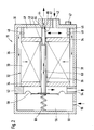
- FIG. 1 shows a simplified, schematic Representation of a fuel supply system Internal combustion engine of a motor vehicle with a Filter device and Figure 2 shows the filter device in enlarged representation in a longitudinal section.
- a fuel supply system is one Internal combustion engine of a motor vehicle shown.
- the Internal combustion engine 10 is preferably a self-igniting Internal combustion engine, a diesel engine.
- the Fuel supply system has a delivery unit 12, by the fuel from a fuel tank 14 is promoted. The funded by the conveyor unit 12 Fuel flows through a filter device 16 which will be explained in more detail below. The fuel will after flowing through the filter device 16 one High pressure pump 18 supplied.
- the high pressure side of the High pressure pump 18 is in the form of a high pressure accumulator 20 of a rail, from which to each cylinder Internal combustion engine 10 has a line 22 to an injector 24 dissipates.
- the filter device 16 has a housing 30 which, for example, approximately is pot-shaped.
- a Filter insert 32 arranged, the at least approximately is designed in the shape of a hollow cylinder Filter cartridge.
- the filter insert 32 has a filter fabric 33 on that at its two axially facing ends is each provided with an annular cover 34.
- the filter insert 32 has a central through opening 35, which is surrounded by the filter fabric 33 approximately coaxially. Between the outer shell of the filter insert 32 and the this surrounding wall 36 of the housing 30 is an annular space 38 formed.
- the housing 30 has one of the cover 34 of the Filter insert 32 opposite floor 40.
- an opening 42 is formed an inlet for the from the conveyor unit 12 from the Fuel tank 14 forms fuel delivered.
- Another is in the bottom 40 of the housing 30 Opening 44 formed to which a return from the Filter device 16 for fuel tank 14 connected.
- the opening 44 is at least approximately coaxial to the through opening 35 of the filter insert 32 arranged.
- the heater 46 is arranged between the bottom 40 of the housing 30 and the latter opposite cover 34 of the filter insert 32 arranged.
- the heater 46 at least has approximately the same external cross section as that Filter insert 32.
- the heating device 46 at least exists partially made of electrically conductive material, in particular Metal.
- the heater 46 is connected to one of the Outside of the housing 30 lying electrical connection 47 connected, the heater 46 when current flows is heated.
- the through the opening 42 in the bottom 40 of the Fuel flowing into housing 30 passes through the bottom 40, the cover 34 of the filter insert 32 and the heater 46 limited space 48.
- the Heater 46 has one distributed over its circumference Plurality of openings 49 through which fuel from the Room 48 can get into the annular space 38.
- the filter insert 32 is based on the heater 46 on the bottom 40 of the Housing 30 from.
- the open side of the housing 30 is with a cover 50 closed, being between the housing 30 and the lid 50 an intermediate plate 52 is arranged.
- the intermediate plate 52 has a smaller internal cross section than that Housing 30 so that the intermediate plate 52 on the support 34 of the filter insert 32 and the filter insert 32 between the heater 46 on the one hand and the Intermediate plate 52 on the other hand in the direction of its longitudinal axis is fixed.
- a seal is provided, to prevent fuel from the annulus 38 can step through.
- In the washer 52 is one Opening 54 formed, to which an outlet to the high pressure pump 18 is connected.
- inflowing fuel passes through openings 49 in of the heater 46 in the annular space 38 and passes through the filter fabric 33 of the filter insert 32 radially inwards into the passage opening 35 and flows from there through the Intermediate plate 52 through its opening 54 to the high pressure pump 18 onwards.
- the space 48 and the annular space 38 are on the Dirt side of the filter device 16 arranged and the Through opening 35 and the interior of the intermediate plate 52 are on the clean side of the filter device 16 arranged.
- That's the opening 44 on the dirt side of the filter device 16 is one Valve device provided by the fuel pressure the clean side of the filter device 16 is controlled.
- the valve device has a space 56 between it Intermediate plate 52 and the cover 50 delimiting movable Wall 58 on.
- the movable wall 58 can, for example be formed by a membrane between the Intermediate plate 52 and the cover 50 is clamped.
- the Membrane 58 is another part of the valve device Rod 60 connected, which is at least approximately coaxial to the Through opening 35 of the filter insert 32 runs and through this passes into room 48 on the Dirt side of the filter device 16.
- the rod 60 can Be graduated in diameter and in front of them Passing through the cover 34 delimiting the space 48 of the filter insert 32 in a smaller diameter Skip section 61.
- Between the rod 60 and the Through opening 35 of the cover 34 is a seal provided by means of a between the rod 60 and the Through opening 35 clamped elastic sealing element 62. Through the sealing element 62, the clean side of the Filter device 16 safely separated from the dirt side.
- the end of the rod 60 protruding into the space 48 serves as Valve member through which the opening 44 in the bottom 40 of the Housing 30 is closable and thus that of the opening 44 to the fuel reservoir 14 returning return is controllable.
- the rod 60 can be a Have bevel 64 acting sealing surface and / or the At its edge, opening 44 can act as a valve seat Have bevel 65 so that a secure seal of the Opening 44 is reached through the end of rod 60.
- the sealing element 62 becomes a guide for the rod 60 reached so that this at least approximately coaxially in the Through opening 35 of the filter insert 32 and at least approximately coaxial with the opening 44 in the bottom 40 of the housing 30 arranged and guided.
- By the Sealing element 62 also exerts a frictional force on the rod 60 generated by the movement of the rod 60 damped becomes. This stimulates pressure vibrations Movement of the rod 60 damped and thus prevented or at least weakened.
- the membrane 58 is on the filter insert 32 facing side of the fuel pressure on the clean side applied to the filter device 16.
- On her other Side is membrane 58 from a reference pressure acted upon.
- the room 56 can, for example, by a Opening 66 in the lid 50 to be connected to the environment, so that the reference pressure acting on the membrane 58 is the Ambient air pressure is.
- room 56 can be accessed via the Opening 66 also with a return to Fuel tank 14 may be connected so that the on the diaphragm 58 acting reference pressure the fuel pressure in Rewind is.
- a spring 68 is also arranged through which the membrane 58 is applied in addition to the reference pressure.
- the feather 68 is between the cover 50 and the membrane 58 clamped.
- the Heating device 46 can be controlled depending on the temperature, so that this falls below a predetermined Temperature is turned on to thicken the Fuel and a resulting addition of the Avoid filter insert 32.
Landscapes
- Engineering & Computer Science (AREA)
- Chemical & Material Sciences (AREA)
- Chemical Kinetics & Catalysis (AREA)
- Combustion & Propulsion (AREA)
- Mechanical Engineering (AREA)
- General Engineering & Computer Science (AREA)
- Fuel-Injection Apparatus (AREA)
- Filtration Of Liquid (AREA)
- Cooling, Air Intake And Gas Exhaust, And Fuel Tank Arrangements In Propulsion Units (AREA)
Abstract
Description
Claims (8)
- Filtervorrichtung für ein Kraftstoffversorgungssystem einer Brennkraftmaschine eines Kraftfahrzeugs mit einem Gehäuse (30,50,52), in dem ein Filtereinsatz (32) angeordnet ist, mit einem schmutzseitig mündenden Zulauf (42) von einem Kraftstoffvorratsbehälter (14), mit einem sauberseitig abführenden Ablauf (54) zur Brennkraftmaschine (10), mit einem schmutzseitig abführenden Rücklauf (44) zum Kraftstoffvorratsbehälter (14), der durch eine Ventileinrichtung gesteuert wird, die eine vom Kraftstoffdruck auf der Sauberseite der Filtervorrichtung (16) beaufschlagte bewegliche Wand (58) aufweist und durch die der Rücklauf (44) geschlossen gehalten wird, bis der Kraftstoffdruck auf der Sauberseite einen vorgegebenen Wert überschreitet, wonach der Rücklauf (44) durch die Ventileinrichtung freigegeben wird, dadurch gekennzeichnet, daß die Ventileinrichtung eine durch die bewegliche Wand (58) verschiebbare Stange (60) aufweist, die durch den Filtereinsatz (32) von der Sauberseite zur Schmutzseite hindurchtritt und durch deren auf der Schmutzseite angeordneten Endbereich der Rücklauf (44) gesteuert wird.
- Filtervorrichtung nach Anspruch 1, dadurch gekennzeichnet, daß der Endbereich der Stange (60) als Dichtfläche (64) ausgebildet ist und mit einem eine Öffnung (44) des Rücklaufs umgebenden Ventilsitz (65) zusammenwirkt.
- Filtervorrichtung nach Anspruch 1 öder 2, dadurch gekennzeichnet, daß der Filtereinsatz (32) zumindest annähernd hohlzylinderförmig ausgebildet ist mit einer zentralen Durchgangsöffnung (35), durch die die Stange (60) hindurchtritt.
- Filtervorrichtung nach einem der Ansprüche 1 bis 3, dadurch gekennzeichnet, daß die bewegliche Wand (58) auf ihrer anderen Seite, die der vom Kraftstoffdruck auf der Sauberseite beaufschlagten Seite gegenüberliegt, von einem Referenzdruck beaufschlagt ist.
- Filtervorrichtung nach einem der Ansprüche 1 bis 4, dadurch gekennzeichnet, daß die bewegliche Wand (58) auf ihrer anderen Seite, die der vom Kraftstoffdruck auf der Sauberseite beaufschlagten Seite gegenüberliegt, von einem federnden Element (68) beaufschlagt ist.
- Filtervorrichtung nach einem der vorstehenden Ansprüche, dadurch gekennzeichnet, daß zwischen dem Filtereinsatz (32) und der Stange (60) ein elastisches Dichtelement (62) eingespannt ist, über das die Stange (60) verschiebbar geführt ist.
- Filtervorrichtung nach Anspruch 6, dadurch gekennzeichnet, daß durch das Dichtelement (62) eine Reibkraft auf die Stange (60) erzeugt wird, durch die eine Verschiebebewegung der Stange (60) gedämpft wird.
- Filtervorrichtung nach einem der vorstehenden Ansprüche, dadurch gekennzeichnet, daß diese eine auf der Schmutzseite angeordnete Heizvorrichtung (46) aufweist.
Applications Claiming Priority (2)
| Application Number | Priority Date | Filing Date | Title |
|---|---|---|---|
| DE19963388 | 1999-12-28 | ||
| DE19963388A DE19963388A1 (de) | 1999-12-28 | 1999-12-28 | Filtervorrichtung für ein Kraftstoffversorgungssystem einer Brennkraftmaschine eines Fahrzeugs |
Publications (3)
| Publication Number | Publication Date |
|---|---|
| EP1113164A2 true EP1113164A2 (de) | 2001-07-04 |
| EP1113164A3 EP1113164A3 (de) | 2002-05-29 |
| EP1113164B1 EP1113164B1 (de) | 2006-03-22 |
Family
ID=7934756
Family Applications (1)
| Application Number | Title | Priority Date | Filing Date |
|---|---|---|---|
| EP00125721A Expired - Lifetime EP1113164B1 (de) | 1999-12-28 | 2000-11-24 | Filtervorrichtung für ein Kraftstoffversorgungssystem einer Brennkraftmaschine eines Kraftfahrzeugs |
Country Status (4)
| Country | Link |
|---|---|
| US (1) | US6391194B2 (de) |
| EP (1) | EP1113164B1 (de) |
| JP (1) | JP2001221117A (de) |
| DE (2) | DE19963388A1 (de) |
Cited By (2)
| Publication number | Priority date | Publication date | Assignee | Title |
|---|---|---|---|---|
| ITVI20120220A1 (it) * | 2012-09-10 | 2014-03-11 | T A Fin S R L | Apparecchiatura per l¿alimentazione di un motore a combustione interna con gas combustibile. |
| WO2018219759A1 (de) * | 2017-05-30 | 2018-12-06 | Robert Bosch Gmbh | Filtergehäuse sowie zwischenboden |
Families Citing this family (5)
| Publication number | Priority date | Publication date | Assignee | Title |
|---|---|---|---|---|
| US7708792B2 (en) * | 2006-01-12 | 2010-05-04 | Delphi Technologies, Inc. | Air inlet assembly |
| CA2919693C (en) | 2013-08-02 | 2020-03-24 | Alternative Fuel Containers, Llc | Vehicle fuel gas pre-filter unit |
| KR101478965B1 (ko) | 2014-04-30 | 2015-01-06 | 주식회사 엠씨엠 | 필터 조립체 |
| BR102015009994B1 (pt) * | 2014-05-05 | 2022-02-08 | Mann+Hummel Gmbh | Dispositivo de filtração e elemento de filtração para um dispositivo de filtração |
| DE102017006063A1 (de) * | 2017-06-27 | 2018-12-27 | Hydac Accessories Gmbh | Prüfvorrichtung zum Ermitteln der Partikelbelastung von unter einem hohen Druck stehendem Wasserstoff |
Citations (1)
| Publication number | Priority date | Publication date | Assignee | Title |
|---|---|---|---|---|
| US5078167A (en) | 1990-12-18 | 1992-01-07 | Parr Manufacturing, Inc. | Fuel filter and pressure regulator system apparatus |
Family Cites Families (14)
| Publication number | Priority date | Publication date | Assignee | Title |
|---|---|---|---|---|
| US1368475A (en) * | 1921-02-15 | blakely | ||
| US2423329A (en) * | 1942-01-24 | 1947-07-01 | Clair Camille Clare Sprankl Le | Oil filtration |
| JPS59190462A (ja) * | 1983-04-12 | 1984-10-29 | Nippon Denso Co Ltd | 燃料加熱型燃料フイルタ装置 |
| US4556077A (en) * | 1983-12-20 | 1985-12-03 | Allied Corporation | Switching valve for a fuel supply system |
| JPS62121857A (ja) * | 1985-11-22 | 1987-06-03 | Daihatsu Motor Co Ltd | 燃料加熱装置 |
| JPH0537016Y2 (de) * | 1987-03-24 | 1993-09-20 | ||
| JP2751142B2 (ja) * | 1990-11-14 | 1998-05-18 | ダイハツ工業株式会社 | ディーゼル機関における燃料供給装置 |
| US5195494A (en) * | 1992-02-27 | 1993-03-23 | Walbro Corporation | Fuel delivery system with outlet pressure regulation |
| DE4430471A1 (de) * | 1994-08-27 | 1996-02-29 | Bosch Gmbh Robert | Flüssigkeitsfilter mit eingebautem Druckregler |
| DE19523626A1 (de) * | 1995-06-29 | 1997-01-02 | Daimler Benz Ag | Druckregelventil für in Verbrennungsmotoren einzuspritzenden Kraftstoff und Integration dieses Druckregelventils in ein Kraftstoffilter |
| JPH09105366A (ja) * | 1995-08-08 | 1997-04-22 | Tenetsukusu:Kk | 燃料フイルタ |
| DE19536084A1 (de) * | 1995-09-28 | 1997-04-03 | Bosch Gmbh Robert | Flüssigkeitsfilter mit eingebautem Druckregler |
| DE19736846A1 (de) * | 1997-08-23 | 1999-03-04 | Mannesmann Vdo Ag | Druckregelanordnung |
| DE19753611A1 (de) * | 1997-12-03 | 1999-06-10 | Bosch Gmbh Robert | Flüssigkeitsfilter mit eingebautem Druckregler für Kraftstoff |
-
1999
- 1999-12-28 DE DE19963388A patent/DE19963388A1/de not_active Withdrawn
-
2000
- 2000-11-24 EP EP00125721A patent/EP1113164B1/de not_active Expired - Lifetime
- 2000-11-24 DE DE50012436T patent/DE50012436D1/de not_active Expired - Lifetime
- 2000-12-25 JP JP2000393553A patent/JP2001221117A/ja active Pending
- 2000-12-26 US US09/748,406 patent/US6391194B2/en not_active Expired - Fee Related
Patent Citations (1)
| Publication number | Priority date | Publication date | Assignee | Title |
|---|---|---|---|---|
| US5078167A (en) | 1990-12-18 | 1992-01-07 | Parr Manufacturing, Inc. | Fuel filter and pressure regulator system apparatus |
Cited By (2)
| Publication number | Priority date | Publication date | Assignee | Title |
|---|---|---|---|---|
| ITVI20120220A1 (it) * | 2012-09-10 | 2014-03-11 | T A Fin S R L | Apparecchiatura per l¿alimentazione di un motore a combustione interna con gas combustibile. |
| WO2018219759A1 (de) * | 2017-05-30 | 2018-12-06 | Robert Bosch Gmbh | Filtergehäuse sowie zwischenboden |
Also Published As
| Publication number | Publication date |
|---|---|
| DE50012436D1 (de) | 2006-05-11 |
| EP1113164A3 (de) | 2002-05-29 |
| JP2001221117A (ja) | 2001-08-17 |
| US6391194B2 (en) | 2002-05-21 |
| EP1113164B1 (de) | 2006-03-22 |
| DE19963388A1 (de) | 2001-07-05 |
| US20010005985A1 (en) | 2001-07-05 |
Similar Documents
| Publication | Publication Date | Title |
|---|---|---|
| EP0678668B1 (de) | Kraftstoffeinspritzeinrichtung für Brennkraftmaschinen | |
| DE69406783T2 (de) | Zusammenbau einer filterpatrone für ein oberseitig gespeistes kraftstoffeinspritzventil | |
| DE19649554B4 (de) | Membrandruckregelventilanordnung | |
| DE4431996A1 (de) | Vorrichtung für die Kraftstoffzufuhr | |
| DE102009049868A1 (de) | Filtereinrichtung | |
| DE60020731T2 (de) | Kraftstoffrückführventil mit entlüftung | |
| DE4426667A1 (de) | Vorrichtung zum Fördern von Kraftstoff aus einem Vorratsbehälter zur Brennkraftmaschine eines Kraftfahrzeuges | |
| DE19846601A1 (de) | Sammel- und Druckentlastungsmodul für eine Kraftstoffzuführanlage | |
| DE112007000428T5 (de) | Kraftstoffzufuhrvorrichtung | |
| EP0657644A2 (de) | Kraftstoffeinspritzeinrichtung für Brennkraftmaschinen | |
| DE2407302A1 (de) | Kraftstoffbehaelter mit einer vorrichtung zum begrenzen der menge ausstroemender kraftstoffdaempfe | |
| DE9112163U1 (de) | Drossel mit Druckbegrenzungsventil zur Dämpfung von Druckschwingungen | |
| EP1907689B1 (de) | Kraftstoffinjektor | |
| EP1664522B1 (de) | Filterbaueinheit und ventil für ein kraftstoffversorgungssystem | |
| DE2642177C2 (de) | Elektrisch gesteuertes Kraftstoffeinspritzsystem für Dieselbrennkraftmaschinen | |
| EP0887544A1 (de) | Kraftstoffeinspritzsystem für Brennkraftmaschinen | |
| EP1113164A2 (de) | Filtervorrichtung für ein Kraftstoffversorgungssystem einer Brennkraftmaschine eines Kraftfahrzeugs | |
| DE2810211A1 (de) | Heizwassersteuerventil fuer eine kraftfahrzeug-heizungsanlage | |
| DE102006025064A1 (de) | Thermostatventil | |
| EP3037150B1 (de) | Filtereinrichtung | |
| DE2740879A1 (de) | Einspritzventil fuer hubkolbenbrennkraftmaschinen | |
| EP1005610B1 (de) | Druckregelanordnung | |
| EP0922850B1 (de) | Kraftstoffversorgungssystem | |
| DE10223025B4 (de) | Druckreduzierventil | |
| DE3606916A1 (de) | Wartungsgeraet fuer ein pneumatisches druckmittel |
Legal Events
| Date | Code | Title | Description |
|---|---|---|---|
| PUAI | Public reference made under article 153(3) epc to a published international application that has entered the european phase |
Free format text: ORIGINAL CODE: 0009012 |
|
| AK | Designated contracting states |
Kind code of ref document: A2 Designated state(s): AT BE CH CY DE DK ES FI FR GB GR IE IT LI LU MC NL PT SE TR |
|
| AX | Request for extension of the european patent |
Free format text: AL;LT;LV;MK;RO;SI |
|
| PUAL | Search report despatched |
Free format text: ORIGINAL CODE: 0009013 |
|
| AK | Designated contracting states |
Kind code of ref document: A3 Designated state(s): AT BE CH CY DE DK ES FI FR GB GR IE IT LI LU MC NL PT SE TR |
|
| AX | Request for extension of the european patent |
Free format text: AL;LT;LV;MK;RO;SI |
|
| 17P | Request for examination filed |
Effective date: 20021129 |
|
| AKX | Designation fees paid |
Designated state(s): DE FR GB IT |
|
| GRAP | Despatch of communication of intention to grant a patent |
Free format text: ORIGINAL CODE: EPIDOSNIGR1 |
|
| GRAS | Grant fee paid |
Free format text: ORIGINAL CODE: EPIDOSNIGR3 |
|
| GRAA | (expected) grant |
Free format text: ORIGINAL CODE: 0009210 |
|
| AK | Designated contracting states |
Kind code of ref document: B1 Designated state(s): DE FR GB IT |
|
| PG25 | Lapsed in a contracting state [announced via postgrant information from national office to epo] |
Ref country code: IT Free format text: LAPSE BECAUSE OF FAILURE TO SUBMIT A TRANSLATION OF THE DESCRIPTION OR TO PAY THE FEE WITHIN THE PRESCRIBED TIME-LIMIT;WARNING: LAPSES OF ITALIAN PATENTS WITH EFFECTIVE DATE BEFORE 2007 MAY HAVE OCCURRED AT ANY TIME BEFORE 2007. THE CORRECT EFFECTIVE DATE MAY BE DIFFERENT FROM THE ONE RECORDED. Effective date: 20060322 |
|
| REG | Reference to a national code |
Ref country code: GB Ref legal event code: FG4D Free format text: NOT ENGLISH |
|
| REF | Corresponds to: |
Ref document number: 50012436 Country of ref document: DE Date of ref document: 20060511 Kind code of ref document: P |
|
| GBT | Gb: translation of ep patent filed (gb section 77(6)(a)/1977) |
Effective date: 20060706 |
|
| ET | Fr: translation filed | ||
| PLBE | No opposition filed within time limit |
Free format text: ORIGINAL CODE: 0009261 |
|
| STAA | Information on the status of an ep patent application or granted ep patent |
Free format text: STATUS: NO OPPOSITION FILED WITHIN TIME LIMIT |
|
| 26N | No opposition filed |
Effective date: 20061227 |
|
| PGFP | Annual fee paid to national office [announced via postgrant information from national office to epo] |
Ref country code: GB Payment date: 20091123 Year of fee payment: 10 |
|
| PGFP | Annual fee paid to national office [announced via postgrant information from national office to epo] |
Ref country code: IT Payment date: 20101126 Year of fee payment: 11 |
|
| GBPC | Gb: european patent ceased through non-payment of renewal fee |
Effective date: 20101124 |
|
| PG25 | Lapsed in a contracting state [announced via postgrant information from national office to epo] |
Ref country code: GB Free format text: LAPSE BECAUSE OF NON-PAYMENT OF DUE FEES Effective date: 20101124 |
|
| PGFP | Annual fee paid to national office [announced via postgrant information from national office to epo] |
Ref country code: FR Payment date: 20111125 Year of fee payment: 12 |
|
| PGFP | Annual fee paid to national office [announced via postgrant information from national office to epo] |
Ref country code: DE Payment date: 20120124 Year of fee payment: 12 |
|
| REG | Reference to a national code |
Ref country code: FR Ref legal event code: ST Effective date: 20130731 |
|
| PG25 | Lapsed in a contracting state [announced via postgrant information from national office to epo] |
Ref country code: IT Free format text: LAPSE BECAUSE OF NON-PAYMENT OF DUE FEES Effective date: 20121124 |
|
| REG | Reference to a national code |
Ref country code: DE Ref legal event code: R119 Ref document number: 50012436 Country of ref document: DE Effective date: 20130601 |
|
| PG25 | Lapsed in a contracting state [announced via postgrant information from national office to epo] |
Ref country code: DE Free format text: LAPSE BECAUSE OF NON-PAYMENT OF DUE FEES Effective date: 20130601 |
|
| PG25 | Lapsed in a contracting state [announced via postgrant information from national office to epo] |
Ref country code: FR Free format text: LAPSE BECAUSE OF NON-PAYMENT OF DUE FEES Effective date: 20121130 |