EP1114608B1 - Eye observation apparatus having a plurality of individually controlled LEDs for colour corrected illumination - Google Patents
Eye observation apparatus having a plurality of individually controlled LEDs for colour corrected illumination Download PDFInfo
- Publication number
- EP1114608B1 EP1114608B1 EP00128727A EP00128727A EP1114608B1 EP 1114608 B1 EP1114608 B1 EP 1114608B1 EP 00128727 A EP00128727 A EP 00128727A EP 00128727 A EP00128727 A EP 00128727A EP 1114608 B1 EP1114608 B1 EP 1114608B1
- Authority
- EP
- European Patent Office
- Prior art keywords
- light
- leds
- observation
- ophthalmic apparatus
- illumination
- Prior art date
- Legal status (The legal status is an assumption and is not a legal conclusion. Google has not performed a legal analysis and makes no representation as to the accuracy of the status listed.)
- Expired - Lifetime
Links
- 238000005286 illumination Methods 0.000 title claims description 73
- 230000003287 optical effect Effects 0.000 claims description 63
- 238000011282 treatment Methods 0.000 claims description 27
- 230000001681 protective effect Effects 0.000 claims description 16
- 238000001514 detection method Methods 0.000 claims description 9
- 238000003780 insertion Methods 0.000 claims description 7
- 230000037431 insertion Effects 0.000 claims description 7
- 230000001678 irradiating effect Effects 0.000 claims description 2
- 238000013532 laser treatment Methods 0.000 description 9
- 239000000835 fiber Substances 0.000 description 4
- 230000007246 mechanism Effects 0.000 description 4
- 230000008859 change Effects 0.000 description 3
- 238000010586 diagram Methods 0.000 description 3
- 230000005540 biological transmission Effects 0.000 description 2
- 239000003086 colorant Substances 0.000 description 2
- 230000003247 decreasing effect Effects 0.000 description 2
- 230000000694 effects Effects 0.000 description 2
- GNBHRKFJIUUOQI-UHFFFAOYSA-N fluorescein Chemical compound O1C(=O)C2=CC=CC=C2C21C1=CC=C(O)C=C1OC1=CC(O)=CC=C21 GNBHRKFJIUUOQI-UHFFFAOYSA-N 0.000 description 2
- 230000004907 flux Effects 0.000 description 2
- 229910052736 halogen Inorganic materials 0.000 description 2
- 150000002367 halogens Chemical class 0.000 description 2
- 230000000649 photocoagulation Effects 0.000 description 2
- 230000004044 response Effects 0.000 description 2
- WFKWXMTUELFFGS-UHFFFAOYSA-N tungsten Chemical compound [W] WFKWXMTUELFFGS-UHFFFAOYSA-N 0.000 description 2
- 229910052721 tungsten Inorganic materials 0.000 description 2
- 239000010937 tungsten Substances 0.000 description 2
- 230000005856 abnormality Effects 0.000 description 1
- 210000004204 blood vessel Anatomy 0.000 description 1
- 210000000795 conjunctiva Anatomy 0.000 description 1
- 230000001419 dependent effect Effects 0.000 description 1
- 230000000881 depressing effect Effects 0.000 description 1
- 230000000994 depressogenic effect Effects 0.000 description 1
- 238000002059 diagnostic imaging Methods 0.000 description 1
- 230000020169 heat generation Effects 0.000 description 1
- 238000010438 heat treatment Methods 0.000 description 1
- 238000009434 installation Methods 0.000 description 1
- 239000000463 material Substances 0.000 description 1
- 239000000203 mixture Substances 0.000 description 1
- 239000004065 semiconductor Substances 0.000 description 1
- 238000001228 spectrum Methods 0.000 description 1
- 230000000007 visual effect Effects 0.000 description 1
Images
Classifications
-
- A—HUMAN NECESSITIES
- A61—MEDICAL OR VETERINARY SCIENCE; HYGIENE
- A61B—DIAGNOSIS; SURGERY; IDENTIFICATION
- A61B3/00—Apparatus for testing the eyes; Instruments for examining the eyes
- A61B3/0008—Apparatus for testing the eyes; Instruments for examining the eyes provided with illuminating means
-
- A—HUMAN NECESSITIES
- A61—MEDICAL OR VETERINARY SCIENCE; HYGIENE
- A61F—FILTERS IMPLANTABLE INTO BLOOD VESSELS; PROSTHESES; DEVICES PROVIDING PATENCY TO, OR PREVENTING COLLAPSING OF, TUBULAR STRUCTURES OF THE BODY, e.g. STENTS; ORTHOPAEDIC, NURSING OR CONTRACEPTIVE DEVICES; FOMENTATION; TREATMENT OR PROTECTION OF EYES OR EARS; BANDAGES, DRESSINGS OR ABSORBENT PADS; FIRST-AID KITS
- A61F9/00—Methods or devices for treatment of the eyes; Devices for putting in contact-lenses; Devices to correct squinting; Apparatus to guide the blind; Protective devices for the eyes, carried on the body or in the hand
- A61F9/08—Devices or methods enabling eye-patients to replace direct visual perception by another kind of perception
-
- A—HUMAN NECESSITIES
- A61—MEDICAL OR VETERINARY SCIENCE; HYGIENE
- A61B—DIAGNOSIS; SURGERY; IDENTIFICATION
- A61B3/00—Apparatus for testing the eyes; Instruments for examining the eyes
- A61B3/10—Objective types, i.e. instruments for examining the eyes independent of the patients' perceptions or reactions
- A61B3/12—Objective types, i.e. instruments for examining the eyes independent of the patients' perceptions or reactions for looking at the eye fundus, e.g. ophthalmoscopes
-
- A—HUMAN NECESSITIES
- A61—MEDICAL OR VETERINARY SCIENCE; HYGIENE
- A61B—DIAGNOSIS; SURGERY; IDENTIFICATION
- A61B3/00—Apparatus for testing the eyes; Instruments for examining the eyes
- A61B3/10—Objective types, i.e. instruments for examining the eyes independent of the patients' perceptions or reactions
- A61B3/13—Ophthalmic microscopes
Definitions
- the filter 57 is arranged to be insertable into or removable from the observation optical path by means of a movement mechanism constructed of a motor or the like (not shown). The insertion and removal of the filter 57 with respect to the observation optical path is effected based on the presence or absence of the trigger signal from the foot switch 5. The condition of the filter 57, or the presence or absence of the filter 57 in the observation optical path, is detected by means of a sensor 57a.
- the illumination light beams from the LEDs 41a, 41b, and 41c are composed by the dichroic mirrors 80 and 81, whereby substantially white illumination light is produced as described above, which illuminates the patient's 'eye E through the illumination optical system 40.
- the operator can observe through the observation optical system 50 the fundus of the patient's eye E illuminated by the white illumination light.
- the above embodiment has described an example of using three types of LEDs for emitting beams of illumination light of wavelengths in regions for R, G, and B.
- the types of LEDs for emitting beams of illumination light of wavelengths in different regions from the above three regions may be further increased so that the substantially white illumination light is easily obtained.
- the number of LEDs may be increased for each color.
- the LED 41b for emitting green illumination light is lit without illumination by red illumination light, thereby facilitating the observation.
- an LED for emitting light of wavelengths required for the fluorescence observation or the like may be provided in advance as an LED for an illumination light source.
Landscapes
- Health & Medical Sciences (AREA)
- Life Sciences & Earth Sciences (AREA)
- General Health & Medical Sciences (AREA)
- Veterinary Medicine (AREA)
- Heart & Thoracic Surgery (AREA)
- Biomedical Technology (AREA)
- Engineering & Computer Science (AREA)
- Animal Behavior & Ethology (AREA)
- Ophthalmology & Optometry (AREA)
- Public Health (AREA)
- Physics & Mathematics (AREA)
- Vascular Medicine (AREA)
- Biophysics (AREA)
- Medical Informatics (AREA)
- Molecular Biology (AREA)
- Surgery (AREA)
- Eye Examination Apparatus (AREA)
- Laser Surgery Devices (AREA)
- Radiation-Therapy Devices (AREA)
Description
- The present invention relates to an ophthalmic apparatus for performing observation or treatment by illuminating an eye of a patient.
- As an ophthalmic apparatus for observing a patient's eye, there is known a slit lamp for projecting slit-shaped illumination light on the patient's eye, thereby allowing observation through an observation optical system, or a laser treatment apparatus constructed by a combination of the slit lamp and a laser irradiation device.
- These ophthalmic apparatus each cause an illumination light source provided inside of the apparatus to project illumination light on the patient's eye to thereby performing observation and treatment. A tungsten lamp, a halogen lamp or the like is generally used for the illumination light source.
- However, an illumination light source using a lamp is short in service life. Thus, such illumination light source requires frequent replacement, which is cumbersome and imposes burden on operators or the like. In addition, the lamp has a large heat rate during illumination, and may have a thermal effect on its periphery. It is therefore required to pay attention to a material or an installation position, etc. of the periphery of the illumination light source during design.
- The slip lamp is provided with a mechanism to insert/remove a wavelength selection filter for enabling fluorescent observation or the like into/from an illumination optical path. This may increase complexity in configuration of the apparatus.
- The US-A-5 997 141 discloses an ophthalmic apparatus including an illumination system for illuminating an eye of a patient, including a plurality of LEDs and a composing optical system for composing optical parts of beams of light emitted from the LEDs; an observation system for observing the patient's eye; and light quantity control means for controlling an illumination light quantity of each of the LEDs.
- Furthermore, WO-A-96/05693 describes controlled individual LED illumination for medical imaging, and US-A-3 760 174 describes controlled LEDs to provide a given illumination spectrum.
- In many cases, a laser treatment apparatus for performing photocoagulation or the like is provided with a protective filter disposed in an observation optical path in order to protect an operator's eye from a laser beam for treatment reflected from the patient's eye or the like. However, in the case of observation through a protective filter for cutting a visible treatment laser beam, an observation image looks more colorful than that in the case where no protective filter is provided, has strangeness, and makes it difficult to ensure observation.
- The present invention has been made in view of the above mentioned technical problems. It is an object of the present invention to provide an ophthalmic apparatus provided with an illumination light source which is easy-to-handle and arranged in simplified configuration.
- Another object of the present invention is providing an ophthalmic apparatus capable of facilitating observation even in the presence of a protective filter during laser treatment.
- In order to solve the foregoing problems, the present invention provides an ophthalmic apparatus according to
claim 1. Preferred embodiments are set forth independent claims 2 to 9. - The accompanying drawings, which are incorporated in and constitute a part of this specification illustrate an embodiment of the invention and, together with the description, serve to explain the objects, advantages and principles of the invention.
- In the drawings,
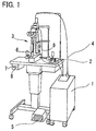
- Fig. 1 is an external view showing a laser treatment apparatus in an embodiment according to the present invention;
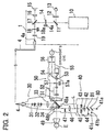
- Fig. 2 is a schematic view showing an optical system of the apparatus;
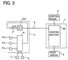
- Fig. 3 is a block diagram schematically showing a control system of the apparatus;
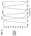
- Fig. 4 is a view showing wavelength characteristics of each LED;
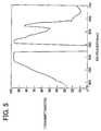
- Fig. 5 is a view showing wavelength transmission characteristics of a protective filter; and
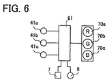
- Fig. 6 is a block diagram schematically showing a mechanism for selectively lighting LEDs.
-
- A detailed description of a preferred embodiment of an ophthalmic apparatus embodying the present invention will now be given referring to the accompanying drawings. The present embodiment exemplifies a laser treatment apparatus as the ophthalmic apparatus according to the present invention. Fig. 1 is an external view showing a laser treatment apparatus for performing photocoagulation treatment by irradiating a laser light beam for treatment (hereinafter, merely referred to as a treatment beam) to the periphery an affected part of a patient's eye. Fig. 2 is a schematic view showing an optical system of the apparatus.
-
Reference numeral 1 denotes a main body of the laser treatment apparatus. Reference -numeral 2 is a control board for setting and inputting irradiation output conditions of the treatment beam.Reference numeral 3 denotes a slit lamp delivery comprising a laser irradiationoptical system 30, an illuminationoptical system 40, and an observationoptical system 50.Reference numeral 4 is a fiber cable for delivering the treatment beam or an aiming laser light beam (hereinafter, merely referred to as an aiming beam) from themain body 1 to theslit lamp delivery 3.Reference numeral 5 is a foot switch for generating a trigger signal to start laser irradiation.Reference numeral 6 is a joystick for moving theslit lamp delivery 3. - Reference numeral 7 denotes a switch for
lighting LEDs 41a-41c that constitute an illumination light source incorporated in theslit lamp delivery 3.Reference numeral 8 denotes a light adjusting knob for adjusting an illumination light quantity.Reference numeral 9 is a cable connecting between theslit lamp delivery 3 and a control section 60 (see Fig. 3) on the side of themain body 1. Thecable 9 is used for transmitting and receiving a command signal to insert/remove aprotective filter 57 with respect to an optical path of the observation optical system 50 (hereinafter, referred to as an observation optical path) or a detection signal indicating the insertion or removal of the filter 57 (i.e. the presence or absence of thefilter 57 in the observation optical path). Thecable 9 is also used to transmit whether thefoot switch 5 is active or inactive to theslit lamp delivery 3. -
Reference numeral 10 denotes a laser source for emitting a treatment beam. In the present embodiment, as thelaser source 10, an Nd:YAG laser capable of oscillating a fundamental wave of 1064nm is used to generate a green light of 532nm (linearly polarized light), which is double the fundamental wave. Reference numeral 11 is a beam splitter having the property of transmitting most part of the treatment beam emitted from thelaser source 10 while reflecting a part of the beam. The part of the treatment beam reflected by the beam splitter 11 enters anoutput sensor 13 through adiffusing plate 12 for detecting the output value of the treatment beam. -
Reference numeral 14 is a safety shutter. When thefoot switch 5 is depressed, issuing a command for laser irradiation (i.e. generating a trigger signal), thesafety shutter 14 is removed from the optical path, thus enabling the passing of the treatment beam. In case where an abnormality occurs, thesafety shutter 14 is inserted into the optical path to thereby intercept the laser beam. The opening and closing of thisshutter 14 is detected by means of ashutter sensor 14a. -
Reference numeral 15 denotes a laser light source for emitting an aiming beam. In the present embodiment, there is used a semiconductor laser source capable of emitting a red aiming beam of 630 nm. The aiming beam emitted from thelight source 15 passes through acollimator lens 16 and is made coaxial to the treatment beam by means of adichroic mirror 17. -
Reference numeral 18 is a second safety shutter. The opening and closing of thisshutter 18 is detected by ashutter sensor 18a.Reference numeral 19 denotes a focusing lens for focusing the laser beams (the treatment beam and the aiming beam) to anincident end face 4a to enter thefiber 4. The laser beams are delivered through thefiber 4 to the irradiationoptical system 30 of theslit lamp delivery 3. - The irradiation
optical system 30 comprises acollimator lens 31, a variablemagnification lens group 32, anobjective lens 33, and adriving mirror 34. An operator can operate a manipulator (not shown), whereby to change the reflection angle of the drivingmirror 34 to fine adjust a laser irradiation position. -
Reference numeral 40 denotes an illumination optical system.Reference numerals LEDs 41a-41c emit beams of illumination light in wavelength regions for red (R), green (G), and blue (B), respectively, that are the primary colors of light. - The wavelength characteristics of each of the
LEDs LED 41a emits illumination light of the blue wavelength region of which a peak light emission wavelength is close to 460 nm, and the blue illumination light is allowed to pass throughdichroic mirrors LED 41b emits illumination light of a green wavelength region of which a peak light emission wavelength is close to 520 nm. The green illumination light is reflected by thedichroic mirror 80 to be composed with the blue illumination light. Then, the resultant light is allowed to pass through thedichroic mirror 81. TheLED 41c emits illumination light of a red wavelength region of which a peak light emission wavelength is close to 630 nm. The red illumination light is reflected by thedichroic mirror 81 to be composed with the beams of blue and green illumination light. - In the present embodiment, although the
dichroic mirrors - The beams of visible illumination light emitted from the
LEDs 41a-41c and made coaxial (composed with each other) on the optical axis L are allowed to pass through acondenser lens 42. A height and a width of the resultant light are determined by a variablecircular aperture plate 43 and avariable slit plate 44 respectively to be formed into a slit-shaped luminous flux. Then, the slit-shaped illumination light is allowed to pass through aprojection lens 46 and then reflected by dividingmirrors contact lens 49.Reference numeral 47 is a correction lens, andreference numeral 45 is a wavelength selection filter to be inserted into or removed from the optical path of the illumination optical system 40 (hereinafter, referred to as illumination optical path). - An observation
optical system 50 comprises: anobjective lens 51 shared between the left and right observation optical paths; avariable magnification lens 52; animage forming lens 53; anerect prism 54; afield diaphragm 55;eyepiece lenses 56; and theprotective filter 57; the elements 53-57 being disposed in the left and right observation optical paths, respectively. Fig. 5 is a view showing wavelength transmission characteristics of thefilter 57. Thefilter 57 used in the present embodiment has the property of cutting 99% or more of light of a narrow bandwidth wavelength region (520nm-540nm), the center of which is 532 nm of the treatment beam, while allowing most of light of the visible wavelength region. - The
filter 57 is arranged to be insertable into or removable from the observation optical path by means of a movement mechanism constructed of a motor or the like (not shown). The insertion and removal of thefilter 57 with respect to the observation optical path is effected based on the presence or absence of the trigger signal from thefoot switch 5. The condition of thefilter 57, or the presence or absence of thefilter 57 in the observation optical path, is detected by means of asensor 57a. - Operation of the apparatus constructed as above will be described with reference to a block diagram schematically showing a control system shown in Fig. 3.
- An operator turns on the
LEDs 41a-41c by means of the switch 7. At this time, the light quantity of each of the illumination light beams emitted from theLEDs 41a-41c is controlled in advance by a lightquantity control section 61 so that white illumination light is produced after three luminous fluxes (red, green, and blue) have been composed. To be more specific, the light quantities of theLEDs LED 41a:LED 41b:LED 41c (B:G:R) = 0.5:0.6:1.0. - As a result, the illumination light beams emitted from the
LEDs 41a-41c are changed into a substantially white illumination light after they are composed; the white illumination light illuminates the patient's eye E; and the operator can obtain an observation image (observation visual field) in close to a natural color. It is to be noted that the light quantity ratio is not limited to the above, another ratio may be adopted if only the color of the illumination light produced by composition is within a region of white light. - Even when the light quantity of illumination light projected to the patient's eye E is changed by using the
light adjusting knob 8, the light quantity is increased or decreased by the lightquantity control section 61 without changing the ratio of the light emission quantities of theLEDs 41a-41c. This makes it possible to maintain the illumination light after composed in a substantially white color. - Since the LED is used as the illumination light source in the present embodiment, heating quantity can be reduced, thus eliminating the need to consider a thermal effect caused by the illumination light from the LED. Such each LED has its long service life, and may not be frequently replaced.
- The illumination light beams from the
LEDs optical system 40. The operator can observe through the observationoptical system 50 the fundus of the patient's eye E illuminated by the white illumination light. - Next, the aiming
laser source 15 is lit by a switch (not shown) on thecontrol board 2. Upon setting of the emission of the aiming beam, thecontrol section 60 causes theshutter 18 to be removed from the optical path. - The operator operates the
joystick 6 and a manipulator (not shown) while observing the aiming beam irradiated to the eye fundus, and performs alignment with respect to an affected part of the eye fundus. The operator sets irradiation conditions such as the irradiation power or irradiation time of the treatment beam by using various switches on thecontrol board 2. When the laser irradiation is ready, a READY status is established such that the irradiation of the treatment beam is enabled. Then, the operator operates the manipulator (not shown) to make fine adjustment for alignment with the affected part. After completion of the alignment, the operator depresses thefoot switch 5 to start the laser irradiation. Upon receipt of the trigger signal from thefoot switch 5, thecontrol section 60 generates a command signal to insert thefilter 57 into the observation optical path. Thesensor 57a detects that thefilter 57 is inserted into the observation optical path and transmits the detection signal to the lightquantity control section 61. - Upon receipt of the detection signal from the
sensor 57a, the lightquantity control section 61 changes the ratio of the light quantities of theLEDs 41a-41c in synchronization with the insertion of thefilter 57 into the observation optical path. A change quantity of this light quantity ratio is preset so that the light densities of R, G, and B that pass through thefilter 57 are close to those obtained in the absence of thefilter 57 in the observation optical path. - The above change of the light quantity ratio by the light
quantity control section 61 is effected for the following reason. - That is, when the reflection light from the patient's eye E passes through the
filter 57, light of wavelengths in a range of 520nm to 540nm is cut by thefilter 57 in order to cut the treatment beam. In association with this, the density of the green light is reduced. In this case, the ratio of the light quantities of the light beams passed through thefilter 57 becomes the following relation; B:G:R = 0.8:0.3:1.0. Consequently, the entire observation image obtained during observation through thefilter 57 is more colorful (purplish) than that obtained in the absence of thefilter 57. - To compensate for the density of the green light cut by the
filter 57, the density of light of a green wavelength region which is allowed to pass through thefilter 57 is relatively increased. - The ratio of respective light quantities of the
LEDs 41a-41c is changed, for example, by increasing the light quantity ofLED 41b, while decreasing those of theLEDs filter 57 is adjusted to the relation; B:G:R = 0.5:0.6:1.0. In this case, the ratio of respective actual light quantities of the LEDs shows the following relation;LED 41a :LED 41b :LED 41c (B:G:R) = 0.3:1.0:0.9. In this manner, the colored degree of an observation image is lowered, and an observation image produced in the presence of thefilter 57 in the observation optical path can be given the tone close to the observation image produced in the absence of thefilter 57 therein. - Relative control of the light quantity ratio of the
LEDs 41a-41c may be experimentally determined so that the tones of the observation images in the presence and the absence of thefilter 57 are as identical to each other as possible. - When confirmed the insertion of the
filter 57 into the observation optical path through thesensor 57a (when received the detection signal representative of the presence of thefilter 57 from thesensor 57a), thecontrol section 60 causes theshutter 14 to be removed from the optical path and thelaser source 10 to emit the treatment beam. The treatment beam is delivered through the optical system in themain body 1, thefiber 4, and the irradiationoptical system 30, to irradiate the affected part of the patient's eye E. - Even if the
filter 57 is inserted during laser irradiation, i.e., in the observation optical path, the observation image is obtained in a color state close to a natural color which is obtained during the observation in the absence of thefilter 57. Thus, the state of the affected part or treatment result can be observed without any strangeness. Further, even when thefilter 57 is placed in the observation optical path for a long time for continuous laser irradiation, there is no need to remove thefilter 57 in the middle of treatment because of a low visibility in order to allow the operator to check the treatment state without thefilter 57. The light quantity control mentioned above is therefore particularly effective for the continuous laser irradiation. - When the operator stops depressing the
foot switch 5, no trigger signal is generated therefrom. In response to no signal from thefoot switch 5, thecontrol section 60 stops the laser emission from thelaser source 10 and removes thefilter 57 from the observation optical path. In association with the detection signal from thesensor 57a that has detected the removal of thefilter 57, the lightquantity control section 61 resets the light quantity ratio of theLEDs 41a-41c to the original light quantity ratio used before the insertion of thefilter 57. In this manner, even after thefilter 57 is removed from the observation optical path, there can be obtained an observation image with substantially the same tone as that obtained before the insertion of thefilter 57 into the observation optical path. - The present invention may be embodied in other specific forms without departing from the essential characteristics thereof.
- For instance, in the above embodiment, the light quantity ratio of the
LEDs 41a-41c is changed in association with the detection signal from thesensor 57a representing the presence/absence of thefilter 57 in the observation optical path. Alternatively, the ratio may be changed in response to the trigger signal from thefoot switch 5. - The above embodiment has described an example of using three types of LEDs for emitting beams of illumination light of wavelengths in regions for R, G, and B. However, if those three types of LEDs are insufficient to produce a substantially white illumination light, the types of LEDs for emitting beams of illumination light of wavelengths in different regions from the above three regions may be further increased so that the substantially white illumination light is easily obtained. In the case where the illumination light quantity is insufficient, the number of LEDs may be increased for each color.
- Furthermore, although the present embodiment describes an example of a laser treatment apparatus, the present invention is, of course, applicable to only a slit lamp. In this case, there is conveniently provided
selection keys LEDs LEDs 41a-41c (see Fig. 6). For example, in the fluorescent observation using fluorescein eyewash, theLED 41a is lit so that the patient's eye E is illuminated by blue illumination light capable of exciting fluorescein. - In the observation of blood vessels of conjunctiva or the like, the
LED 41b for emitting green illumination light is lit without illumination by red illumination light, thereby facilitating the observation. This makes it also possible to eliminate a filter mechanism for selecting wavelengths from the illuminationoptical system 40. In such a case, an LED for emitting light of wavelengths required for the fluorescence observation or the like may be provided in advance as an LED for an illumination light source. - Alternatively, the light quantity of red illumination light may be reduced or the light quantity of green illumination light or blue illumination light may be increased in order to finely adjust the illumination light to an easy-to-observe color according to the color of an observation site.
- The lighting of the
LEDs 41a-41c or the light quantity control is effected by the lightquantity control section 61 connected to theselection keys 70a-70c. In the case where the entire illumination light quantity is controlled without changing the light quantity ratio of the colors, theknob 8 is used. Alternatively, an LED for emitting illumination light of wavelengths according to types of the fluorescence observation or the like may be provided separately from the LED for an illumination light source. - Furthermore, even if only one type of a white-emitting LED is used without use of three types (R, G, and B) of LEDs, the use of such white-emitting LED is very effective in heat generation and service life in comparison with a conventional halogen lamp or tungsten lamp.
- As has been described above, according to the present invention, the apparatus with an illumination light source which is easy-to-handle and a simplified configuration can be achieved. Furthermore, in the laser treatment, the affected part of the patient's eye can be easily observed even in the presence of the protective filter in the optical path of the observation optical system.
Claims (9)
- An ophthalmic apparatus including:an illumination optical system (40) for illuminating an eye of a patient, the illumination optical system including'a plurality of LEDs (41a, 41b, 41c) which are illumination light sources and a composing optical system (80, 81) for composing optical paths of beams of light emitted from the LEDs;an observation optical system (50) for observing the patient's eye; andan irradiation optical system (30) for irradiating a visible laser beam for treatment to the patient's eye,a protective filter (57) for preventing the treatment laser beam from entering an eye of an observer, the protective filter being disposed insertably into and removably from an observation optical path of the observation optical system (50), characterized in that the apparatus includeslight quantity control means (61) for changing a ratio of the light emission quantities of the LEDs in association with at least one of insertion and removal of the protective filter.
- The ophthalmic apparatus according to claim 1, wherein the plurality of LEDs include a plurality of LEDs for emitting beams of light of wavelengths in different regions, and the light quantity control means (61) controls the illumination light quantity of each of the LEDs to produce substantially white illumination light.
- The ophthalmic apparatus according to claim 1 or 2, wherein the plurality of LEDs includes an LED (41c) for emitting red light, an LED (41b) for emitting green light, and an LED (41a) for emitting blue light.
- The ophthalmic apparatus according to claim 1 further including detection means (57a) for detecting a presence or absence of the protective filter (57) in the observation optical path,
wherein the light quantity control means (61) changes the ratio of the light emission quantities of the LEDs based on a detection result by the detection means. - The ophthalmic apparatus according to claim 1 or 4, wherein the light quantity control means (61) changes the ratio of the light emission quantities of the LEDs so that an observation image obtained in a presence of the protective filter (57) in the observation optical path has a substantially same color tone as an observation image obtained in an absence of the protective filter (57) in the observation optical path.
- The ophthalmic apparatus according to claim 1 or 5, wherein, when the protective filter (57) is inserted into the observation optical path, the light quantity control means (61) relatively increases the light emission quantity of an LED for emitting light of a color corresponding to a wavelength region to be cut by the protective filter (57).
- The ophthalmic apparatus according to any one of claims 1 to 6 further including selection means (70a, 70b, 70c) for selectively causing the plurality of LEDs to emit light,
wherein the light quantity control means (61) changes the light emission quantity of each of the LEDs based on selection by the selection means (70a, 70b, 70c). - The ophthalmic apparatus according to any one of claims 1 to 7 further including light adjusting means (8) for changing the light quantity of substantially white illumination light,
wherein the light quantity control means (61) changes the light emission quantity of each of the LEDs based on adjustment by the light adjusting means (8) while the ratio of the light emission quantities of the LEDs is kept unchanged. - The ophthalmic apparatus according to claim 1, wherein the plurality of LEDs include a plurality of LEDs for emitting substantially white light.
Applications Claiming Priority (2)
| Application Number | Priority Date | Filing Date | Title |
|---|---|---|---|
| JP2000001314 | 2000-01-07 | ||
| JP2000001314A JP4469044B2 (en) | 2000-01-07 | 2000-01-07 | Ophthalmic equipment |
Publications (2)
| Publication Number | Publication Date |
|---|---|
| EP1114608A1 EP1114608A1 (en) | 2001-07-11 |
| EP1114608B1 true EP1114608B1 (en) | 2003-03-26 |
Family
ID=18530553
Family Applications (1)
| Application Number | Title | Priority Date | Filing Date |
|---|---|---|---|
| EP00128727A Expired - Lifetime EP1114608B1 (en) | 2000-01-07 | 2000-12-29 | Eye observation apparatus having a plurality of individually controlled LEDs for colour corrected illumination |
Country Status (4)
| Country | Link |
|---|---|
| US (1) | US6357877B2 (en) |
| EP (1) | EP1114608B1 (en) |
| JP (1) | JP4469044B2 (en) |
| DE (1) | DE60001799T2 (en) |
Cited By (6)
| Publication number | Priority date | Publication date | Assignee | Title |
|---|---|---|---|---|
| DE102005034332A1 (en) * | 2005-07-22 | 2007-01-25 | Carl Zeiss Meditec Ag | Apparatus and method for observation, documentation and / or diagnosis of the ocular fundus |
| US8317382B2 (en) | 2009-12-23 | 2012-11-27 | Alcon Research, Ltd. | Enhanced LED illuminator |
| US8348430B2 (en) | 2009-12-17 | 2013-01-08 | Alcon Research, Ltd. | Photonic lattice LEDs for ophthalmic illumination |
| US8573801B2 (en) | 2010-08-30 | 2013-11-05 | Alcon Research, Ltd. | LED illuminator |
| US9314374B2 (en) | 2010-03-19 | 2016-04-19 | Alcon Research, Ltd. | Stroboscopic ophthalmic illuminator |
| US11172560B2 (en) | 2016-08-25 | 2021-11-09 | Alcon Inc. | Ophthalmic illumination system with controlled chromaticity |
Families Citing this family (33)
| Publication number | Priority date | Publication date | Assignee | Title |
|---|---|---|---|---|
| US6547394B2 (en) | 1998-10-20 | 2003-04-15 | Victor J. Doherty | Hand-held ophthalmic illuminator |
| US6361167B1 (en) * | 2000-06-13 | 2002-03-26 | Massie Research Laboratories, Inc. | Digital eye camera |
| EP1345656B1 (en) * | 2000-12-21 | 2008-07-23 | Orthoscopics Limited | Apparatus for alleviation of symptoms by application of tinted light |
| WO2002076301A1 (en) * | 2001-03-21 | 2002-10-03 | Marino Joseph A | Apparatus and method for testing visual acuity and fixation control |
| PL373724A1 (en) * | 2001-08-23 | 2005-09-05 | Yukiyasu Okumura | Color temperature-regulable led light |
| JP3939953B2 (en) * | 2001-10-10 | 2007-07-04 | 株式会社トプコン | Laser therapy equipment |
| US7338169B2 (en) * | 2003-08-01 | 2008-03-04 | Visx, Incorporated | Slit lamp for ophthalmic use |
| US7331672B2 (en) * | 2003-08-01 | 2008-02-19 | Visx, Incorporated | Sterile hand held refractive surgery slit lamp illumination system |
| DE50310425D1 (en) * | 2003-08-05 | 2008-10-16 | Haag Ag Streit | projection perimeter |
| WO2005081914A2 (en) * | 2004-02-22 | 2005-09-09 | Doheny Eye Institute | Methods and systems for enhanced medical procedure visualization |
| SI21782A (en) * | 2004-06-04 | 2005-12-31 | Optotek D.O.O. | Slot lamp with white or colour adjustable led |
| US7273179B2 (en) * | 2004-07-09 | 2007-09-25 | Datalogic Scanning, Inc. | Portable data reading device with integrated web server for configuration and data extraction |
| US7422328B2 (en) * | 2005-05-06 | 2008-09-09 | Amo Manufacturing Usa, Llc | Sterile hand held slit lamp cover and method |
| DE102006010105A1 (en) * | 2006-02-28 | 2007-08-30 | Carl Zeiss Meditec Ag | Ophthalmologic device for observation and or documentation of eye, has homogeneous lighting, and lighting equipment consists of light source, homogenization unit and projection device |
| US7654716B1 (en) * | 2006-11-10 | 2010-02-02 | Doheny Eye Institute | Enhanced visualization illumination system |
| SE0602545L (en) | 2006-11-29 | 2008-05-30 | Tobii Technology Ab | Eye tracking illumination |
| JP2010520589A (en) * | 2007-02-28 | 2010-06-10 | ドヘニー アイ インスティテュート | Portable handheld lighting system |
| US7499624B2 (en) * | 2007-03-16 | 2009-03-03 | Alcon, Inc. | Ophthalmic Endoilluminator with Variable-Wedge Rotating-Disk Beam Attenuator |
| US7682027B2 (en) | 2007-04-09 | 2010-03-23 | Alcon, Inc. | Multi-LED ophthalmic illuminator |
| US20090009715A1 (en) * | 2007-07-04 | 2009-01-08 | I-Optics Bv | Confocal Color Ophthalmoscope |
| JP5280870B2 (en) * | 2009-01-08 | 2013-09-04 | 京楽産業.株式会社 | Game machine |
| EP3372206A1 (en) | 2010-05-13 | 2018-09-12 | Doheny Eye Institute | Self contained illuminated infusion cannula systems and devices |
| CA2818184C (en) | 2010-12-09 | 2018-07-24 | Alcon Inc. | Optical coherence tomography and illumination using common light source |
| US8262224B2 (en) | 2010-12-23 | 2012-09-11 | Propper Manufacturing Co., Inc. | Binocular indirect ophthalmoscope |
| US20120203075A1 (en) | 2011-02-08 | 2012-08-09 | Christopher Horvath | White coherent laser light launched into nano fibers for surgical illumination |
| US9612656B2 (en) | 2012-11-27 | 2017-04-04 | Facebook, Inc. | Systems and methods of eye tracking control on mobile device |
| US9788906B2 (en) | 2013-03-15 | 2017-10-17 | Synaptive Medical (Barbados) Inc. | Context aware surgical systems for intraoperatively configuring imaging devices |
| US10292771B2 (en) | 2013-03-15 | 2019-05-21 | Synaptive Medical (Barbados) Inc. | Surgical imaging systems |
| US9254079B2 (en) * | 2014-01-13 | 2016-02-09 | Topcon Medical Laser Systems, Inc. | Illumination source and method for use with imaging device |
| WO2015138963A1 (en) * | 2014-03-14 | 2015-09-17 | Lkc Technologies Inc. | System and method for retinopathy detection |
| US10400967B2 (en) * | 2016-06-13 | 2019-09-03 | Novartis Ag | Ophthalmic illumination system with controlled chromaticity |
| JP2019058786A (en) * | 2019-01-24 | 2019-04-18 | 株式会社トプコン | Slit lamp microscope |
| JPWO2021020466A1 (en) * | 2019-07-30 | 2021-02-04 |
Family Cites Families (11)
| Publication number | Priority date | Publication date | Assignee | Title |
|---|---|---|---|---|
| US3760174A (en) | 1972-05-31 | 1973-09-18 | Westinghouse Electric Corp | Programmable light source |
| JPS60114233A (en) | 1983-11-24 | 1985-06-20 | 興和株式会社 | Controller in fine gap lamp microscope |
| EP0293126A1 (en) | 1987-05-20 | 1988-11-30 | Keeler Limited | Photocoagulation apparatus |
| JPH0838430A (en) | 1994-07-29 | 1996-02-13 | Canon Inc | Fundus camera |
| IL110595A0 (en) | 1994-08-09 | 1994-11-11 | Applitic Ltd | A random access multispectral video and illumination system |
| US5734459A (en) * | 1996-03-11 | 1998-03-31 | National Science Council | Anomaloscope which can generate different illuminances for test |
| JPH1033481A (en) | 1997-04-23 | 1998-02-10 | Topcon Corp | Ophthalmic lighting device |
| US5997141A (en) | 1998-03-06 | 1999-12-07 | Odyssey Optical Systems, Llc | System for treating the fundus of an eye |
| JP3807871B2 (en) | 1998-05-28 | 2006-08-09 | 株式会社ニデック | Laser therapy device |
| US6142629A (en) | 1998-08-30 | 2000-11-07 | Applied Spectral Imaging Ltd. | Spectral imaging using illumination of preselected spectral content |
| US6183086B1 (en) * | 1999-03-12 | 2001-02-06 | Bausch & Lomb Surgical, Inc. | Variable multiple color LED illumination system |
-
2000
- 2000-01-07 JP JP2000001314A patent/JP4469044B2/en not_active Expired - Lifetime
- 2000-12-26 US US09/745,529 patent/US6357877B2/en not_active Expired - Lifetime
- 2000-12-29 EP EP00128727A patent/EP1114608B1/en not_active Expired - Lifetime
- 2000-12-29 DE DE60001799T patent/DE60001799T2/en not_active Expired - Fee Related
Cited By (7)
| Publication number | Priority date | Publication date | Assignee | Title |
|---|---|---|---|---|
| DE102005034332A1 (en) * | 2005-07-22 | 2007-01-25 | Carl Zeiss Meditec Ag | Apparatus and method for observation, documentation and / or diagnosis of the ocular fundus |
| US8348430B2 (en) | 2009-12-17 | 2013-01-08 | Alcon Research, Ltd. | Photonic lattice LEDs for ophthalmic illumination |
| US8371694B2 (en) | 2009-12-17 | 2013-02-12 | Alcon Research, Ltd. | Bichromatic white ophthalmic illuminator |
| US8317382B2 (en) | 2009-12-23 | 2012-11-27 | Alcon Research, Ltd. | Enhanced LED illuminator |
| US9314374B2 (en) | 2010-03-19 | 2016-04-19 | Alcon Research, Ltd. | Stroboscopic ophthalmic illuminator |
| US8573801B2 (en) | 2010-08-30 | 2013-11-05 | Alcon Research, Ltd. | LED illuminator |
| US11172560B2 (en) | 2016-08-25 | 2021-11-09 | Alcon Inc. | Ophthalmic illumination system with controlled chromaticity |
Also Published As
| Publication number | Publication date |
|---|---|
| JP4469044B2 (en) | 2010-05-26 |
| JP2001190499A (en) | 2001-07-17 |
| US20010007494A1 (en) | 2001-07-12 |
| DE60001799T2 (en) | 2004-02-12 |
| US6357877B2 (en) | 2002-03-19 |
| DE60001799D1 (en) | 2003-04-30 |
| EP1114608A1 (en) | 2001-07-11 |
Similar Documents
| Publication | Publication Date | Title |
|---|---|---|
| EP1114608B1 (en) | Eye observation apparatus having a plurality of individually controlled LEDs for colour corrected illumination | |
| EP0882438B1 (en) | Laser treatment apparatus | |
| US4917486A (en) | Photocoagulation apparatus | |
| US10485703B2 (en) | Laser treatment apparatus | |
| JP2004255177A (en) | Ophthalmic surgery microscope system and irradiation method | |
| JP2013514629A (en) | Dichroic white light illuminator for eyeball | |
| US6530918B1 (en) | Laser treatment apparatus | |
| JP6503647B2 (en) | Laser treatment device | |
| EP0947183B1 (en) | Laser treatment apparatus | |
| JPH11169383A (en) | Surgical microscope | |
| JP2004105565A (en) | Ophthalmic photocoagulator | |
| US6699238B1 (en) | Laser operating system | |
| JP2020081792A (en) | Ophthalmic laser treatment apparatus | |
| JP3939021B2 (en) | Laser therapy device | |
| EP1338259A2 (en) | Laser treatment apparatus | |
| JP3199779B2 (en) | Intraocular photocoagulation device | |
| US11974949B2 (en) | Method for suppressing stray light, laser-surgical apparatus, optical observation device, and computer program | |
| JPH11332878A (en) | Laser treatment device | |
| US20080123051A1 (en) | Refractive treatment device with slit illumination | |
| JP2019134998A (en) | Laser treatment device | |
| JPH0798050B2 (en) | Ophthalmic laser treatment device | |
| JP2016193072A (en) | Ophthalmic laser treatment device | |
| JP2006101940A (en) | Ophthalmological laser treatment apparatus | |
| JP2020124348A (en) | Ophthalmic laser treatment apparatus | |
| JP2000175955A (en) | Laser therapy instrument |
Legal Events
| Date | Code | Title | Description |
|---|---|---|---|
| PUAI | Public reference made under article 153(3) epc to a published international application that has entered the european phase |
Free format text: ORIGINAL CODE: 0009012 |
|
| AK | Designated contracting states |
Kind code of ref document: A1 Designated state(s): DE FR GB |
|
| AX | Request for extension of the european patent |
Free format text: AL;LT;LV;MK;RO;SI |
|
| 17P | Request for examination filed |
Effective date: 20011030 |
|
| 17Q | First examination report despatched |
Effective date: 20020118 |
|
| AKX | Designation fees paid |
Free format text: DE FR GB |
|
| GRAG | Despatch of communication of intention to grant |
Free format text: ORIGINAL CODE: EPIDOS AGRA |
|
| GRAG | Despatch of communication of intention to grant |
Free format text: ORIGINAL CODE: EPIDOS AGRA |
|
| GRAH | Despatch of communication of intention to grant a patent |
Free format text: ORIGINAL CODE: EPIDOS IGRA |
|
| GRAH | Despatch of communication of intention to grant a patent |
Free format text: ORIGINAL CODE: EPIDOS IGRA |
|
| GRAA | (expected) grant |
Free format text: ORIGINAL CODE: 0009210 |
|
| AK | Designated contracting states |
Designated state(s): DE FR GB |
|
| REG | Reference to a national code |
Ref country code: GB Ref legal event code: FG4D |
|
| REF | Corresponds to: |
Ref document number: 60001799 Country of ref document: DE Date of ref document: 20030430 Kind code of ref document: P |
|
| ET | Fr: translation filed | ||
| PLBE | No opposition filed within time limit |
Free format text: ORIGINAL CODE: 0009261 |
|
| STAA | Information on the status of an ep patent application or granted ep patent |
Free format text: STATUS: NO OPPOSITION FILED WITHIN TIME LIMIT |
|
| 26N | No opposition filed |
Effective date: 20031230 |
|
| PGFP | Annual fee paid to national office [announced via postgrant information from national office to epo] |
Ref country code: FR Payment date: 20081212 Year of fee payment: 9 |
|
| PGFP | Annual fee paid to national office [announced via postgrant information from national office to epo] |
Ref country code: DE Payment date: 20081229 Year of fee payment: 9 |
|
| PGFP | Annual fee paid to national office [announced via postgrant information from national office to epo] |
Ref country code: GB Payment date: 20081224 Year of fee payment: 9 |
|
| GBPC | Gb: european patent ceased through non-payment of renewal fee |
Effective date: 20091229 |
|
| REG | Reference to a national code |
Ref country code: FR Ref legal event code: ST Effective date: 20100831 |
|
| PG25 | Lapsed in a contracting state [announced via postgrant information from national office to epo] |
Ref country code: FR Free format text: LAPSE BECAUSE OF NON-PAYMENT OF DUE FEES Effective date: 20091231 |
|
| PG25 | Lapsed in a contracting state [announced via postgrant information from national office to epo] |
Ref country code: DE Free format text: LAPSE BECAUSE OF NON-PAYMENT OF DUE FEES Effective date: 20100701 |
|
| PG25 | Lapsed in a contracting state [announced via postgrant information from national office to epo] |
Ref country code: GB Free format text: LAPSE BECAUSE OF NON-PAYMENT OF DUE FEES Effective date: 20091229 |