EP1114690A1 - Méthode pour assembler deux parties allongées d'une plaque métallique, tuyau d'échappement ayant deux passages et méthode de fabrication de ce tuyau d'échappement - Google Patents
Méthode pour assembler deux parties allongées d'une plaque métallique, tuyau d'échappement ayant deux passages et méthode de fabrication de ce tuyau d'échappement Download PDFInfo
- Publication number
- EP1114690A1 EP1114690A1 EP00128272A EP00128272A EP1114690A1 EP 1114690 A1 EP1114690 A1 EP 1114690A1 EP 00128272 A EP00128272 A EP 00128272A EP 00128272 A EP00128272 A EP 00128272A EP 1114690 A1 EP1114690 A1 EP 1114690A1
- Authority
- EP
- European Patent Office
- Prior art keywords
- partition plate
- target
- exhaust pipe
- groove
- passage construction
- Prior art date
- Legal status (The legal status is an assumption and is not a legal conclusion. Google has not performed a legal analysis and makes no representation as to the accuracy of the status listed.)
- Granted
Links
Images


Classifications
-
- F—MECHANICAL ENGINEERING; LIGHTING; HEATING; WEAPONS; BLASTING
- F01—MACHINES OR ENGINES IN GENERAL; ENGINE PLANTS IN GENERAL; STEAM ENGINES
- F01N—GAS-FLOW SILENCERS OR EXHAUST APPARATUS FOR MACHINES OR ENGINES IN GENERAL; GAS-FLOW SILENCERS OR EXHAUST APPARATUS FOR INTERNAL-COMBUSTION ENGINES
- F01N13/00—Exhaust or silencing apparatus characterised by constructional features
- F01N13/08—Other arrangements or adaptations of exhaust conduits
-
- B—PERFORMING OPERATIONS; TRANSPORTING
- B21—MECHANICAL METAL-WORKING WITHOUT ESSENTIALLY REMOVING MATERIAL; PUNCHING METAL
- B21C—MANUFACTURE OF METAL SHEETS, WIRE, RODS, TUBES, PROFILES OR LIKE SEMI-MANUFACTURED PRODUCTS OTHERWISE THAN BY ROLLING; AUXILIARY OPERATIONS USED IN CONNECTION WITH METAL-WORKING WITHOUT ESSENTIALLY REMOVING MATERIAL
- B21C37/00—Manufacture of metal sheets, rods, wire, tubes, profiles or like semi-manufactured products, not otherwise provided for; Manufacture of tubes of special shape
- B21C37/06—Manufacture of metal sheets, rods, wire, tubes, profiles or like semi-manufactured products, not otherwise provided for; Manufacture of tubes of special shape of tubes or metal hoses; Combined procedures for making tubes, e.g. for making multi-wall tubes
- B21C37/08—Making tubes with welded or soldered seams
- B21C37/0803—Making tubes with welded or soldered seams the tubes having a special shape, e.g. polygonal tubes
-
- B—PERFORMING OPERATIONS; TRANSPORTING
- B21—MECHANICAL METAL-WORKING WITHOUT ESSENTIALLY REMOVING MATERIAL; PUNCHING METAL
- B21C—MANUFACTURE OF METAL SHEETS, WIRE, RODS, TUBES, PROFILES OR LIKE SEMI-MANUFACTURED PRODUCTS OTHERWISE THAN BY ROLLING; AUXILIARY OPERATIONS USED IN CONNECTION WITH METAL-WORKING WITHOUT ESSENTIALLY REMOVING MATERIAL
- B21C37/00—Manufacture of metal sheets, rods, wire, tubes, profiles or like semi-manufactured products, not otherwise provided for; Manufacture of tubes of special shape
- B21C37/06—Manufacture of metal sheets, rods, wire, tubes, profiles or like semi-manufactured products, not otherwise provided for; Manufacture of tubes of special shape of tubes or metal hoses; Combined procedures for making tubes, e.g. for making multi-wall tubes
- B21C37/15—Making tubes of special shape; Making tube fittings
- B21C37/151—Making tubes with multiple passages
-
- B—PERFORMING OPERATIONS; TRANSPORTING
- B23—MACHINE TOOLS; METAL-WORKING NOT OTHERWISE PROVIDED FOR
- B23K—SOLDERING OR UNSOLDERING; WELDING; CLADDING OR PLATING BY SOLDERING OR WELDING; CUTTING BY APPLYING HEAT LOCALLY, e.g. FLAME CUTTING; WORKING BY LASER BEAM
- B23K33/00—Specially-profiled edge portions of workpieces for making soldering or welding connections; Filling the seams formed thereby
- B23K33/004—Filling of continuous seams
- B23K33/008—Filling of continuous seams for automotive applications
-
- F—MECHANICAL ENGINEERING; LIGHTING; HEATING; WEAPONS; BLASTING
- F16—ENGINEERING ELEMENTS AND UNITS; GENERAL MEASURES FOR PRODUCING AND MAINTAINING EFFECTIVE FUNCTIONING OF MACHINES OR INSTALLATIONS; THERMAL INSULATION IN GENERAL
- F16L—PIPES; JOINTS OR FITTINGS FOR PIPES; SUPPORTS FOR PIPES, CABLES OR PROTECTIVE TUBING; MEANS FOR THERMAL INSULATION IN GENERAL
- F16L9/00—Rigid pipes
- F16L9/18—Double-walled pipes; Multi-channel pipes or pipe assemblies
-
- F—MECHANICAL ENGINEERING; LIGHTING; HEATING; WEAPONS; BLASTING
- F01—MACHINES OR ENGINES IN GENERAL; ENGINE PLANTS IN GENERAL; STEAM ENGINES
- F01N—GAS-FLOW SILENCERS OR EXHAUST APPARATUS FOR MACHINES OR ENGINES IN GENERAL; GAS-FLOW SILENCERS OR EXHAUST APPARATUS FOR INTERNAL-COMBUSTION ENGINES
- F01N13/00—Exhaust or silencing apparatus characterised by constructional features
- F01N13/14—Exhaust or silencing apparatus characterised by constructional features having thermal insulation
-
- F—MECHANICAL ENGINEERING; LIGHTING; HEATING; WEAPONS; BLASTING
- F01—MACHINES OR ENGINES IN GENERAL; ENGINE PLANTS IN GENERAL; STEAM ENGINES
- F01N—GAS-FLOW SILENCERS OR EXHAUST APPARATUS FOR MACHINES OR ENGINES IN GENERAL; GAS-FLOW SILENCERS OR EXHAUST APPARATUS FOR INTERNAL-COMBUSTION ENGINES
- F01N2470/00—Structure or shape of exhaust gas passages, pipes or tubes
- F01N2470/06—Tubes being formed by assembly of stamped or otherwise deformed sheet-metal
-
- F—MECHANICAL ENGINEERING; LIGHTING; HEATING; WEAPONS; BLASTING
- F01—MACHINES OR ENGINES IN GENERAL; ENGINE PLANTS IN GENERAL; STEAM ENGINES
- F01N—GAS-FLOW SILENCERS OR EXHAUST APPARATUS FOR MACHINES OR ENGINES IN GENERAL; GAS-FLOW SILENCERS OR EXHAUST APPARATUS FOR INTERNAL-COMBUSTION ENGINES
- F01N2470/00—Structure or shape of exhaust gas passages, pipes or tubes
- F01N2470/10—Tubes having non-circular cross section
-
- Y—GENERAL TAGGING OF NEW TECHNOLOGICAL DEVELOPMENTS; GENERAL TAGGING OF CROSS-SECTIONAL TECHNOLOGIES SPANNING OVER SEVERAL SECTIONS OF THE IPC; TECHNICAL SUBJECTS COVERED BY FORMER USPC CROSS-REFERENCE ART COLLECTIONS [XRACs] AND DIGESTS
- Y10—TECHNICAL SUBJECTS COVERED BY FORMER USPC
- Y10T—TECHNICAL SUBJECTS COVERED BY FORMER US CLASSIFICATION
- Y10T29/00—Metal working
- Y10T29/49—Method of mechanical manufacture
- Y10T29/49398—Muffler, manifold or exhaust pipe making
Definitions
- the present invention relates, in general, to a method of connecting thin metallic plate (or plates) by welding along a portion in which a single metallic plate is bent to form a joint portion for welding together or along a joint portion in which two members meet together.
- it relates to a method of manufacturing an exhaust pipe of two-passage construction to be used in an exhaust system of an internal combustion engine, as an example of a product manufactured by the above-described method. It also relates to an exhaust pipe of two-passage construction manufactured by the above and other methods, which is free from stress concentration due to pulsations of exhaust gases.
- the product thus obtained has: a partition plate or a partition wall "a" which extends in a diametrical direction and is elongated in a longitudinal direction of the exhaust pipe; and substantially semicircular peripheral wall portions b, b on each lateral side of the partition plate (i.e., on a side at a right angle to the partition plate).
- independent chambers d, d are formed between the partition plate "a” and the peripheral walls b, b for passing therethrough the exhaust gases from the engine.
- Diametrical end portions, as seen in cross section, of the first end and the second end of the metallic plate are respectively bent radially inward to form connecting pieces c, c which lie along the partition plate "a” in its assembled state.
- the exhaust pipe of two-passage construction thus formed has, however, the following disadvantages. Namely, a welding bead e which is formed in the longitudinal direction of the exhaust pipe is likely to protrude beyond the outer circumferential surface of the exhaust pipe. It follows that, when the longitudinal end portion of this welded exhaust pipe is to be inserted into the flange for fixing it to the exhaust pipe by means of welding, or when an outer pipe which is used for covering the inner pipe for the purpose of thermal insulation is swaged (or tapered to a smaller diameter) to thereby bring the two members into close contact with each other, the protruded welding bead e is an obstacle.
- the exhaust pipe of two-passage construction in this example is formed into a substantially S shape in cross section with a single piece of relatively thin metallic plate. It is made up of: a central partition plate "a" which forms, as seen in cross section, a diametrical line of the exhaust pipe and which extends in the longitudinal direction throughout the exhaust pipe; a substantially semicircular peripheral wall b which is formed on each lateral side of the central partition plate "a”; and a connecting piece c' which is formed on each end of the metallic plate and which is bent so as to partially overlap with the partition plate "a” in close contact with each other at each diametrically outer end of the partition plate "a.”
- a groove (or valley) f substantially in the shape of an alphabet V.
- This groove f is formed by an arched end of the thin metallic plate and that arched end of the semicircular peripheral wall b which transforms (or changes) into the central partition plate "a.” Welding is then made at this groove f by means of a welding gun (or a welding torch) g by generating an arc between the welding gun g and a bottom of the groove f in an attempt to integrally weld the central partition plate "a" and the peripheral wall b. In welding, however, electric discharging is likely to take place toward that portion of the mother material (peripheral wall b) which is closer to the welding gun g as shown by arrows gl, gl.
- a lump h of welded metal (welding bead) is likely to be formed as shown in FIG. 12B in a manner not to reach deep into the groove (or the overlapped portion).
- a penetration bead is sometimes formed to thereby reduce the strength of the mother material.
- a penetrating hole i which breaks through the peripheral wall b is formed as shown in FIG. 12C. If an attempt is made to enlarge the width of the groove f, the cross section of the exhaust pipe approaches the shape of a flattened one, resulting in a reduction in the area of flow of the exhaust gases.
- the partition plate "a” vibrates by alternately bending in opposite directions as shown by dotted lines a1, a2. This bending takes place with the following point serving as the point of bending, i.e., each welding portion between the connecting piece "c" and the partition plate “a” or a portion which lies on the radially inside thereof. Stresses are concentrated on these points of bending and fatigue occurs there if the vibrations continue.
- the present invention has an object of providing a method of connecting two elongated portions of a metallic plate by welding, a method of manufacturing an exhaust pipe of two-passage construction as an example of a product manufactured by the above-described method, as well as an exhaust pipe of two-passage construction manufactured by the above and other methods.
- a method of connecting two elongated portions of a metallic plate comprising the steps of: longitudinally disposing the two elongated portions at an angle so as to form a groove of substantially V shape in cross section having a substantially-closed end and an open end; providing a target elongated along the groove, the target extending from the substantially closed end toward the open end; and generating a welding arc between the target and a welding gun disposed on a side of the open end above the target such that the substantially closed end of the two elongated portions and the target are welded together.
- the target is formed by bending that end of one of the elongated portions which lies on the substantially closed end toward the open end.
- the target may be arranged to lie on an inner surface of the other of the elongated portions, or may be formed by an independent target other than the elongated members.
- a method of manufacturing an exhaust pipe of two-passage construction comprising the steps of: preparing a metallic plate having a first end and a second end respectively elongated in a longitudinal direction of the exhaust pipe; bending the metallic plate into a substantially S shape in cross section having a diametrically extending central partition plate and a substantially semicircular peripheral wall on each lateral side of the partition plate in such a manner that a groove of substantially V shape in cross section having a substantially closed end on a radially inner side and an open end on a radially outer side is formed at each diametrically outer portion of said partition plate; providing a target elongated along the groove in a manner to extend substantially radially outward from the closed end; and generating a welding arc between the target and a welding gun disposed on a side of the open end such that the substantially closed end and the target are welded together.
- the target is formed by bending the first end and the second end, respectively, of the metallic plate toward the radially outer end of the partition plate.
- the target may also be formed by doubly folding a radially outer portion of the partition plate substantially into a U shape such that a closed end of the U shape faces radially outward in the groove.
- the target may also be formed by providing an independent member other than the metallic plate.
- the target may still furthermore be arranged to lie on an inner surface, in the groove, of the partition plate.
- the welding bead can be formed accurately on the closed end of the groove.
- a method of manufacturing an exhaust pipe of two-passage construction comprising the steps of: a) bending two longitudinally elongated metallic plates respectively into substantially semicircles with longitudinally elongated sides being further bent radially inward to thereby form inwardly inclined end portions; b) assembling the semicircles obtained in step a) together such that the inclined end portions of one semicircle face corresponding inclined end portions of the other semicircle to thereby form a substantially circular semi-product, the semi-product having on each diametrically opposite sides thereof a groove of substantially V shape in cross section with a substantially closed end on a radially inner side and an open end on a radially outer side; c) interposing a diametrically extending central partition plate along the grooves in a manner to extend diametrically outward from each of the closed ends, whereby a target is formed by a portion extended beyond each of the closed ends; and d) generating a welding arc between the
- an exhaust pipe of two-passage construction can be made not by a single piece of metallic plate but by combining three different pieces of metallic plate.
- an exhaust pipe of two-passage construction comprising: a central partition plate extending in a diametrical direction and in a longitudinal direction throughout the exhaust pipe; a substantially semicircular peripheral wall on each lateral side of the partition plate so as to extend in the longitudinal direction of the partition plate, the partition plate and each of the peripheral walls jointly forming at each of radially outer portions of the partition plate a groove of substantially V shape in cross section having a substantially closed end on a radially inner side and an open end on the radially outer side; and a target elongated along the groove in a manner to extend substantially radially outward from said substantially closed end of the groove, the target being adapted to be integrally welded with the radially inner side of the groove.
- the central partition plate and the semicircular walls are formed by one metallic plate and the target is formed by bending each end of the semicircular walls.
- the target may be formed by doubly folding a diametrically outer portion of the partition plate substantially into a U shape such that a closed end of the U shape faces radially outward in the groove.
- the target may be formed by providing an independent target member other than the partition plate and the semicircular wall.
- the target may be arranged to lie along an inner surface, in the groove, of the partition plate, or may be constituted by extending the central partition plate beyond the closed radially inner end of the groove.
- an exhaust pipe of two-passage construction comprising: a central partition plate extending in a diametrical direction and in a longitudinal direction throughout the exhaust pipe; a substantially semicircular wall formed on each lateral side of the partition plate so as to extend in the longitudinal direction of the partition plate; a groove of substantially V shape in cross section formed on each diametrically outer end portion of the partition plate, the groove having a welded portion between the partition plate and a radially inner end of the groove, wherein the welded portion lies radially inward of an imaginary line of an inner circumference of the semicircular wall.
- the partition plate has a larger bending rigidity at a central portion thereof than at both radially outer portions thereof.
- the partition plate and the semicircular walls may be formed by a single piece of metallic plate.
- the central portion of the partition plate may have a larger thickness that the remaining portion of the exhaust pipe.
- the partition plate may also have a plurality of reinforcing ribs elongated in the diametrical direction of the partition plate, the reinforcing ribs being disposed at a longitudinal distance from each other.
- the groove preferably satisfies a condition of j/W ⁇ 2, wherein j is a depth from a diametrically outer end of the groove to a connecting portion and W is a maximum width of the groove. Otherwise, the groove of substantially V shape satisfies a condition of L/D ⁇ 0.05, wherein D is an imaginary inner diameter of the exhaust pipe and L is a distance from D to a connecting portion.
- FIG. 1 shows an exhaust pipe 1 of two-passage construction which is manufactured by a method of the present invention.
- reference numeral 2 denotes an outer pipe which is disposed on the exhaust pipe 1 with a thermally insulating space therebetween.
- the exhaust pipe 1 and the outer pipe 2 constitute an exhaust pipe assembly 3.
- One end of the outer pipe 2 is reduced in diameter so as to come into close contact with an outer periphery of the exhaust pipe 1.
- a flange 4 is fitted onto the outer periphery of the reduced outer pipe 2 for connecting the exhaust pipe assembly 3 to an exhaust manifold (not illustrated) of a multi-cylinder internal combustion engine of a motor vehicle.
- the other end of the outer pipe 2 has also a flange 5 for further connection to a catalyst container (not illustrated).
- the exhaust pipe 1 is made up of a single piece of a relatively thin metallic plate which extends in a longitudinal direction of the exhaust pipe 1 and has a width with a free end on each lateral side thereof.
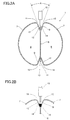
- the metallic plate whose thickness is about 0.6 through 1.2 mm, for example, is bent so as to have a central partition plate or wall 6 which extends in a diametrical direction and is elongated in a longitudinal direction throughout the exhaust pipe 1, and two passages 8, 8 each of which is formed by the partition plate 6 and a pair of peripheral walls 7, 7 which are substantially semicircular as seen in cross section. As shown in FIG. 2A, each of the semicircular walls 7, 7 starts bending from the neighborhood of the upper and lower end portions, as seen in FIG.
- target 13 denotes a portion or member which serves the function of a welding wire or a filler wire in arc welding.
- the two inclined portions 9, 12 thus form a substantially V-shaped valley or groove 14 on each diametrically opposite ends of the partition plate 6.
- the V-shaped groove 14 has a closed, or substantially closed, end on the radially inner side and an open end on the radially outer side.
- the angle "A" of the V-shaped groove 14 is about 40°, and the target 13 extends radially outward from a substantially closed end (i.e., radially inner end of the groove 14) radially outward along a line which evenly divides the groove 14 into half.
- a welding gun 15 equipped with a welding electrode or a plasma electrode is disposed on the side of the open end of the groove 14 off from (or out of contact with) the target 13 such that the welding gun points to the target 13.
- the welding gun 15 is moved in the longitudinal direction along the target 13 (i.e., in the longitudinal direction of the exhaust pipe 1) while generating a welding arc between the target 13 and the welding gun 15.
- the target 13 and the portion which lies in the neighborhood of the target 13 are thus melted together to thereby form welding bead 16 along the bottom of the groove 14 as shown in FIG. 2B.
- the welding of one diametrically outer side is finished, the welding of the other groove on the diametrically opposite side is similarly welded.
- the target 13 can thus be seen to function as a welding wire.
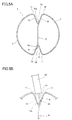
- a target 13a is formed by doubly folding a diametrically outer end portion of the partition plate 6 substantially into a U or V shape such that a closed end of the U or V shape faces radially outward in the groove.
- the target 13a is thus formed so as to extend substantially radially outward from the closed end on the radially inner side of the groove 14.
- FIG. 4 Another modified example is shown in FIG. 4.
- a target 13b is formed by inserting an independent metallic member (piece) in a clearance at the substantially closed end of the groove 14.
- the target 13b is thus formed so as to extend substantially radially outward from the substantially closed end on the radially inner side of the groove 14.
- FIG. 5A Still further example of the target portion is shown in FIG. 5A.
- the overall arrangement of the exhaust pipe is substantially the same as that shown in FIG. 2A, the only difference being that a target 13c is arranged to lie along the inclined portion 9 toward the radially outer side.
- the welding gun 15 is arranged to generate a welding arc between the tip of the gun and the front end portion of the target 13c to thereby form a welding bead 16'.
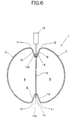
- Still another modified example of a target 13d is formed as a part of the partition plate 6 as shown in FIG. 6.
- each of the diametrically outer ends of the partition plate 6 is arranged to extend beyond the substantially closed bottom end of the groove 14, whereby a portion 13c corresponding to a target is formed in a manner substantially similar to that of the above-described examples in FIGS. 2A, 3 and 4.
- the exhaust pipe 1 is formed not by a single piece of metallic plate but is formed by three pieces.
- a semicircular wall portions 7, 7 are formed in a manner symmetrical to each other with both ends being further bent radially inward. They are then placed to face each other such that a substantially closed bottom end is formed by the diametrically inner sides of the bent ends.
- a partition plate 6 is disposed between the inclined portions 9, 12 / 9, 12 through the substantially closed radially inner side of the groove 14.
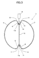
- the exhaust pipe of two-passage construction according to the present invention is shown in FIG. 7.
- the construction is basically the same as that shown in FIG. 2A or the like except for the way of connecting the diametrically outer ends of the partition plate 6 (i.e., the portion at the closed bottom end of each groove 14) and both free ends of the metallic plate (i.e., the radially inner end of each free end).
- the target which is an essential element in the above-described examples may, or may not, be employed in this particular example. Therefore, no detailed explanation will be made about the construction that is substantially the same as those of the above-described examples, by attaching the same numerals to the same or similar portions.
- the bottom of the groove 14 may be connected together by a suitable means, such as by welding, to thereby form a connecting portion 17, 17.
- the imaginary inner diameter of the exhaust pipe of two-passage construction is D.
- the depth of the groove 14, i.e., the distance from the line of the imaginary inner diameter D to the connecting portion 17 is defined to be L.
- the distance between the outer portions 10, 11 of the curves at the diametrically outer ends of the groove 14 are defined to be W.
- the depth from the diametrically outer ends of the groove 14 to the connecting portion 17 is defined to be j.
- the area of the partition plate 6 of receiving pressure thus becomes smaller and consequently the total pressure to be operated onto the partition plate 6 becomes smaller.
- the bending in the neighborhood of the connected points of contact becomes smaller and, further, the wall portions in the groove 14 also allows to bend to some degree as shown by imaginary lines in FIG. 7. As a consequence, the bending stresses and stress concentration in the neighborhood of the connected points 17, 17 are alleviated, with the result that the durability of the partition plate 6 is increased.
- the inclined portions 9, 9 and bent portions 10, 10, which together form the respective grooves 14, 14, shall preferably be arranged as follows. Namely, the inclined portions 9, 9 are formed into a plane (i.e., having a relatively straight line), and the bent portions 10, 10 are formed into curved portions which do not form the continuation of the inclined and straight portions 9, 9, which is different from continuously formed curved portions 9a, 12a as shown by imaginary lines in FIG. 7. In this arrangement, the cross-sectional area of the exhaust-gas flow can be kept larger.
- the central wall 6 may be formed in a thicker plate than the remaining portion of the exhaust pipe. According to this arrangement, a higher bending rigidity can be secured in the central portion of the partition plate 6. The deflection of the partition plate 6 is thus reduced and the stresses can accordingly be reduced.
- a plurality of reinforcing ribs 18 may be disposed on the partition plate 6 at a longitudinal distance from each other. According to this arrangement, the bending rigidity of the partition plate 6 in the diametrical direction of the partition plate can be increased. As a consequence, the deflection of the partition plate is reduced and the stresses can also be reduced.
- These reinforcing ribs 18 shall preferably be formed on the relevant portions of the partition plate 6 before the exhaust pipe is subjected to the bending work.
- FIG. 10 is a graph showing the stresses which occur at the connected points 16, 16 with varying distance L. It can be seen from this graph that a large depth L can reduce the stresses as compared with the example in which the distance L is made substantially zero (as in the conventional example in FIG. 11).
- the groove in this example is formed such that each of the connected points 16, 16 lies radially inward of the imaginary line of an inner circumference of the wall (i.e., inside the line of diameter D) and that the groove satisfies a condition of j/W ⁇ 2, most preferably, 0.5 ⁇ j/W ⁇ 2.
- the depth of the groove 14 shall preferably be made 5% or more of the imaginary inner diameter D, i.e., is formed to meet the condition of L/D ⁇ 0.05.
- the stresses in the neighborhood of the connected portions 17, 17 can surely be reduced.
- the thickness of the metallic plate to be used as the exhaust pipe can be made smaller in thickness, resulting in a smaller weight of the exhaust pipe. Therefore, when the engine is started, the exhaust pipe rapidly rises in temperature and the exhaust gases of high temperature can be sent to the catalyst converter in a shorter period of time.
- a stainless steel defined by JIS, Japanese Industrial Standard, as SUS 430
- SUS 430 Japanese Industrial Standard
- the time in which the inlet portion of the catalyst converter reaches a catalyst active temperature is "x" seconds with the plate thickness of "t.” Then, the time was found to be 0.9x second with the plate thickness of 0.8t and 0.77x second with the plate thickness of 0.6t. As can be seen from these figures, the catalyst converter can be activated at a shorter time, resulting in an improvement of the exhaust gas purifying capacity.
Landscapes
- Engineering & Computer Science (AREA)
- Mechanical Engineering (AREA)
- General Engineering & Computer Science (AREA)
- Chemical & Material Sciences (AREA)
- Combustion & Propulsion (AREA)
- Exhaust Silencers (AREA)
- Butt Welding And Welding Of Specific Article (AREA)
Priority Applications (1)
| Application Number | Priority Date | Filing Date | Title |
|---|---|---|---|
| EP02028807A EP1316384B1 (fr) | 1999-12-24 | 2000-12-22 | Méthode de fabrication d'un tuyau d'échappement ayant deux passages et tuyau d'échappement ayant deux passages |
Applications Claiming Priority (6)
| Application Number | Priority Date | Filing Date | Title |
|---|---|---|---|
| JP36674999A JP3447637B2 (ja) | 1999-12-24 | 1999-12-24 | 板部材の接続方法及び2通路管の製造方法 |
| JP36674999 | 1999-12-24 | ||
| JP2000107839 | 2000-04-10 | ||
| JP2000107839 | 2000-04-10 | ||
| JP2000204895 | 2000-07-06 | ||
| JP2000204895A JP3388726B2 (ja) | 2000-07-06 | 2000-07-06 | 2通路排気管及びその製造方法 |
Related Child Applications (1)
| Application Number | Title | Priority Date | Filing Date |
|---|---|---|---|
| EP02028807A Division EP1316384B1 (fr) | 1999-12-24 | 2000-12-22 | Méthode de fabrication d'un tuyau d'échappement ayant deux passages et tuyau d'échappement ayant deux passages |
Publications (2)
| Publication Number | Publication Date |
|---|---|
| EP1114690A1 true EP1114690A1 (fr) | 2001-07-11 |
| EP1114690B1 EP1114690B1 (fr) | 2003-09-24 |
Family
ID=27341737
Family Applications (2)
| Application Number | Title | Priority Date | Filing Date |
|---|---|---|---|
| EP02028807A Expired - Lifetime EP1316384B1 (fr) | 1999-12-24 | 2000-12-22 | Méthode de fabrication d'un tuyau d'échappement ayant deux passages et tuyau d'échappement ayant deux passages |
| EP00128272A Expired - Lifetime EP1114690B1 (fr) | 1999-12-24 | 2000-12-22 | Méthode de fabrication d'un tuyau d'échappement ayant deux passages |
Family Applications Before (1)
| Application Number | Title | Priority Date | Filing Date |
|---|---|---|---|
| EP02028807A Expired - Lifetime EP1316384B1 (fr) | 1999-12-24 | 2000-12-22 | Méthode de fabrication d'un tuyau d'échappement ayant deux passages et tuyau d'échappement ayant deux passages |
Country Status (4)
| Country | Link |
|---|---|
| US (2) | US6575198B2 (fr) |
| EP (2) | EP1316384B1 (fr) |
| CA (1) | CA2328804C (fr) |
| DE (2) | DE60015195T2 (fr) |
Cited By (4)
| Publication number | Priority date | Publication date | Assignee | Title |
|---|---|---|---|---|
| US6575198B2 (en) | 1999-12-24 | 2003-06-10 | Kabushiki Kaisha Yutaka Giken | Method of connecting two elongated portions of metallic plate, method of manufacturing exhaust pipe of two-passage construction, and exhaust pipe of two-passage construction |
| KR101069728B1 (ko) * | 2010-10-27 | 2011-10-05 | 허노훈 | 난방용 배관 어셈블리 |
| CN104959790A (zh) * | 2015-07-02 | 2015-10-07 | 广船国际有限公司 | 一种弯曲管的加工工艺 |
| EP2117745B1 (fr) * | 2007-01-15 | 2020-03-04 | FFT Produktionssysteme GmbH & Co. KG | Assemblage de tôles, procédé d'assemblage de tôles et dispositif d'assemblage |
Families Citing this family (34)
| Publication number | Priority date | Publication date | Assignee | Title |
|---|---|---|---|---|
| US6415889B1 (en) * | 1998-01-30 | 2002-07-09 | Arvinmeritor, Inc. | Stamped-formed muffler apparatus and assembly process |
| BE1014254A3 (fr) * | 2001-06-20 | 2003-07-01 | Sonaca Sa | Structure tubulaire mince cloisonnee et son procede de fabrication. |
| US7086497B2 (en) * | 2001-09-27 | 2006-08-08 | Siemens Vdo Automotive Inc. | Induction system with low pass filter for turbo charger applications |
| US7409963B2 (en) * | 2004-11-05 | 2008-08-12 | Go Papa, Lllp | Corner molding and stop assembly for collapsible shelter |
| JP4760287B2 (ja) * | 2005-10-13 | 2011-08-31 | 日産自動車株式会社 | 内燃機関の排気装置 |
| USD573520S1 (en) * | 2006-09-15 | 2008-07-22 | Kawasaki Jukogyo Kabushiki Kaisha | Motorcycle muffler |
| USD575213S1 (en) * | 2007-09-19 | 2008-08-19 | Kooks Custom Headers, Inc. | Quad core muffler |
| FR2924752B1 (fr) * | 2007-12-05 | 2015-09-18 | Renault Sas | Collecteur d'echappement en tole mince pour moteur a combustion interne |
| US8608532B2 (en) * | 2008-04-23 | 2013-12-17 | Ford Global Technologies, Llc | Climate control duct architecture for a vehicle |
| USD641676S1 (en) * | 2008-10-29 | 2011-07-19 | Shawna Cannon Lemon | Exhaust pipe set for a mini van |
| USD612313S1 (en) * | 2009-01-27 | 2010-03-23 | Brock Davidson Enterprises | Motorcycle megaphone exhaust system discharge opening |
| DE102009048407B4 (de) * | 2009-10-06 | 2012-11-15 | Tenneco Gmbh | Abgasanlage |
| US8186386B2 (en) * | 2009-10-23 | 2012-05-29 | Butler Boyd L | Modular exhaust tube system |
| RU2595706C2 (ru) | 2010-09-23 | 2016-08-27 | Шэйп Корп. | Установка и способ для изготовления трубчатой балки с одной центральной секцией |
| PL2479398T3 (pl) * | 2011-01-25 | 2017-10-31 | Joseph Voegele Ag | Wykańczarka albo zasilacz |
| CA2770876C (fr) | 2012-03-08 | 2018-02-27 | Abc Canada Technology Group Ltd. | Tube tisse soude a double voie |
| JP5811946B2 (ja) * | 2012-05-16 | 2015-11-11 | 株式会社オートネットワーク技術研究所 | ワイヤハーネス |
| US9533343B2 (en) * | 2014-06-12 | 2017-01-03 | Ford Global Technologies, Llc | Aluminum porthole extruded tubing with locating feature |
| JP6599862B2 (ja) * | 2014-07-11 | 2019-10-30 | 倉敷紡績株式会社 | 曲げ加工品 |
| CN105065102B (zh) * | 2015-07-21 | 2017-10-20 | 力帆实业(集团)股份有限公司 | 排气管安装结构以及摩托车 |
| CN106482568B (zh) * | 2015-08-25 | 2019-03-12 | 丹佛斯微通道换热器(嘉兴)有限公司 | 用于换热器的换热管、换热器及其装配方法 |
| JP6804754B2 (ja) * | 2016-09-30 | 2020-12-23 | 内山工業株式会社 | 管状体 |
| FR3065488B1 (fr) * | 2017-04-20 | 2019-06-28 | Faurecia Systemes D'echappement | Element de ligne d'echappement et procede de fabrication d'un tel element |
| US10906080B2 (en) | 2018-04-16 | 2021-02-02 | Ford Motor Company | System and methods to radially orient extruded tubing for vehicle body component |
| US10753266B2 (en) * | 2018-05-16 | 2020-08-25 | GM Global Technology Operations LLC | J-groove for crack suppression |
| US11427144B2 (en) | 2018-11-27 | 2022-08-30 | Shape Corp. | Galvanized multi-tubular beam and method of continuously forming the same |
| USD955249S1 (en) * | 2020-06-29 | 2022-06-21 | Powerhouse Engine Solutions Switzerland IP Holding GmbH | Leak detection apparatus |
| USD955250S1 (en) * | 2020-07-07 | 2022-06-21 | Powerhouse Engine Solutions Switzerland IP Holding GmbH | Leak detection apparatus |
| US12391200B2 (en) | 2021-08-30 | 2025-08-19 | Shape Corp. | Multi-tubular beam with forged weld seam |
| USD1022156S1 (en) * | 2021-10-05 | 2024-04-09 | Industrial Flow Solutions Operating, Llc | Pipe for fluid distribution |
| USD1022153S1 (en) * | 2021-10-05 | 2024-04-09 | Industrial Flow Solutions Operating Llc | Pipe for fluid distribution |
| USD1022155S1 (en) * | 2021-10-05 | 2024-04-09 | Industrial Flow Solutions Operating Llc | Pipe for fluid distribution |
| USD1022157S1 (en) * | 2021-10-05 | 2024-04-09 | Industrial Flow Solutions Operating, Llc | Pipe for fluid distribution |
| USD1023252S1 (en) * | 2021-10-05 | 2024-04-16 | Industrial Flow Solutions Operating, Llc | Pipe for fluid distribution |
Citations (10)
| Publication number | Priority date | Publication date | Assignee | Title |
|---|---|---|---|---|
| US2515179A (en) * | 1946-10-29 | 1950-07-18 | American Can Co | Method of producing container bodies |
| FR974863A (fr) * | 1948-11-12 | 1951-02-27 | Cie Des Echangeurs De Chaleur | Perfectionnements à la fabrication des tubes d'échangeur de chaleur |
| US3140385A (en) * | 1961-09-01 | 1964-07-07 | Charles W Johnston | Arc welding and filler rod shape |
| US3625258A (en) * | 1970-03-16 | 1971-12-07 | Warren Petroleum Corp | Multipassage pipe |
| US4460118A (en) * | 1981-05-29 | 1984-07-17 | Nippon Steel Corporation | Method for forming electric welded pipe |
| US4633056A (en) * | 1983-06-14 | 1986-12-30 | Mtu Muenchen Gmbh | Method for manufacturing special-section tubes for tubular heat exchangers and tubes provided by such method |
| FR2636253A1 (fr) * | 1988-09-09 | 1990-03-16 | Luchaire Sa | Tube cloisonne longitudinalement constitue d'un feuillard d'un seul tenant et son procede de fabrication |
| WO1990007392A1 (fr) * | 1989-01-03 | 1990-07-12 | Ortic Ab | Procede de fabrication de tuyaux carres a partir de feuillards d'acier a surface enduite |
| JPH09192727A (ja) * | 1996-01-16 | 1997-07-29 | Futaba Sangyo Kk | 流路分割パイプ及び二重管型排気パイプ |
| DE19623103A1 (de) * | 1996-06-10 | 1997-12-11 | Ymos Ag Ind Produkte | Verfahren zur Herstellung einer T-Verbindung durch Schweißen sowie Profil und Schweißplättchen zur Durchführung des Verfahrens |
Family Cites Families (9)
| Publication number | Priority date | Publication date | Assignee | Title |
|---|---|---|---|---|
| US2655181A (en) * | 1949-09-14 | 1953-10-13 | Mccord Corp | Tube construction |
| US3110754A (en) * | 1960-05-11 | 1963-11-12 | William W Witort | Conduit system and components therefor |
| US5186251A (en) * | 1992-06-01 | 1993-02-16 | General Motors Corporation | Roll formed heat exchanger tubing with double row flow passes |
| JP3546981B2 (ja) * | 1996-04-30 | 2004-07-28 | カルソニックカンセイ株式会社 | 管体の接続構造 |
| US5956846A (en) * | 1997-03-21 | 1999-09-28 | Livernois Research & Development Co. | Method and apparatus for controlled atmosphere brazing of unwelded tubes |
| JPH1191352A (ja) * | 1997-09-24 | 1999-04-06 | Sanyo Mach Works Ltd | インパクトバーおよびその製造方法 |
| DE29816479U1 (de) * | 1998-09-15 | 1998-12-24 | Adam Opel AG, 65428 Rüsselsheim | Zweiflutiges Rohr, insbesondere für Abgasanlagen von Brennkraftmaschinen |
| CA2322920C (fr) * | 1999-10-08 | 2006-05-23 | Kabushiki Kaisha Yutaka Giken | Tuyau d'echappement a deux passages |
| CA2328804C (fr) * | 1999-12-24 | 2009-07-07 | Kabushiki Kaisha Yutaka Giken | Methode pour connecter deux portions allongees de plaque metallique, methode pour fabriquer un tuyau d'echappement a deux passages, et tuyau d'echappement a deux passages |
-
2000
- 2000-12-19 CA CA002328804A patent/CA2328804C/fr not_active Expired - Fee Related
- 2000-12-22 DE DE60015195T patent/DE60015195T2/de not_active Expired - Lifetime
- 2000-12-22 US US09/742,280 patent/US6575198B2/en not_active Expired - Fee Related
- 2000-12-22 DE DE60005476T patent/DE60005476T2/de not_active Expired - Lifetime
- 2000-12-22 EP EP02028807A patent/EP1316384B1/fr not_active Expired - Lifetime
- 2000-12-22 EP EP00128272A patent/EP1114690B1/fr not_active Expired - Lifetime
-
2003
- 2003-03-26 US US10/396,478 patent/US20030163918A1/en not_active Abandoned
Patent Citations (10)
| Publication number | Priority date | Publication date | Assignee | Title |
|---|---|---|---|---|
| US2515179A (en) * | 1946-10-29 | 1950-07-18 | American Can Co | Method of producing container bodies |
| FR974863A (fr) * | 1948-11-12 | 1951-02-27 | Cie Des Echangeurs De Chaleur | Perfectionnements à la fabrication des tubes d'échangeur de chaleur |
| US3140385A (en) * | 1961-09-01 | 1964-07-07 | Charles W Johnston | Arc welding and filler rod shape |
| US3625258A (en) * | 1970-03-16 | 1971-12-07 | Warren Petroleum Corp | Multipassage pipe |
| US4460118A (en) * | 1981-05-29 | 1984-07-17 | Nippon Steel Corporation | Method for forming electric welded pipe |
| US4633056A (en) * | 1983-06-14 | 1986-12-30 | Mtu Muenchen Gmbh | Method for manufacturing special-section tubes for tubular heat exchangers and tubes provided by such method |
| FR2636253A1 (fr) * | 1988-09-09 | 1990-03-16 | Luchaire Sa | Tube cloisonne longitudinalement constitue d'un feuillard d'un seul tenant et son procede de fabrication |
| WO1990007392A1 (fr) * | 1989-01-03 | 1990-07-12 | Ortic Ab | Procede de fabrication de tuyaux carres a partir de feuillards d'acier a surface enduite |
| JPH09192727A (ja) * | 1996-01-16 | 1997-07-29 | Futaba Sangyo Kk | 流路分割パイプ及び二重管型排気パイプ |
| DE19623103A1 (de) * | 1996-06-10 | 1997-12-11 | Ymos Ag Ind Produkte | Verfahren zur Herstellung einer T-Verbindung durch Schweißen sowie Profil und Schweißplättchen zur Durchführung des Verfahrens |
Non-Patent Citations (1)
| Title |
|---|
| PATENT ABSTRACTS OF JAPAN vol. 1997, no. 11 28 November 1997 (1997-11-28) * |
Cited By (5)
| Publication number | Priority date | Publication date | Assignee | Title |
|---|---|---|---|---|
| US6575198B2 (en) | 1999-12-24 | 2003-06-10 | Kabushiki Kaisha Yutaka Giken | Method of connecting two elongated portions of metallic plate, method of manufacturing exhaust pipe of two-passage construction, and exhaust pipe of two-passage construction |
| EP2117745B1 (fr) * | 2007-01-15 | 2020-03-04 | FFT Produktionssysteme GmbH & Co. KG | Assemblage de tôles, procédé d'assemblage de tôles et dispositif d'assemblage |
| KR101069728B1 (ko) * | 2010-10-27 | 2011-10-05 | 허노훈 | 난방용 배관 어셈블리 |
| CN104959790A (zh) * | 2015-07-02 | 2015-10-07 | 广船国际有限公司 | 一种弯曲管的加工工艺 |
| CN104959790B (zh) * | 2015-07-02 | 2017-06-06 | 广船国际有限公司 | 一种弯曲管的加工工艺 |
Also Published As
| Publication number | Publication date |
|---|---|
| DE60015195D1 (de) | 2004-11-25 |
| EP1316384A3 (fr) | 2003-06-11 |
| DE60015195T2 (de) | 2005-08-25 |
| EP1114690B1 (fr) | 2003-09-24 |
| DE60005476T2 (de) | 2004-07-01 |
| EP1316384B1 (fr) | 2004-10-20 |
| CA2328804A1 (fr) | 2001-06-24 |
| CA2328804C (fr) | 2009-07-07 |
| DE60005476D1 (de) | 2003-10-30 |
| US6575198B2 (en) | 2003-06-10 |
| EP1316384A2 (fr) | 2003-06-04 |
| US20010037836A1 (en) | 2001-11-08 |
| US20030163918A1 (en) | 2003-09-04 |
Similar Documents
| Publication | Publication Date | Title |
|---|---|---|
| US6575198B2 (en) | Method of connecting two elongated portions of metallic plate, method of manufacturing exhaust pipe of two-passage construction, and exhaust pipe of two-passage construction | |
| EP1039106B1 (fr) | Arrangement d'une portion d'assemblage de branches de collecteur d'échappement | |
| US7770937B2 (en) | Stepped ball joint pipe clamp and pre-attachment components therefor | |
| US5020631A (en) | Modular silencer | |
| GB2294500A (en) | I.c.engine exhaust silencer | |
| JP3546981B2 (ja) | 管体の接続構造 | |
| WO2017132649A1 (fr) | Raccord de silencieux | |
| JP2008064090A (ja) | 排気浄化構成要素用のハウジング | |
| US10087808B2 (en) | Exhaust system with tailored wall thickness | |
| JP2531644Y2 (ja) | 車輌用排気系フランジ継手 | |
| JP3402224B2 (ja) | 内燃機関用排気管及びその仕切板溶接方法 | |
| JP2002206422A (ja) | マフラ用シェル | |
| EP0950460B1 (fr) | Méthode de fabrication de l'enceinte d'un silencieux d'échappement, et enceinte fabriquée | |
| KR100295580B1 (ko) | 촉매용벌집형체구조 | |
| JP2000356294A (ja) | ベンド管の製造方法 | |
| JP4188057B2 (ja) | 消音器とその製造方法 | |
| US20040168320A1 (en) | Plate and tube join and method | |
| JPH05146685A (ja) | 排気ガス浄化用触媒及びその製造方法 | |
| US20020116819A1 (en) | Method of making an exhaust gas collector | |
| JP3960202B2 (ja) | 内燃機関の排気系構成部品の接合構造 | |
| JP2670966B2 (ja) | 筒体の継ぎ手 | |
| JP3199630U (ja) | 内燃機関用消音器 | |
| JP2007239537A (ja) | 排気管フランジ継手構造 | |
| JP4069910B2 (ja) | エキゾーストマニホルド集合部構造 | |
| JP4110944B2 (ja) | 蛇腹管の溶接構造 |
Legal Events
| Date | Code | Title | Description |
|---|---|---|---|
| PUAI | Public reference made under article 153(3) epc to a published international application that has entered the european phase |
Free format text: ORIGINAL CODE: 0009012 |
|
| AK | Designated contracting states |
Kind code of ref document: A1 Designated state(s): DE FR GB |
|
| AX | Request for extension of the european patent |
Free format text: AL;LT;LV;MK;RO;SI |
|
| 17P | Request for examination filed |
Effective date: 20010622 |
|
| 17Q | First examination report despatched |
Effective date: 20011203 |
|
| AKX | Designation fees paid |
Free format text: DE FR GB |
|
| GRAH | Despatch of communication of intention to grant a patent |
Free format text: ORIGINAL CODE: EPIDOS IGRA |
|
| RTI1 | Title (correction) |
Free format text: METHOD OF MANUFACTURING EXHAUST PIPE OF TWO-PASSAGE CONSTRUCTION |
|
| GRAS | Grant fee paid |
Free format text: ORIGINAL CODE: EPIDOSNIGR3 |
|
| GRAA | (expected) grant |
Free format text: ORIGINAL CODE: 0009210 |
|
| AK | Designated contracting states |
Kind code of ref document: B1 Designated state(s): DE FR GB |
|
| REG | Reference to a national code |
Ref country code: GB Ref legal event code: FG4D |
|
| REF | Corresponds to: |
Ref document number: 60005476 Country of ref document: DE Date of ref document: 20031030 Kind code of ref document: P |
|
| ET | Fr: translation filed | ||
| PLBE | No opposition filed within time limit |
Free format text: ORIGINAL CODE: 0009261 |
|
| STAA | Information on the status of an ep patent application or granted ep patent |
Free format text: STATUS: NO OPPOSITION FILED WITHIN TIME LIMIT |
|
| 26N | No opposition filed |
Effective date: 20040625 |
|
| PGFP | Annual fee paid to national office [announced via postgrant information from national office to epo] |
Ref country code: GB Payment date: 20071221 Year of fee payment: 8 |
|
| PGFP | Annual fee paid to national office [announced via postgrant information from national office to epo] |
Ref country code: FR Payment date: 20071221 Year of fee payment: 8 |
|
| GBPC | Gb: european patent ceased through non-payment of renewal fee |
Effective date: 20081222 |
|
| REG | Reference to a national code |
Ref country code: FR Ref legal event code: ST Effective date: 20090831 |
|
| PG25 | Lapsed in a contracting state [announced via postgrant information from national office to epo] |
Ref country code: GB Free format text: LAPSE BECAUSE OF NON-PAYMENT OF DUE FEES Effective date: 20081222 |
|
| PG25 | Lapsed in a contracting state [announced via postgrant information from national office to epo] |
Ref country code: FR Free format text: LAPSE BECAUSE OF NON-PAYMENT OF DUE FEES Effective date: 20081231 |
|
| PGFP | Annual fee paid to national office [announced via postgrant information from national office to epo] |
Ref country code: DE Payment date: 20100226 Year of fee payment: 10 |
|
| REG | Reference to a national code |
Ref country code: DE Ref legal event code: R119 Ref document number: 60005476 Country of ref document: DE Effective date: 20110701 |
|
| PG25 | Lapsed in a contracting state [announced via postgrant information from national office to epo] |
Ref country code: DE Free format text: LAPSE BECAUSE OF NON-PAYMENT OF DUE FEES Effective date: 20110701 |