EP1116970A1 - Optische übertragungsstrecke - Google Patents
Optische übertragungsstrecke Download PDFInfo
- Publication number
- EP1116970A1 EP1116970A1 EP00940849A EP00940849A EP1116970A1 EP 1116970 A1 EP1116970 A1 EP 1116970A1 EP 00940849 A EP00940849 A EP 00940849A EP 00940849 A EP00940849 A EP 00940849A EP 1116970 A1 EP1116970 A1 EP 1116970A1
- Authority
- EP
- European Patent Office
- Prior art keywords
- optical fiber
- core
- refractive index
- side core
- covering
- Prior art date
- Legal status (The legal status is an assumption and is not a legal conclusion. Google has not performed a legal analysis and makes no representation as to the accuracy of the status listed.)
- Withdrawn
Links
Images


Classifications
-
- G—PHYSICS
- G02—OPTICS
- G02B—OPTICAL ELEMENTS, SYSTEMS OR APPARATUS
- G02B6/00—Light guides; Structural details of arrangements comprising light guides and other optical elements, e.g. couplings
- G02B6/02—Optical fibres with cladding with or without a coating
- G02B6/02004—Optical fibres with cladding with or without a coating characterised by the core effective area or mode field radius
- G02B6/02009—Large effective area or mode field radius, e.g. to reduce nonlinear effects in single mode fibres
-
- G—PHYSICS
- G02—OPTICS
- G02B—OPTICAL ELEMENTS, SYSTEMS OR APPARATUS
- G02B6/00—Light guides; Structural details of arrangements comprising light guides and other optical elements, e.g. couplings
- G02B6/02—Optical fibres with cladding with or without a coating
- G02B6/02214—Optical fibres with cladding with or without a coating tailored to obtain the desired dispersion, e.g. dispersion shifted, dispersion flattened
- G02B6/02219—Characterised by the wavelength dispersion properties in the silica low loss window around 1550 nm, i.e. S, C, L and U bands from 1460-1675 nm
- G02B6/02252—Negative dispersion fibres at 1550 nm
- G02B6/02261—Dispersion compensating fibres, i.e. for compensating positive dispersion of other fibres
-
- G—PHYSICS
- G02—OPTICS
- G02B—OPTICAL ELEMENTS, SYSTEMS OR APPARATUS
- G02B6/00—Light guides; Structural details of arrangements comprising light guides and other optical elements, e.g. couplings
- G02B6/02—Optical fibres with cladding with or without a coating
- G02B6/02214—Optical fibres with cladding with or without a coating tailored to obtain the desired dispersion, e.g. dispersion shifted, dispersion flattened
- G02B6/02219—Characterised by the wavelength dispersion properties in the silica low loss window around 1550 nm, i.e. S, C, L and U bands from 1460-1675 nm
- G02B6/02266—Positive dispersion fibres at 1550 nm
- G02B6/02271—Non-zero dispersion shifted fibres, i.e. having a small positive dispersion at 1550 nm, e.g. ITU-T G.655 dispersion between 1.0 to 10 ps/nm.km for avoiding nonlinear effects
-
- G—PHYSICS
- G02—OPTICS
- G02B—OPTICAL ELEMENTS, SYSTEMS OR APPARATUS
- G02B6/00—Light guides; Structural details of arrangements comprising light guides and other optical elements, e.g. couplings
- G02B6/02—Optical fibres with cladding with or without a coating
- G02B6/02214—Optical fibres with cladding with or without a coating tailored to obtain the desired dispersion, e.g. dispersion shifted, dispersion flattened
- G02B6/02219—Characterised by the wavelength dispersion properties in the silica low loss window around 1550 nm, i.e. S, C, L and U bands from 1460-1675 nm
- G02B6/02276—Dispersion shifted fibres, i.e. zero dispersion at 1550 nm
-
- G—PHYSICS
- G02—OPTICS
- G02B—OPTICAL ELEMENTS, SYSTEMS OR APPARATUS
- G02B6/00—Light guides; Structural details of arrangements comprising light guides and other optical elements, e.g. couplings
- G02B6/02—Optical fibres with cladding with or without a coating
- G02B6/028—Optical fibres with cladding with or without a coating with core or cladding having graded refractive index
- G02B6/0281—Graded index region forming part of the central core segment, e.g. alpha profile, triangular, trapezoidal core
-
- G—PHYSICS
- G02—OPTICS
- G02B—OPTICAL ELEMENTS, SYSTEMS OR APPARATUS
- G02B6/00—Light guides; Structural details of arrangements comprising light guides and other optical elements, e.g. couplings
- G02B6/02—Optical fibres with cladding with or without a coating
- G02B6/036—Optical fibres with cladding with or without a coating core or cladding comprising multiple layers
- G02B6/03605—Highest refractive index not on central axis
- G02B6/03611—Highest index adjacent to central axis region, e.g. annular core, coaxial ring, centreline depression affecting waveguiding
-
- G—PHYSICS
- G02—OPTICS
- G02B—OPTICAL ELEMENTS, SYSTEMS OR APPARATUS
- G02B6/00—Light guides; Structural details of arrangements comprising light guides and other optical elements, e.g. couplings
- G02B6/02—Optical fibres with cladding with or without a coating
- G02B6/036—Optical fibres with cladding with or without a coating core or cladding comprising multiple layers
- G02B6/03616—Optical fibres characterised both by the number of different refractive index layers around the central core segment, i.e. around the innermost high index core layer, and their relative refractive index difference
- G02B6/03622—Optical fibres characterised both by the number of different refractive index layers around the central core segment, i.e. around the innermost high index core layer, and their relative refractive index difference having 2 layers only
- G02B6/03627—Optical fibres characterised both by the number of different refractive index layers around the central core segment, i.e. around the innermost high index core layer, and their relative refractive index difference having 2 layers only arranged - +
-
- G—PHYSICS
- G02—OPTICS
- G02B—OPTICAL ELEMENTS, SYSTEMS OR APPARATUS
- G02B6/00—Light guides; Structural details of arrangements comprising light guides and other optical elements, e.g. couplings
- G02B6/02—Optical fibres with cladding with or without a coating
- G02B6/036—Optical fibres with cladding with or without a coating core or cladding comprising multiple layers
- G02B6/03616—Optical fibres characterised both by the number of different refractive index layers around the central core segment, i.e. around the innermost high index core layer, and their relative refractive index difference
- G02B6/03622—Optical fibres characterised both by the number of different refractive index layers around the central core segment, i.e. around the innermost high index core layer, and their relative refractive index difference having 2 layers only
- G02B6/03633—Optical fibres characterised both by the number of different refractive index layers around the central core segment, i.e. around the innermost high index core layer, and their relative refractive index difference having 2 layers only arranged - -
-
- G—PHYSICS
- G02—OPTICS
- G02B—OPTICAL ELEMENTS, SYSTEMS OR APPARATUS
- G02B6/00—Light guides; Structural details of arrangements comprising light guides and other optical elements, e.g. couplings
- G02B6/02—Optical fibres with cladding with or without a coating
- G02B6/036—Optical fibres with cladding with or without a coating core or cladding comprising multiple layers
- G02B6/03616—Optical fibres characterised both by the number of different refractive index layers around the central core segment, i.e. around the innermost high index core layer, and their relative refractive index difference
- G02B6/03638—Optical fibres characterised both by the number of different refractive index layers around the central core segment, i.e. around the innermost high index core layer, and their relative refractive index difference having 3 layers only
- G02B6/03644—Optical fibres characterised both by the number of different refractive index layers around the central core segment, i.e. around the innermost high index core layer, and their relative refractive index difference having 3 layers only arranged - + -
-
- G—PHYSICS
- G02—OPTICS
- G02B—OPTICAL ELEMENTS, SYSTEMS OR APPARATUS
- G02B6/00—Light guides; Structural details of arrangements comprising light guides and other optical elements, e.g. couplings
- G02B6/24—Coupling light guides
- G02B6/26—Optical coupling means
- G02B6/28—Optical coupling means having data bus means, i.e. plural waveguides interconnected and providing an inherently bidirectional system by mixing and splitting signals
- G02B6/293—Optical coupling means having data bus means, i.e. plural waveguides interconnected and providing an inherently bidirectional system by mixing and splitting signals with wavelength selective means
- G02B6/29371—Optical coupling means having data bus means, i.e. plural waveguides interconnected and providing an inherently bidirectional system by mixing and splitting signals with wavelength selective means operating principle based on material dispersion
- G02B6/29374—Optical coupling means having data bus means, i.e. plural waveguides interconnected and providing an inherently bidirectional system by mixing and splitting signals with wavelength selective means operating principle based on material dispersion in an optical light guide
- G02B6/29376—Optical coupling means having data bus means, i.e. plural waveguides interconnected and providing an inherently bidirectional system by mixing and splitting signals with wavelength selective means operating principle based on material dispersion in an optical light guide coupling light guides for controlling wavelength dispersion, e.g. by concatenation of two light guides having different dispersion properties
- G02B6/29377—Optical coupling means having data bus means, i.e. plural waveguides interconnected and providing an inherently bidirectional system by mixing and splitting signals with wavelength selective means operating principle based on material dispersion in an optical light guide coupling light guides for controlling wavelength dispersion, e.g. by concatenation of two light guides having different dispersion properties controlling dispersion around 1550 nm, i.e. S, C, L and U bands from 1460-1675 nm
-
- H—ELECTRICITY
- H04—ELECTRIC COMMUNICATION TECHNIQUE
- H04B—TRANSMISSION
- H04B10/00—Transmission systems employing electromagnetic waves other than radio-waves, e.g. infrared, visible or ultraviolet light, or employing corpuscular radiation, e.g. quantum communication
- H04B10/25—Arrangements specific to fibre transmission
- H04B10/2507—Arrangements specific to fibre transmission for the reduction or elimination of distortion or dispersion
- H04B10/2513—Arrangements specific to fibre transmission for the reduction or elimination of distortion or dispersion due to chromatic dispersion
- H04B10/2525—Arrangements specific to fibre transmission for the reduction or elimination of distortion or dispersion due to chromatic dispersion using dispersion-compensating fibres
- H04B10/25253—Arrangements specific to fibre transmission for the reduction or elimination of distortion or dispersion due to chromatic dispersion using dispersion-compensating fibres with dispersion management, i.e. using a combination of different kind of fibres in the transmission system
-
- G—PHYSICS
- G02—OPTICS
- G02B—OPTICAL ELEMENTS, SYSTEMS OR APPARATUS
- G02B6/00—Light guides; Structural details of arrangements comprising light guides and other optical elements, e.g. couplings
- G02B6/02—Optical fibres with cladding with or without a coating
- G02B6/02004—Optical fibres with cladding with or without a coating characterised by the core effective area or mode field radius
-
- G—PHYSICS
- G02—OPTICS
- G02B—OPTICAL ELEMENTS, SYSTEMS OR APPARATUS
- G02B6/00—Light guides; Structural details of arrangements comprising light guides and other optical elements, e.g. couplings
- G02B6/02—Optical fibres with cladding with or without a coating
- G02B6/02214—Optical fibres with cladding with or without a coating tailored to obtain the desired dispersion, e.g. dispersion shifted, dispersion flattened
- G02B6/02219—Characterised by the wavelength dispersion properties in the silica low loss window around 1550 nm, i.e. S, C, L and U bands from 1460-1675 nm
- G02B6/02252—Negative dispersion fibres at 1550 nm
-
- G—PHYSICS
- G02—OPTICS
- G02B—OPTICAL ELEMENTS, SYSTEMS OR APPARATUS
- G02B6/00—Light guides; Structural details of arrangements comprising light guides and other optical elements, e.g. couplings
- G02B6/02—Optical fibres with cladding with or without a coating
- G02B6/02214—Optical fibres with cladding with or without a coating tailored to obtain the desired dispersion, e.g. dispersion shifted, dispersion flattened
- G02B6/02219—Characterised by the wavelength dispersion properties in the silica low loss window around 1550 nm, i.e. S, C, L and U bands from 1460-1675 nm
- G02B6/02266—Positive dispersion fibres at 1550 nm
-
- G—PHYSICS
- G02—OPTICS
- G02B—OPTICAL ELEMENTS, SYSTEMS OR APPARATUS
- G02B6/00—Light guides; Structural details of arrangements comprising light guides and other optical elements, e.g. couplings
- G02B6/02—Optical fibres with cladding with or without a coating
- G02B6/02214—Optical fibres with cladding with or without a coating tailored to obtain the desired dispersion, e.g. dispersion shifted, dispersion flattened
- G02B6/0228—Characterised by the wavelength dispersion slope properties around 1550 nm
-
- G—PHYSICS
- G02—OPTICS
- G02B—OPTICAL ELEMENTS, SYSTEMS OR APPARATUS
- G02B6/00—Light guides; Structural details of arrangements comprising light guides and other optical elements, e.g. couplings
- G02B6/02—Optical fibres with cladding with or without a coating
- G02B6/02214—Optical fibres with cladding with or without a coating tailored to obtain the desired dispersion, e.g. dispersion shifted, dispersion flattened
- G02B6/02285—Characterised by the polarisation mode dispersion [PMD] properties, e.g. for minimising PMD
Definitions
- the present invention relates to an optical transmission line which is used when, for example, a wavelength division multiplexed optical transmission is carried out.
- the wavelength division multiplexed transmission (WDM transmission) is widely recognized in the communication field and now the era of the wavelength division multiplexed transmission has arrived.
- WDM transmission wavelength division multiplexed transmission
- the wavelength division multiplexed transmission is an optical transmission system which is suitable for large capacity high speed communication and, at present, this transmission technology is being vigorously researched.
- a single mode optical fiber having a zero-dispersion within the wavelength band in the vicinity of the wavelength of 1.3 ⁇ m
- the transmission network for optical communication has been established on a global scale as the transmission network for optical communication.
- the previously established single mode optical fiber having a zero-dispersion in the vicinity of 1.3 ⁇ m is utilized and wavelength division multiplexed transmission is carried out by using the wavelength band in the vicinity of 1.3 ⁇ m, the 1.5 ⁇ m wavelength band, which is the gain band of a conventional optical amplifier, and the wavelength band do not agree with each other. Therefore, the problem arises that a conventional optical amplifier cannot be utilized for the wavelength division multiplexed transmission which uses the above described single mode optical fiber and, subsequently, long distance optical communication becomes difficult.
- 1.5 ⁇ m wavelength band means a wavelength band of which the center is approximately the wavelength 1550 nm, such as from 1530 nm to 1570 nm, and hereinafter the term, the 1.5 ⁇ m wavelength band, is used with this meaning.
- a dispersion shift optical fiber which controls the above described wavelength dispersion and dispersion slope and which makes it possible to lower the non-linearity phenomenon is desirable as a dispersion shift optical fiber for the wavelength division multiplexed transmission.
- the above described paper reports that control of the four light wave mixture is possible by allowing the dispersion shift optical fiber used for the optical transmission to have a microscopic dispersion at the wavelength of 1.55 ⁇ m, which is the signal light wavelength.
- the above described microscopic dispersion is a dispersion of which the absolute value of, for example, the local dispersion (a dispersion per unit length) is approximately 2 to 3 ps/nm/km.
- the distortion ⁇ NL of the signal through the non-linearity phenomenon is, in general, represented by the following equation (1). Therefore, when the effective core section area of the optical fiber is large the waveform distortion of the signal through the non-linearity phenomenon can be made small.
- ⁇ NL (2 ⁇ n 2 ⁇ L eff ⁇ P)/( ⁇ A eff )
- ⁇ represents the circular constant
- L eff represents the effective optical fiber length
- P represents a signal light intensity
- ⁇ represents a signal light wavelength, respectively.
- the above described effective core section area is expressed by the following equation (2) by using a constant k and the mode field diameter (MFD) of the optical fiber. Therefore, the larger the mode field diameter is, the larger the effective core section area becomes and it is understood that low non-linearity can be achieved very effectively.
- a eff k ⁇ (MFD) 2
- the single mode optical fiber is superior in terms of low non-linearity. Therefore, in order that this characteristic is utilized to control the waveform distortion resulting from the above described non-linearity phenomenon, a proposal is made that the optical transmission line be formed of a single mode optical fiber and a short dispersion compensation optical fiber is connected to the emission end of this optical transmission line. This proposal is made in, for example, the Japanese Unexamined Patent Publication No. Hei-6(1994)-11620, or the like. This proposal attempts to implement low non-linearity of the optical transmission line using the above described configuration and to control the wavelength dispersion of the single mode optical fiber.
- the mode field diameter within the 1.5 ⁇ m wavelength band of the dispersion compensation optical fiber becomes, in design, too small to compensate for the dispersion characteristics of the single mode optical fiber with short length, and easily causes the non-linearity phenomenon. Therefore, in the scheme of the above described Japanese Unexamined Patent Publication No. Hei-6(1994)-11620 the problem of the non-linearity phenomenon cannot be controlled.
- the above described dispersion compensation optical fiber has an extremely large absolute value of the dispersion value within the wavelength of the 1,55 ⁇ m band. Therefore, the optical transmission line formed by connecting the single mode optical fiber and the dispersion compensation optical fiber has an extremely large absolute value of local dispersion (dispersion value per unit length) on the side of the dispersion compensation optical fiber. Accordingly, this optical transmission line cannot completely control the waveform distortion resulting from the dispersion even though the wavelength dispersion of the entire optical transmission line can be made approximately zero and, therefore, there is a risk that the waveform distortion resulting from dispersion might remain.
- the dispersion value within the wavelength of 1.55 ⁇ m band of the single mode optical fiber is approximately 17 ps/nm/km and, in order to prevent the influence of a local dispersion the absolute value of the dispersion value, needs to be made even smaller.
- the dispersion shift optical fiber which has an extremely small dispersion of which the dispersion value is within ⁇ 5 ps/nm/km, is known. And this dispersion shift optical fiber cannot control the non-linearity phenomenon as described above.
- the 1.5 ⁇ m wavelength band denotes a wavelength band including the conventional 1.5 ⁇ m wavelength band, such as 1520 to 1620 nm, and hereinafter the term 1.5 ⁇ m band is used in this sense.
- the present invention is provided to solve the above described conventional problems.
- the purpose of the present invention is to provide an optical transmission line which has the characteristics as shown the following. That is to say, the purpose of the present invention is firstly, to make the dispersion of the entire optical transmission line approximately zero when the optical transmission line according to the present invention is used for the wavelength division multiplexed transmission and, secondly, to control local dispersion of the optical fiber which forms the optical transmission line and, thereby, to control the waveform distortion resulting from dispersion with almost no failure and, thirdly, to make possible a high quality signal light transmission which can control the waveform distortion resulting from the non-linearity phenomenon.
- the present invention provides the means for solving the problems with the configurations as follows: that is to say, the first configuration of the present invention is characterized in that said optical transmission line is formed by connecting, in series, a first optical fiber of which the dispersion value in the set wavelength band within the 1.5 ⁇ m wavelength band is 6 to 14 ps/nm/km and a second optical fiber of which the dispersion value in the set wavelength band within the 1.5 ⁇ m wavelength band is -14 to -6 ps/nm/km and in that the dispersion value in the set wavelength band within the 1.5 ⁇ m wavelength band is approximately zero for the entire optical transmission line.
- the second configuration of the present invention is, in addition to the above first configuration, characterized in that the closer to the input end of an optical signal the arrangement position of the optical fiber is, the lower the non-linearity of the optical fiber is.
- the third configuration of the present invention is, in addition to the above first or second configuration, characterized in that the dispersion slope of the first optical fiber is of the opposite symbol to the second optical fiber, and in that the dispersion slope in the set wavelength band within the 1.5 ⁇ m wavelength band is approximately zero for the entire optical transmission line
- the fourth configuration of the present invention is, in addition to the above first or second configuration, characterized in that the characteristics of the first optical fiber in the wavelength in the vicinity of the center of the set wavelength band within the 1.5 ⁇ m wavelength band are as follows: the transmission loss is 0.25 dB/km or less, the polarized wave mode dispersion value is 0.15 ps/km 1/2 or less, the bending loss with the bending diameter of 20 mm is 10 dB/m or less and the mode field diameter is 9.5 ⁇ m or more.
- the fifth configuration of the present invention is, in addition to the above third configuration, characterized in that the characteristics of the first optical fiber in the wavelength in the vicinity of the center of the set wavelength band within the 1.5 ⁇ m wavelength band are as follows: the transmission loss is 0.25 dB/km or less, the polarized wave mode dispersion value is 0.15 ps/km 1/2 or less, the bending loss with the bending diameter of 20 mm is 10 dB/m or less and the mode field diameter is 9.5 ⁇ m or more.
- the sixth configuration of the present invention is, in addition to the above fourth configuration, characterized in that the characteristics of the first optical fiber in the set wavelength band within the 1.5 ⁇ m wavelength band are as follows: the transmission loss is 0.25 dB/km or less, the polarized wave mode dispersion value is 0.15 ps/km 1/2 or less, the bending loss with the bending diameter of 20 mm is 10 dB/m or less and the mode field diameter is 9.5 ⁇ m or more.
- the seventh configuration of the present invention is, in addition to the above fifth configuration, characterized in that the characteristics of the first optical fiber in the set wavelength band within the 1.5 ⁇ m wavelength band are as follows: the transmission loss is 0.25 dB/km or less, the polarized wave mode dispersion value is 0.15 ps/km 1/2 or less, the bending loss with the bending diameter of 20 mm is 10 dB/m or less and the mode field diameter is 9.5 ⁇ m or more.
- the eighth configuration of the present invention is, in addition to the above first or second configuration, characterized in that the first optical fiber is a single peak-type optical fiber which is formed by covering a core with a cladding and of which the refractive index distribution shape forms a profile of the ⁇ th power.
- the ninth configuration of the present invention is, in addition to the above third configuration, characterized in that the first optical fiber is a single peak-type optical fiber which is formed by covering a core with a cladding and of which the refractive index distribution shape forms a profile of the ⁇ th power.
- the tenth configuration of the present invention is, in addition to the above fourth configuration, characterized in that the first optical fiber is a single peak-type optical fiber which is formed by covering a core with a cladding and of which the refractive index distribution shape forms a profile of the ⁇ th power.
- the eleventh configuration of the present invention is, in addition to the above fifth configuration, characterized in that the first optical fiber is a single peak-type optical fiber which is formed by covering a core with a cladding and of which the refractive index distribution shape forms a profile of the ⁇ th power.
- the twelfth configuration of the present invention is, in addition to the above first or second configuration, characterized in that the first optical fiber is a step-type optical fiber, which is formed by covering a center core with a side core of which the refractive index is smaller than that of said center core, and by covering said side core with a cladding of which the refractive index is smaller than that of said side core.
- the first optical fiber is a step-type optical fiber, which is formed by covering a center core with a side core of which the refractive index is smaller than that of said center core, and by covering said side core with a cladding of which the refractive index is smaller than that of said side core.
- the thirteenth configuration of the present invention is, in addition to the above third configuration, characterized in that the first optical fiber is a step-type optical fiber, which is formed by covering a center core with a side core of which the refractive index is smaller than that of said center core, and by covering said side core with a cladding of which the refractive index is smaller than that of said side core.
- the first optical fiber is a step-type optical fiber, which is formed by covering a center core with a side core of which the refractive index is smaller than that of said center core, and by covering said side core with a cladding of which the refractive index is smaller than that of said side core.
- the fourteenth configuration of the present invention is, in addition to the above fourth configuration, characterized in that the first optical fiber is a step-type optical fiber, which is formed by covering a center core with a side core of which the refractive index is smaller than that of said center core, and by covering said side core with a cladding of which the refractive index is smaller than that of said side core.
- the first optical fiber is a step-type optical fiber, which is formed by covering a center core with a side core of which the refractive index is smaller than that of said center core, and by covering said side core with a cladding of which the refractive index is smaller than that of said side core.
- the fifteenth configuration of the present invention is, in addition to the above fifth configuration, characterized in that the first optical fiber is a step-type optical fiber, which is formed by covering a center core with a side core of which the refractive index is smaller than that of said center core, and by covering said side core with a cladding of which the refractive index is smaller than that of said side core.
- the first optical fiber is a step-type optical fiber, which is formed by covering a center core with a side core of which the refractive index is smaller than that of said center core, and by covering said side core with a cladding of which the refractive index is smaller than that of said side core.
- the sixteenth configuration of the present invention is, in addition to the above first or second configuration, characterized in that the first optical fiber is a depressed center core-type optical fiber which is formed by covering a center core with a side core of which the refractive index is larger than that of said center core and by covering said side core with a cladding of which the refractive index is smaller than that of said side core and larger than that of said center core.
- the first optical fiber is a depressed center core-type optical fiber which is formed by covering a center core with a side core of which the refractive index is larger than that of said center core and by covering said side core with a cladding of which the refractive index is smaller than that of said side core and larger than that of said center core.
- the seventeenth configuration of the present invention is, in addition to the above third configuration, characterized in that the first optical fiber is a depressed center core-type optical fiber which is formed by covering a center core with a side core of which the refractive index is larger than that of said center core and by covering said side core with a cladding of which the refractive index is smaller than that of said side core and larger than that of said center core.
- the first optical fiber is a depressed center core-type optical fiber which is formed by covering a center core with a side core of which the refractive index is larger than that of said center core and by covering said side core with a cladding of which the refractive index is smaller than that of said side core and larger than that of said center core.
- the eighteenth configuration of the present invention is, in addition to the above fourth configuration, characterized in that the first optical fiber is a depressed center core-type optical fiber which is formed by covering a center core with a side core of which the refractive index is larger than that of said center core and by covering said side core with a cladding of which the refractive index is smaller than that of said side core and larger than that of said center core.
- the first optical fiber is a depressed center core-type optical fiber which is formed by covering a center core with a side core of which the refractive index is larger than that of said center core and by covering said side core with a cladding of which the refractive index is smaller than that of said side core and larger than that of said center core.
- the nineteenth configuration of the present invention is, in addition to the above fifth configuration, characterized in that the first optical fiber is a depressed center core-type optical fiber which is formed by covering a center core with a side core of which the refractive index is larger than that of said center core and by covering said side core with a cladding of which the refractive index is smaller than that of said side core and larger than that of said center core.
- the first optical fiber is a depressed center core-type optical fiber which is formed by covering a center core with a side core of which the refractive index is larger than that of said center core and by covering said side core with a cladding of which the refractive index is smaller than that of said side core and larger than that of said center core.
- the twentieth configuration of the present invention is, in addition to the above first or second configuration, characterized in that the first optical fiber is an optical fiber which is formed by covering a center core with a first side core, by covering said first side core with a second side core and by covering said second side core with a cladding and which satisfies ⁇ 2> ⁇ 3> ⁇ 1 when the relative refractive index difference of said center core for said cladding is ⁇ 1, the relative refractive index difference of said first side core for said cladding is ⁇ 2, and the relative refractive index difference of said second side core for said cladding is ⁇ 3.
- the twenty-first configuration of the present invention is, in addition to the above third configuration, characterized in that the first optical fiber is an optical fiber which is formed by covering a center core with a first side core, by covering said first side core with a second side core and by covering said second side core with a cladding and which satisfies ⁇ 2> ⁇ 3> ⁇ 1 when the relative refractive index difference of said center core for said cladding is ⁇ 1, the relative refractive index difference of said first side core for said cladding is ⁇ 2, and the relative refractive index difference of said second side core for said cladding is ⁇ 3.
- the twenty-second configuration of the present invention is, in addition to the above fourth configuration, characterized in that the first optical fiber is an optical fiber which is formed by covering a center core with a first side core, by covering said first side core with a second side core and by covering said second side core with a cladding and which satisfies ⁇ 2> ⁇ 3> ⁇ 1 when the relative refractive index difference of said center core for said cladding is ⁇ 1, the relative refractive index difference of said first side core for said cladding is ⁇ 2, and the relative refractive index difference of said second side core for said cladding is ⁇ 3.
- the twenty-third configuration of the present invention is, in addition to the above fifth configuration, characterized in that the first optical fiber is an optical fiber which is formed by covering a center core with a first side core, by covering said first side core with a second side core and by covering said second side core with a cladding and which satisfies ⁇ 2> ⁇ 3> ⁇ 1 when the relative refractive index difference of said center core for said cladding is ⁇ 1, the relative refractive index difference of said first side core for said cladding is ⁇ 2, and the relative refractive index difference of said second side core for said cladding is ⁇ 3.
- the twenty-fourth configuration of the present invention is, in addition to the above first or second configuration, characterized in that the characteristics of the second optical fiber in the wavelength in the vicinity of the center of the set wavelength band within the 1.5 ⁇ m wavelength band are as follows: the transmission loss is 0.30 dB/km or less, the polarized wave mode dispersion value is 0.15 ps/km 1/2 or less, the bending loss with the bending diameter of 20 mm is 10 dB/m or less and the mode field diameter is 5.5 ⁇ m or more.
- the twenty-fifth configuration of the present invention is, in addition to the above third configuration, characterized in that the characteristics of the second optical fiber in the wavelength in the vicinity of the center of the set wavelength band within the 1.5 ⁇ m wavelength band are as follows: the transmission loss is 0.30 dB/km or less, the polarized wave mode dispersion value is 0.15 ps/km 1/2 or less, the bending loss with the bending diameter of 20 mm is 10 dB/m or less and the mode field diameter is 5.5 ⁇ m or more.
- the twenty-sixth configuration of the present invention is, in addition to the above twenty-fourth configuration, characterized in that the characteristics of the second optical fiber in the set wavelength band within the 1.5 ⁇ m wavelength band are as follows: the transmission loss is 0.30 dB/km or less, the polarized wave mode dispersion value is 0.15 ps/km 1/2 or less, the bending loss with the bending diameter of 20 mm is 10 dB/m or less and the mode field diameter is 5.5 ⁇ m or more.
- the twenty-seventh configuration of the present invention is, in addition to the above twenty-fifth configuration, characterized in that the characteristics of the second optical fiber in the set wavelength band within the 1.5 ⁇ m wavelength band are as follows: the transmission loss is 0.30 dB/km or less, the polarized wave mode dispersion value is 0.15 ps/km 1/2 or less, the bending loss with the bending diameter of 20 mm is 10 dB/m or less and the mode field diameter is 5.5 ⁇ m or more.
- the twenty-eighth configuration of the present invention is, in addition to the above first or second configuration, characterized in that the second optical fiber is a W-type optical fiber which is formed by covering a center core with a side core of which the refractive index is smaller than that of said center core and by covering said side core with a cladding of which the refractive index is larger than that of said side core and smaller than that of said center core.
- the second optical fiber is a W-type optical fiber which is formed by covering a center core with a side core of which the refractive index is smaller than that of said center core and by covering said side core with a cladding of which the refractive index is larger than that of said side core and smaller than that of said center core.
- the twenty-ninth configuration of the present invention is, in addition to the above third configuration, characterized in that the second optical fiber is a W-type optical fiber which is formed by covering a center core with a side core of which the refractive index is smaller than that of said center core and by covering said side core with a cladding of which the refractive index is larger than that of said side core and smaller than that of said center core.
- the second optical fiber is a W-type optical fiber which is formed by covering a center core with a side core of which the refractive index is smaller than that of said center core and by covering said side core with a cladding of which the refractive index is larger than that of said side core and smaller than that of said center core.
- the thirtieth configuration of the present invention is, in addition to the above twenty-fourth configuration, characterized in that the second optical fiber is a W-type optical fiber which is formed by covering a center core with a side core of which the refractive index is smaller than that of said center core and by covering said side core with a cladding of which the refractive index is larger than that of said side core and smaller than that of said center core.
- the second optical fiber is a W-type optical fiber which is formed by covering a center core with a side core of which the refractive index is smaller than that of said center core and by covering said side core with a cladding of which the refractive index is larger than that of said side core and smaller than that of said center core.
- the thirty-first configuration of the present invention is, in addition to the above twenty-fifth configuration, characterized in that the second optical fiber is a W-type optical fiber which is formed by covering a center core with a side core of which the refractive index is smaller than that of said center core and by covering said side core with a cladding of which the refractive index is larger than that of said side core and smaller than that of said center core.
- the second optical fiber is a W-type optical fiber which is formed by covering a center core with a side core of which the refractive index is smaller than that of said center core and by covering said side core with a cladding of which the refractive index is larger than that of said side core and smaller than that of said center core.
- the thirty-second configuration of the present invention is, in addition to the above first or second configuration, characterized in that the second optical fiber is an optical fiber which is formed by covering a center core with a first side core, by covering said first side core with a second side core and by covering said second side core with a cladding and which satisfies ⁇ 1> ⁇ 3> ⁇ 2 when the relative refractive index difference of said center core for said cladding is ⁇ 1, the relative refractive index difference of said first side core for said cladding is ⁇ 2, and the relative refractive index difference of said second side core for said cladding is ⁇ 3.
- the thirty-third configuration of the present invention is, in addition to the above third configuration, characterized in that the second optical fiber is an optical fiber which is formed by covering a center core with a first side core, by covering said first side core with a second side core and by covering said second side core with a cladding and which satisfies ⁇ 1> ⁇ 3> ⁇ 2 when the relative refractive index difference of said center core for said cladding is ⁇ 1, the relative refractive index difference of said first side core for said cladding is ⁇ 2, and the relative refractive index difference of said second side core for said cladding is ⁇ 3.
- the thirty-fourth configuration of the present invention is, in addition to the above twenty-fourth configuration, characterized in that the second optical fiber is an optical fiber which is formed by covering a center core with a first side core, by covering said first side core with a second side core and by covering said second side core with a cladding and which satisfies ⁇ 1> ⁇ 3> ⁇ 2 when the relative refractive index difference of said center core for said cladding is ⁇ 1, the relative refractive index difference of said first side core for said cladding is ⁇ 2, and the relative refractive index difference of said second side core for said cladding is ⁇ 3.
- the thirty-fifth configuration of the present invention is, in addition to the above twenty-fifth configuration, characterized in that the second optical fiber is an optical fiber which is formed by covering a center core with a first side core, by covering said first side core with a second side core and by covering said second side core with a cladding and which satisfies ⁇ 1> ⁇ 3> ⁇ 2 when the relative refractive index difference of said center core for said cladding is ⁇ 1, the relative refractive index difference of said first side core for said cladding is ⁇ 2, and the relative refractive index difference of said second side core for said cladding is ⁇ 3.
- set wavelength band means a wavelength band having at least a 30 nm band and "wavelength in the vicinity of the center of the set wavelength band” means a wavelength in a range within 5 nm from the center wavelength of the set wavelength band.
- both of the first and the second optical fibers making up the optical transmission line have the absolute value of the dispersion value in the set wavelength band within the 1.5 ⁇ m wavelength band which is 6 ps/nm/km or more and the dispersion value in the set wavelength within the 1.5 ⁇ m wavelength band is shifted from zero. Therefore, the optical transmission line of the present invention can control the generation of the four light wave mixture which is supposed to dramatically influence the waveform distortion resulting from the non-linearity phenomenon and can control the waveform distortion resulting from the non-linearity phenomenon.
- the optical transmission line of the present invention can control a local dispersion in the optical fiber making up the optical transmission line and can control the waveform distortion resulting from the local dispersion.
- the optical transmission line of the present invention can control a local dispersion in the first and the second optical fibers and can control the waveform distortion resulting from the local dispersion.
- the dispersion value (total dispersion value) in the set wavelength band within the 1.5 ⁇ m wavelength band for the entire optical transmission line according to the present invention is made approximately zero, residual dispersion hardly exists in the entire optical transmission line and the distortion of the signal waveform resulting from the residual dispersion can be controlled.
- the transmission loss in the set wavelength band within the 1.5 ⁇ m wavelength band is 0.30 dB/km or less (0.25 dB/km or less in the first optical fiber)
- the polarized wave mode dispersion value in the set wavelength band within the 1.5 ⁇ m wavelength band is 0.15 ps/km 1/2 or less
- the bending loss with the bending diameter of 20 mm in the set wavelength band within the 1.5 ⁇ m wavelength band is 10 dB/m or less
- the waveform distortion resulting from the polarized wave mode dispersion can be controlled to gain an excellent optical transmission line with small transmission loss or bending loss.
- the configuration where the first optical fiber is a single peak-type optical fiber the configuration of a step type optical fiber and a configuration of a depressed center core type optical fiber can optimize the refractive index profile of the first optical fiber due to those refractive index profiles. Therefore, as for this configuration, the above described optical transmission line with excellent effects can be formed by utilizing the first optical fiber with the above described refractive index profile.
- the configuration of the first optical fiber which satisfies ⁇ 2> ⁇ 3> ⁇ 1 in the relationship among the relative refractive index difference ⁇ 1 for the center core cladding, the relative refractive index difference ⁇ 2 for the cladding of the first side core covering the center core and the relative refractive index difference ⁇ 3 for the cladding of the second side core covering the first side core has the same effects as the configuration of the first optical fiber by the above described single peak-type optical fiber, or the like.
- the configuration where the second optical fiber is a W type optical fiber optimizes the refractive index profile of the second optical fiber due to this refractive index profile and the optical transmission line with the above described excellent effects can be formed by using the second optical fiber of the above described refractive index profile.
- the configuration of the second optical fiber which satisfies ⁇ 1> ⁇ 3> ⁇ 2 in the relationship among relative refractive index difference ⁇ 1 for the center core cladding, the relative refractive index difference ⁇ 2 for the cladding of the first side core covering the center core and the relative refractive index difference ⁇ 3 for the cladding of the second side core covering the first side core also has the same effects as the above.
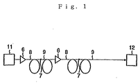
- Fig. 1 is a configuration view showing an optical communication system to which one embodiment of an optical transmission line according to the present invention is applied;
- Fig. 2 is a descriptive diagram showing an example of the refractive index profile of the first optical fiber which is applied to the above described embodiment and an optical transmission line of another embodiment according to the present invention;
- Fig. 3 is a descriptive diagram showing an example of the refractive index profile of the second optical fiber which is applied to the optical transmission line of the above described embodiment;
- Fig. 4 is a graph showing, respectively, examples of dispersion characteristics of the first optical fiber, the second optical fiber and the optical transmission line formed by connecting those optical fibers;
- Fig. 5 is a configuration view showing an optical communication system to which another embodiment of the optical transmission line according to the present invention is applied.
- Fig. 1 shows a system configuration of the optical transmission system comprising one embodiment of the optical transmission line according to the present invention.
- the optical transmission line of the present embodiment is formed by connecting the first optical fiber 8 and the second optical fiber 9 in series.
- a fused connection part between the first optical fiber 8 and the second optical fiber 9 is denoted as 7, an optical transmitter is denoted as 11 and an optical receiver is denoted as 12.
- an optical amplifier 6 is provided to the incoming end of the first optical fiber 8.
- the most characteristic point of the present invention is that an optical transmission line is formed by connecting the first and the second optical fibers 8 and 9 which have the following characteristics in series so that the dispersion value in the set wavelength band within the 1.5 ⁇ m wavelength band for the entire optical transmission line is made approximately zero (-1 ps/nm/km to +1 ps/nm/km).
- the dispersion value in the set wavelength band within the 1.5 ⁇ m wavelength band is 6 to 14 ps/nm/km.
- the dispersion value in the set wavelength band within the 1.5 ⁇ m wavelength band is -14 to -6 ps/nm/km.
- the dispersion slope of the first optical fiber 8 is positive
- the dispersion slope of the second optical fiber 9 is negative
- the dispersion slopes of the first optical fiber 8 and the second optical fiber 9 are, mutually, of opposite symbols.
- the dispersion slope in the set wavelength band within the 1.5 ⁇ m wavelength band for the entire optical transmission line is made approximately zero.
- the signal light wavelength transmitted from the optical transmitter 11 is the wavelength of the set wavelength band within the 1.5 ⁇ m wavelength band and light, with a plurality of mutually different wavelengths in this wavelength band, is transmitted along the optical transmission line while being amplified by the optical amplifier 6.
- the optical amplifier 6 is an erbium dope light fiber type optical amplifier which effectively amplifies light of the set wavelength band within the 1.5 ⁇ m wavelength band.
- a positive dispersion optical fiber where the dispersion in the set wavelength band within the 1.5 ⁇ m wavelength band is a positive dispersion and a negative dispersion optical fiber where the dispersion in the same wavelength band is a negative dispersion are compared to find that the positive dispersion optical fiber comes to have less non-linearity than the negative dispersion optical fiber when light of the same wavelength band enters.
- the first optical fiber 8 is found to be the positive dispersion optical fiber from the dispersion characteristics in the set wavelength band within the 1.5 ⁇ m wavelength band and the second optical fiber 9 is the negative dispersion optical fiber. Therefore, as for the characteristics when light of the set wavelength band within the 1.5 ⁇ m wavelength band enters, the first optical fiber 8 comes to have less non-linearity than the second optical fiber 9.
- the first optical fiber 8 is connected to the emission end of the optical amplifier 6. That is to say, the optical transmission line of the present embodiment arranges the first optical fiber 8 and the second optical fiber 9 so that the closer to the side where the intense light signal is inputted the less non-linearity the optical fiber comes to have.
- the transmission loss in the wavelength of 1.55 ⁇ m is 0.25 dB/km or less and the polarized wave mode dispersion value in the wavelength of 1.55 ⁇ m is 0.15 ps/km 1/2 or less.
- the optical transmission line of the present embodiment is made so that the bending loss with the bending diameter of 20 mm in the wavelength of 1.55 ⁇ m is 10 dB/m or less and the mode field diameter in the wavelength of 1.55 ⁇ m is 5.5 ⁇ m or more.
- the first optical fiber 8 comprising the optical transmission line of the present embodiment is described in detail.
- the first optical fiber 8 has any one of the refractive index profiles as shown in Figs. 2 (a) to 2(c).
- An optical fiber of the refractive index profile as shown in Fig. 2(a) is a depressed center core type optical fiber. This optical fiber is formed by covering the center core 1 with the side core 2, of which the refractive index is larger than that of the center core 1, and by covering the side core 2 with the cladding 5, of which the refractive index is smaller than that of the side core 2 and larger than that of the center core 1.
- Optical fibers of the refractive index profiles as shown in Figs. 2(b) and 2(c) have the following refractive index profiles. That is to say, those optical fibers are formed by covering the center core 1 with the first side core 3, by covering the first side core 3 with the second side core 4 and by covering the second side core 4 with the cladding 5. Then, those optical fibers satisfy ⁇ 2> ⁇ 3> ⁇ 1 when the relative refractive index difference of the center core 1 for the cladding 5 is ⁇ 1, the relative refractive index difference of the first side core 3 for the cladding 5 is ⁇ 2 and the relative refractive index difference of the second side core 4 for the cladding 5 is ⁇ 3.
- the present inventors first assumed that the refractive index profile of the first optical fiber 8 is the refractive index profile as shown in Fig. 2 (a).
- the relative refractive index difference ⁇ 1 of the center core 1 for the cladding 5 and the relative refractive index difference ⁇ 2 of the side core 2 for the cladding 5 are varied in core diameter in various ways.
- the above described relative refractive index differences ⁇ 1 and ⁇ 2 the value (a/b) of the diameter a of the center core 1 divided by the diameter b of the side core 2 (Ra), and a value of core diameter (the diameter of the side core 2) are found so that the dispersion value in the wavelength 1.55 ⁇ m, the dispersion slope, the effective core section area (A eff ) and the bending loss have suitable values and the cut off wavelength ( ⁇ c) has also a suitable value.
- the above described values are found through the use of a simulation, of which the results are shown in Table 1. ⁇ 1 ⁇ 2 Ra Core diam.
- Each of the relative refractive index differences ⁇ 1 and ⁇ 2 are defined by the following equations (3) and (4) when the refractive index of the vacuum is 1, the relative refractive index of the center core is n1, the relative refractive index of the side core 2 is n2 and the relative refractive index of the cladding 5 is nc, of which the unit is %.
- ⁇ 1 [ ⁇ (n1) 2 -(nc) 2 ⁇ /2(n1) 2 ] ⁇ 100
- ⁇ 2 [ ⁇ (n2) 2 -(nc) 2 ⁇ /2(n2) 2 ) ⁇ 100
- the effective core section area is 80 ⁇ m 2 or more in either optical fiber in Examples 1 and 2. That is to say, it can be confirmed that in the optical fibers of Examples 1 and 2, the effective core section area which is the same or more of the effective core section area of a conventional single mode optical fiber is gained.
- the slope in Table 1 is a dispersion slope in the wavelength of 1.55 ⁇ m, and in the optical fiber of Examples 1 and 2 the absolute value of the dispersion slope in the wavelength 1.55 ⁇ m is very small.
- An optical fiber having the depressed center core type refractive index profile as shown in Fig. 2(a) does not include germanium in the center core 1. Therefore, this type of optical fiber has a small non-linearity refractive index, which makes it possible to control the waveform distortion resulting from the self-phase modulation or the cross-phase modulation, or the like.
- the dispersion value in the set wavelength band within the 1.5 ⁇ m wavelength band is in a range of 6 to 14 ps/nm/km. This value is large enough to be able to control the four light wave mixture within the range where the waveform distortion resulting from a local dispersion can be controlled. Therefore, the optical fibers of Examples 1 and 2 are able to control the waveform distortion resulting from a local dispersion and the waveform distortion resulting from the four light wave mixture.
- the relative refractive index difference ⁇ 1 is defined by the above described equation (3).
- ⁇ 2 and ⁇ 3 are, respectively, defined by the above described equation (4) and the following equation (5) when the refractive index of the vacuum is 1, the refractive index of the first side core 3 is n2 and the refractive index of the second side core 4 is n3.
- the unit of those relative refractive index differences ⁇ 1 to ⁇ 3 is %.
- ⁇ 3 [ ⁇ (n3) 2 -(nc) 2 ⁇ /2(n3) 2 ] ⁇ 100
- the refractive index profiles of Trial Examples 3 and 4 in Table 2 have the refractive index profile as shown in Fig. 2(b).
- the second side core 4 is formed by germanium doped crystal and the refractive index of the second side core 4 is larger than the refractive index of cladding 5.
- the refractive index profiles of Trial Examples 5 and 6 in Table 2 have the refractive index profiles as shown in Fig. 2(c).
- the second side core 4 is formed by fluoride doped crystal and the refractive index of the second side core 4 is smaller than the refractive index of the cladding 5.
- optical fibers of Trial Examples 1 to 6 are found to have excellent characteristics, being almost the same as the simulation result as shown in Table 1. That is to say, optical fibers of those Trial Examples 1 to 6 have the effective core section area of approximately 80 ⁇ m 2 and the control of the waveform distortion is possible by the self-phase modulation, the cross-phase modulation, or the like. And in the optical fibers of Trial Examples 1 to 6 the dispersion value in the set wavelength band within the 1.5 ⁇ m wavelength band is a range of 6 to 14 ps/nm/km.
- This value is in a range wherein the waveform distortion resulting from a local dispersion can be controlled and is large enough to control the four light wave mixture and it is confirmed that the optical fibers of Trial Examples 1 to 6 can control the waveform distortion resulting from a local dispersion as well as the waveform distortion resulting from the four light wave mixture.
- the optical fibers of Examples 1 and 2 can control the transmission loss in the wavelength 1.55 ⁇ m.
- the value of polarized wave mode dispersion is approximately 0.1 ps/km 1/2 , which is a small value.
- the second optical fiber 9 has a refractive index profile as shown in either one of Figs. 3 (a) and 3 (b).
- the optical fiber with the refractive index profile as shown in Fig. 3 (a) is a W-type optical fiber. This optical fiber is formed by covering the center core 1 with the side core 2 of which the refractive index is smaller than that of the center core 1 and by covering the side core 2 with the cladding 5, of which the refractive index is larger than that of the side core 2 and smaller than that of the center core 1.
- the optical fiber with the refractive index profile as shown in Fig. 3 (b) is formed by covering the center core 1 with the first side core 3, by covering the first side core 3 with the second side core 4 and by covering the second side core 4 with the cladding 5. Then, this optical fiber satisfies ⁇ 1> ⁇ 3> ⁇ 2 when the relative refractive index difference of the center core 1 to the cladding 5 is ⁇ 1, the relative refractive index difference of the first side core 3 to the cladding 5 is ⁇ 2 and the relative refractive index difference of the second side core 4 to the cladding 5 is ⁇ 3.
- the refractive index profile of the second optical fiber 9 is the refractive index profile as shown in Fig. 3(a).
- the relative refractive index difference ⁇ 2 of the side core 2 to the cladding 5 and the diameter of the core are varied in many ways.
- the values of the relative refractive index differences ⁇ 1, ⁇ 2, Ra and the core diameter are found so that the dispersion value in the wavelength of 1.55 ⁇ m, the dispersion slope, the effective core section area (A eff ) and bending loss have suitable values and the cut off wavelength has also a suitable value. These values are found by use of a simulation, of which the result is shown in Table 3. ⁇ 1 ⁇ 2 Ra Core diam.
- each of the relative refractive index differences ⁇ 1 and ⁇ 2 is found in the same way as each of the relative refractive index differences ⁇ 1 and ⁇ 2 in Table 1.
- either optical fiber of Examples 3 and 4 has the dispersion value in the set wavelength band within the 1.5 ⁇ m wavelength band which is within the range of -14 to -6 ps/nm/km. That is to say, it is confirmed that in the optical fibers of Examples 3 and 4, the absolute value of the dispersion value in the above described set wavelength band is large enough to be able to control the four light wave mixture within the range where a local dispersion can be controlled and control the waveform distortion due to the four light wave mixture.
- the first optical fiber 8 has the dispersion value in the set wavelength band within the 1.5 ⁇ m wavelength band which is within the range of 6 to 14 ps/nm/km. Therefore, by connecting this second optical fiber 9 to this first optical fiber 8, the dispersions in the set wavelength band within the 1.5 ⁇ m wavelength band of the first optical fiber 8 and the second optical fiber are offset. Accordingly, the optical transmission line according to the present embodiment which is formed by connecting the first optical fiber 8 and the second optical fiber 9 in series is considered to be able to implement a low dispersion over a broad wavelength range.
- the relative refractive index difference ⁇ 1 is defined by the above described equation (3).
- ⁇ 2 and ⁇ 3 in the optical fibers of Trial Examples 9 and 10 are defined by the above described equations (4) and (5) when the refractive index of the first side core 3 is n2 and the refractive index of the second side core 4 is n3 while the refractive index of the vacuum is 1.
- the unit of those relative refractive index differences ⁇ 1 to ⁇ 3 is %.
- the second side core 4 is formed of germanium doped crystal.
- the optical fibers of Trial Examples 7 to 10 have excellent characteristics in the same. way as the simulation result shown in Table 3. That is to say, the optical fibers of Trial Examples 7 to 10 have the dispersion value in the set wavelength band within the 1.5 ⁇ m wavelength band which is within the range of -14 to -6 ps/nm/km. This value is within the range where the absolute value of the dispersion value of the above described set wavelength can control the waveform distortion due to a local dispersion and is a value large enough to be able to control the four light wave mixture. Therefore, it is confirmed that the optical fibers of Trial Examples 7 to 10 are able to control both the waveform distortion due to a local dispersion and the waveform distortion due to the four light wave mixture.
- an optical transmission line formed by connecting the first optical fiber 8 and the second optical fiber 9 in series can implement a low dispersion over a broad wavelength range.
- optical fibers of Examples 3 and 4 are also able to control the transmission loss in the wavelength 1.55 ⁇ m.
- all those optical fibers have a polarized wave mode dispersion value of approximately 0.1 ps/km 1/2 , which is a low value.
- the present inventors trial manufactured the first and the second optical fibers 8 and 9, respectively, as described above and, afterwards, trial manufactured an optical transmission line by connecting the first optical fiber 8 and the second optical fiber 9 in series by fusion connection. Then, the fusion connection loss of this optical transmission line was measured and it was found that the average connection loss was approximately 0.6 dB. And a dispersion shift optical fiber, of which the mode field diameter in the wavelength of 1.55 ⁇ m is approximately 8 ⁇ m, is provided between the first optical fiber 8 and the second optical fiber 9 and the connection loss at this time was measured and found to be approximately 0.5 dB.
- the characteristic curve a in Fig. 4 shows a dispersion characteristic example in the set wavelength band within the 1.5 ⁇ m wavelength band of the first optical fiber 8 and the characteristic curve b in Fig. 4 shows a dispersion characteristic example in the set wavelength band within the 1.5 ⁇ m wavelength band of the second optical fiber 9, respectively.
- the characteristic curve c in Fig. 4 shows a dispersion characteristic example when the first optical fiber 8 and the second optical fiber are connected by providing 2km of the above described dispersion shift optical fiber between 20km of the first optical fiber 8 and 20km of the second optical fiber 9.
- the dispersions in the set wavelength band within the 1.5 ⁇ m wavelength band of the first optical fiber 8 and the second optical fiber 9 are offset. Accordingly, an optical transmission line formed by connecting the first optical fiber 8 and the second optical fiber 9 in series has been confirmed to implement a low dispersion over broad wavelength range.
- the refractive index profiles of the first optical fiber 8 and the second optical fiber 9 are, respectively, determined based on the above examined result. Then, based on those refractive index profiles, the dispersion value in the set wavelength band within the 1.5 ⁇ m wavelength band of the first optical fiber is set between 6 to 14 ps/nm/km while the dispersion value in the set wavelength band within the 1.5 ⁇ m wavelength band of the second optical fiber 9 is set between -14 to -6 ps/nm/km.
- an optical transmission line is formed by connecting those optical fibers in series. Accordingly, in the present embodiment, the dispersion value (total dispersion value) in the set wavelength band within the 1.5 ⁇ m wavelength band is made approximately zero while in the entire optical transmission line the residual dispersion is make approximately zero so as to be able to control the distortion of the signal waveform due to the residual dispersion.
- the above described first and second optical fibers 8 and 9 both have the absolute value of the dispersion value in the set wavelength band within the 1.5 ⁇ m wavelength band of 6 ps/nm/km or more. That is to say, in the first and second optical fibers 8 and 9, the dispersion value in the wavelength 1.55 ⁇ m is shifted from zero and, therefore; the occurrence of the four light wave mixture which is supposed to dramatically influence the waveform distortion due to the non-linearity phenomenon becomes controllable and the waveform distortion due to non-linearity phenomenon can be controlled.
- said first and second optical fibers both have the absolute value of the dispersion value in the set wavelength band within the 1.5 ⁇ m wavelength band of 14 ps/nm/km or less and the absolute value of the dispersion value in the set wavelength band within the 1.5 ⁇ m wavelength band is smaller compared to that of a single mode optical fiber, or the like. Therefore, in the optical transmission line of the present embodiment, a local dispersion in each optical fiber forming the optical transmission line can be controlled and the waveform distortion due to the dispersion becomes controllable.
- the first optical fiber 8 and the second optical fiber 9 are arranged so that the closer to the end to which the strong optical signal is inputted, the lower the non-linearity of the optical fiber is (the first optical fiber 8 is connected to the emission end of the optical amplifier 6 and the second optical fiber 9 is connected to the emission end of the first optical fiber 8). Therefore, in an optical transmission line according to the present embodiment, the control of waveform distortion due to the non-linearity phenomenon can be carried out without failure.
- the mode field diameter in the wavelength 1.55 ⁇ m of the first optical fiber 8 is made 9.5 ⁇ m or more so that the effective core section area becomes as large as approximately 80 ⁇ m 2 .
- the mode field diameter in the wavelength 1.55 ⁇ m of the second optical fiber 9 is made 5.5 ⁇ m or more, which becomes larger than that of a conventional negative dispersion optical fiber. Therefore, in an optical transmission line according to the present embodiment, the influence caused by the self-phase modulation, the cross-phase modulation, or the like, within the non-linearity phenomenon can be controlled so as to carry out the control of the waveform distortion due to the non-linearity phenomenon without failure.
- the transmission loss in the 1.55 ⁇ m wavelength of the first optical fiber 8 is 0.25 dB/km or less
- the polarized wave mode dispersion value in the wavelength 1.55 ⁇ m is 0.15 ps/km 1/2 or less
- the bending loss with the bending diameter of 20 mm in the wavelength 1.55 ⁇ m is 10 dB/m or less
- the transmission loss in the wavelength 1.55 ⁇ m of the second optical fiber 9 is 0.30 dB/km or less
- the polarized wave mode dispersion value in the wavelength 1.55 ⁇ m is 0.15 ps/km 1/2 or less
- the bending loss with the bending diameter 20 mm in the wavelength 1.55 ⁇ m is 10 dB/m or less.
- the transmission loss in the set wavelength band within the 1.5 ⁇ m wavelength band is small, the waveform distortion due to a polarized wave mode dispersion can be controlled and the loss due to bending can be made smaller so that the signal light transmission can be performed under excellent conditions.
- the first optical fiber 8 may be formed by covering the core 10 with the cladding 5, as shown in Fig. 2 (d), to become a single peak-type optical fiber of which the refractive index distribution forms a profile of the ⁇ th power.
- the first optical fiber 8 may be a step type optical fiber which is formed by covering the center core 1 with the side core 2 of which the refractive index is smaller than that of the center core 1 and by covering the side core 2 with the cladding 5 of which the refractive index is smaller than that of the side core 2 as shown in Fig. 2(e).
- the center core 1 has a refractive index distribution forming a profile of the ⁇ th power.
- Table 5 shows the characteristics of Examples 5 and 6 of the above described single peak-type optical fiber and Table 6 shows the characteristics of Examples 7 and 8 of the above described step type optical fiber.
- ⁇ which shows the refractive distribution form of the core 10 and the center core 1
- ⁇ 1 ⁇ Core diam is also shown.
- Example 5 0.40 3.0 10.5 13.1 0.062 77.4 1859 7.0
- Example 6 0.45 2.0 9.4 13.4 0.061 72.5 1166 9.5 ⁇ 1 ⁇ ⁇ 2 Ra Core diam.
- the relative refractive index difference ⁇ 1 is defined as in the above described equation (3) when the relative refractive index of the core 10 is nl and the relative refractive index of the cladding 5 is nc while the refractive index of the vacuum is 1, of which the unit is %.
- each of the relative refractive index differences ⁇ 1 and ⁇ 2 is defined as in the above described equations (3) and (4) when the relative refractive index of the center core is n1, the relative refractive index of the side core 2 is n2 and the relative refractive index of the cladding 5 is nc while the refractive index of the vacuum is 1, of which the unit is %.
- the same effects as in the above described embodiments can be gained by properly setting the detailed values of the refractive index profile (the relative refractive index differences ⁇ 1 and ⁇ 2, ⁇ , or the like).
- each of the values of the relative refractive index differences ⁇ 1, ⁇ 2 and ⁇ 3 in the refractive index profiles of the first and second optical fibers 8 and 9 is not limited to that of each of the above described examples and trial examples. That is to say, each value of the relative refractive index differences ⁇ 1, ⁇ 2 and ⁇ 3 may be properly set so as to have the dispersion characteristic such as for the first optical fiber 8 and the second optical fiber 9 in the above described embodiments.
- Each value of the relative refractive index differences ⁇ 1, ⁇ 2 and ⁇ 3 is, preferably, set taking the transmission loss in the set wavelength band within the 1.5 ⁇ m wavelength band, a polarized wave mode dispersion, and a bending loss, or the like, into account.
- the number and the arrangement order of the first optical fibers 8 and the second optical fibers 9 forming the optical transmission line of the present invention are not specifically limited but they should be properly adjusted.
- the optical transmission line is formed by connecting the first optical fibers 8 and the second optical fibers 9 without providing optical amplifiers, it is possible to lower the possibility of the occurrence of the non-linearity phenomenon by arranging the optical fibers so that the closer to the input end of the optical signal optical fibers are, the lower the non-linearity of the optical fibers is.
- the second optical fiber 9 is connected between the two first optical fibers 8 so that an optical transmission line can be formed wherein bi-directional communication for transmitting and receiving light becomes possible by using the optical transceiver 13.
- an optical transmission line according to the present invention, a local dispersion in the first and the second optical fibers can be controlled, the waveform distortion due to a local dispersion can be controlled and the dispersion value (total dispersion value) in the set wavelength band within the 1.5 ⁇ m wavelength band for the entire optical transmission line is made approximately zero. Therefore, the optical transmission line of the present invention has little residual dispersion over the entire optical transmission line and can control the distortion of the signal waveform due to the residual dispersion, and is suitable as an optical transmission line for wavelength division multiplexed transmission of the 1.5 ⁇ m wavelength band or the like.
Landscapes
- Physics & Mathematics (AREA)
- Chemical & Material Sciences (AREA)
- Dispersion Chemistry (AREA)
- General Physics & Mathematics (AREA)
- Optics & Photonics (AREA)
- Electromagnetism (AREA)
- Engineering & Computer Science (AREA)
- Computer Networks & Wireless Communication (AREA)
- Signal Processing (AREA)
- Optical Communication System (AREA)
Applications Claiming Priority (3)
| Application Number | Priority Date | Filing Date | Title |
|---|---|---|---|
| JP18145399 | 1999-06-28 | ||
| JP18145399 | 1999-06-28 | ||
| PCT/JP2000/004206 WO2001001179A1 (en) | 1999-06-28 | 2000-06-27 | Optical transmission line |
Publications (1)
| Publication Number | Publication Date |
|---|---|
| EP1116970A1 true EP1116970A1 (de) | 2001-07-18 |
Family
ID=16101036
Family Applications (1)
| Application Number | Title | Priority Date | Filing Date |
|---|---|---|---|
| EP00940849A Withdrawn EP1116970A1 (de) | 1999-06-28 | 2000-06-27 | Optische übertragungsstrecke |
Country Status (5)
| Country | Link |
|---|---|
| US (2) | US6724966B2 (de) |
| EP (1) | EP1116970A1 (de) |
| JP (1) | JP4494691B2 (de) |
| CA (1) | CA2340947A1 (de) |
| WO (1) | WO2001001179A1 (de) |
Cited By (7)
| Publication number | Priority date | Publication date | Assignee | Title |
|---|---|---|---|---|
| FR2828937A1 (fr) * | 2001-08-23 | 2003-02-28 | Cit Alcatel | Fibre optique pour systeme de transmission a multiplexage en longueurs d'ondes |
| EP1267504A3 (de) * | 2001-06-12 | 2003-07-23 | The Furukawa Electric Co., Ltd. | Optische Übertragungsverbindung |
| EP1233288A3 (de) * | 2001-02-16 | 2004-05-26 | The Furukawa Electric Co., Ltd. | Optische Faser und optische Übertragungsleitung |
| EP1241810A3 (de) * | 2001-03-15 | 2005-04-06 | Fujikura Ltd. | Wellenlängenmultiplexierter Übertragungsweg und dafür verwendete dispersionskompensierende Faser |
| WO2006010798A1 (en) * | 2004-07-26 | 2006-02-02 | Photonium Oy | Multimode optical fiber with low differential mode delay |
| EP1628149A1 (de) * | 2004-08-11 | 2006-02-22 | The Furukawa Electric Co., Ltd. | Optische Faser, optisches Faserbändchen und optisches Verbindungssystem |
| EP2562571A3 (de) * | 2011-08-25 | 2015-05-27 | Sumitomo Electric Industries, Ltd. | Glasfaser |
Families Citing this family (51)
| Publication number | Priority date | Publication date | Assignee | Title |
|---|---|---|---|---|
| US6421490B1 (en) | 1998-02-23 | 2002-07-16 | Corning Incorporated | Low slope dispersion managed waveguide |
| FR2816065B1 (fr) * | 2000-10-26 | 2003-01-17 | Cit Alcatel | Fibre optique pour la compensation en ligne de la dispersion chromatique d'une fibre optique a dispersion chromatique positive |
| US6611647B2 (en) | 2000-12-12 | 2003-08-26 | Corning Incorporated | Large effective area optical fiber |
| US6943935B2 (en) * | 2001-03-16 | 2005-09-13 | Corning Incorporated | Dispersion-managed cable for raman-assisted transmission |
| CA2380342A1 (en) * | 2001-04-13 | 2002-10-13 | The Furukawa Electric Co., Ltd | Dispersion management optical transmission system and optical transmission line |
| JP4413456B2 (ja) * | 2001-08-27 | 2010-02-10 | 古河電気工業株式会社 | 負分散光ファイバおよび該負分散光ファイバを用いた光伝送路 |
| FR2828939B1 (fr) * | 2001-08-27 | 2004-01-16 | Cit Alcatel | Fibre optique pour un systeme de transmission a multiplexage en longueurs d'onde |
| JP2003066262A (ja) * | 2001-08-29 | 2003-03-05 | Sumitomo Electric Ind Ltd | 光伝送路および光通信システム |
| JP2003188822A (ja) * | 2001-10-10 | 2003-07-04 | Furukawa Electric Co Ltd:The | 光伝送路およびその光伝送路を用いた光伝送システム |
| JP2003241000A (ja) | 2002-02-19 | 2003-08-27 | Furukawa Electric Co Ltd:The | 光ファイバおよびその光ファイバを用いた光増幅器ならびに光伝送システム |
| US20040028319A1 (en) * | 2002-07-03 | 2004-02-12 | Mahesh Ajgaonkar | Optical communication system and method |
| CN100510811C (zh) * | 2002-07-31 | 2009-07-08 | 康宁股份有限公司 | 具有大有效面积、低斜率以及低零色散的非零色散位移光纤 |
| FR2845486B1 (fr) | 2002-10-07 | 2005-01-28 | Cit Alcatel | Fibre optique a compensation de dispersion chromatique |
| US7103251B2 (en) * | 2002-12-31 | 2006-09-05 | Corning Incorporated | Dispersion flattened NZDSF fiber |
| NL1024015C2 (nl) | 2003-07-28 | 2005-02-01 | Draka Fibre Technology Bv | Multimode optische vezel voorzien van een brekingsindexprofiel, optisch communicatiesysteem onder toepassing daarvan en werkwijze ter vervaardiging van een dergelijke vezel. |
| JP4461966B2 (ja) * | 2003-09-05 | 2010-05-12 | 住友電気工業株式会社 | 光増幅用ファイバ、光増幅モジュール、光通信システム及び光増幅方法 |
| US6985662B2 (en) * | 2003-10-30 | 2006-01-10 | Corning Incorporated | Dispersion compensating fiber for moderate dispersion NZDSF and transmission system utilizing same |
| JP5279980B2 (ja) * | 2004-01-08 | 2013-09-04 | 日本電信電話株式会社 | 単一モード光ファイバ |
| CN100397117C (zh) * | 2004-01-26 | 2008-06-25 | 古河电气工业株式会社 | 非线性色散偏移光纤 |
| US7187833B2 (en) * | 2004-04-29 | 2007-03-06 | Corning Incorporated | Low attenuation large effective area optical fiber |
| JP4699751B2 (ja) * | 2004-12-27 | 2011-06-15 | 株式会社日立製作所 | 分散補償装置 |
| KR100759805B1 (ko) * | 2005-12-07 | 2007-09-20 | 한국전자통신연구원 | 광증폭 듀플렉서 |
| FR2922657B1 (fr) | 2007-10-23 | 2010-02-12 | Draka Comteq France | Fibre multimode. |
| US7978949B2 (en) * | 2007-11-13 | 2011-07-12 | The Furukawa Electric Co., Ltd. | Optical fibers and optical transmission systems |
| JP2009122277A (ja) * | 2007-11-13 | 2009-06-04 | Furukawa Electric Co Ltd:The | 光ファイバおよび光伝送システム |
| FR2932932B1 (fr) * | 2008-06-23 | 2010-08-13 | Draka Comteq France Sa | Systeme optique multiplexe en longueur d'ondes avec fibres optiques multimodes |
| FR2933779B1 (fr) * | 2008-07-08 | 2010-08-27 | Draka Comteq France | Fibres optiques multimodes |
| FR2940839B1 (fr) * | 2009-01-08 | 2012-09-14 | Draka Comteq France | Fibre optique multimodale a gradient d'indice, procedes de caracterisation et de fabrication d'une telle fibre |
| FR2946436B1 (fr) | 2009-06-05 | 2011-12-09 | Draka Comteq France | Fibre optique multimode a tres large bande passante avec une interface coeur-gaine optimisee |
| FR2957153B1 (fr) * | 2010-03-02 | 2012-08-10 | Draka Comteq France | Fibre optique multimode a large bande passante et a faibles pertes par courbure |
| FR2953605B1 (fr) * | 2009-12-03 | 2011-12-16 | Draka Comteq France | Fibre optique multimode a large bande passante et a faibles pertes par courbure |
| FR2949870B1 (fr) * | 2009-09-09 | 2011-12-16 | Draka Compteq France | Fibre optique multimode presentant des pertes en courbure ameliorees |
| FR2953606B1 (fr) * | 2009-12-03 | 2012-04-27 | Draka Comteq France | Fibre optique multimode a large bande passante et a faibles pertes par courbure |
| FR2953030B1 (fr) * | 2009-11-25 | 2011-11-18 | Draka Comteq France | Fibre optique multimode a tres large bande passante avec une interface coeur-gaine optimisee |
| US9014525B2 (en) | 2009-09-09 | 2015-04-21 | Draka Comteq, B.V. | Trench-assisted multimode optical fiber |
| FR2953029B1 (fr) | 2009-11-25 | 2011-11-18 | Draka Comteq France | Fibre optique multimode a tres large bande passante avec une interface coeur-gaine optimisee |
| FR2950156B1 (fr) * | 2009-09-17 | 2011-11-18 | Draka Comteq France | Fibre optique multimode |
| JP5619516B2 (ja) | 2010-08-04 | 2014-11-05 | 古河電気工業株式会社 | 光ファイバ |
| FR2966256B1 (fr) | 2010-10-18 | 2012-11-16 | Draka Comteq France | Fibre optique multimode insensible aux pertes par |
| FR2971061B1 (fr) | 2011-01-31 | 2013-02-08 | Draka Comteq France | Fibre optique a large bande passante et a faibles pertes par courbure |
| DK2482106T5 (da) | 2011-01-31 | 2014-09-22 | Draka Comteq Bv | Multimode-fiber |
| EP2503368A1 (de) | 2011-03-24 | 2012-09-26 | Draka Comteq B.V. | Multimodus-Glasfaser mit verbesserter Biegefestigkeit |
| EP2506044A1 (de) | 2011-03-29 | 2012-10-03 | Draka Comteq B.V. | Multimodus-Glasfaser |
| EP2518546B1 (de) | 2011-04-27 | 2018-06-20 | Draka Comteq B.V. | Strahlungsgresistente multimodale optische Faser mit hoher Bandbreite |
| EP2541292B1 (de) | 2011-07-01 | 2014-10-01 | Draka Comteq BV | Multimode-Lichtleitfaser |
| US9366806B2 (en) * | 2012-08-29 | 2016-06-14 | Ofs Fitel, Llc | Gain-producing fibers with increased cladding absorption while maintaining single-mode operation |
| US9366810B2 (en) * | 2012-08-29 | 2016-06-14 | Ofs Fitel, Llc | Double-clad, gain-producing fibers with increased cladding absoroption while maintaining single-mode operation |
| JP5986594B2 (ja) * | 2014-02-14 | 2016-09-06 | 株式会社フジクラ | 光デバイス |
| JP2015172726A (ja) * | 2014-02-20 | 2015-10-01 | 株式会社フジクラ | 光ファイバおよび光ファイバの製造方法 |
| JP5946196B2 (ja) * | 2014-04-01 | 2016-07-05 | 日本電信電話株式会社 | ファイバおよびファイバ増幅器 |
| WO2016108848A1 (en) * | 2014-12-30 | 2016-07-07 | Halliburton Energy Services, Inc. | Correction of chromatic dispersion in remote distributed sensing |
Family Cites Families (26)
| Publication number | Priority date | Publication date | Assignee | Title |
|---|---|---|---|---|
| US4252796A (en) * | 1979-08-17 | 1981-02-24 | Yu Ruey J | Stable water-in-oil emulsions |
| JPH0672967B2 (ja) * | 1985-07-13 | 1994-09-14 | 株式会社フジクラ | 零分散単一モ−ド光フアイバ |
| JPS6252508A (ja) * | 1985-09-02 | 1987-03-07 | Nippon Telegr & Teleph Corp <Ntt> | 光フアイバ |
| JPS62291605A (ja) * | 1986-06-11 | 1987-12-18 | Sumitomo Electric Ind Ltd | 光フアイバ |
| JP2668677B2 (ja) * | 1986-06-18 | 1997-10-27 | 株式会社フジクラ | 分散シフト光フアイバ |
| JPH0318161A (ja) | 1989-06-15 | 1991-01-25 | Toshiba Corp | 電話機 |
| US5191631A (en) * | 1991-12-19 | 1993-03-02 | At&T Bell Laboratories | Hybrid optical fiber and method of increasing the effective area of optical transmission using same |
| JPH09211511A (ja) * | 1996-02-05 | 1997-08-15 | Furukawa Electric Co Ltd:The | 光通信システム |
| CA2195614C (en) * | 1996-02-16 | 2005-06-28 | George F. Wildeman | Symmetric, dispersion-manager fiber optic cable and system |
| JP3760557B2 (ja) * | 1996-04-15 | 2006-03-29 | 住友電気工業株式会社 | 分散補償ファイバ及びそれを含む光伝送システム |
| CA2202586C (en) * | 1996-04-15 | 2003-05-06 | Masashi Onishi | Dispersion compensating fiber and optical transmission system including the same |
| DE69837506T2 (de) * | 1997-02-26 | 2007-12-27 | Nippon Telegraph And Telephone Corp. | Optische Faser |
| JP3450696B2 (ja) * | 1997-02-26 | 2003-09-29 | 日本電信電話株式会社 | 光ファイバ |
| CA2232101A1 (en) * | 1997-03-25 | 1998-09-25 | Kazunori Mukasa | Dispersion compensating optical fiber, and wavelength division multiplex light transmission line using the same |
| US5887105A (en) * | 1997-04-28 | 1999-03-23 | Corning Incorporated | Dispersion managed optical fiber |
| JP3018161B2 (ja) | 1997-06-09 | 2000-03-13 | 広島大学長 | 血液循環補助装置 |
| JPH11167038A (ja) * | 1997-12-05 | 1999-06-22 | Sumitomo Electric Ind Ltd | 分散シフト光ファイバ |
| US6470126B1 (en) * | 1998-10-23 | 2002-10-22 | The Furukawa Electric Co., Ltd. | Dispersion compensating optical fiber, and wavelength division multiplexing transmission line using a dispersion compensating optical fiber |
| EP1146358A4 (de) * | 1998-11-26 | 2005-09-07 | Sumitomo Electric Industries | Optische faser und optisches übertragungssystem mit dieser faser |
| CN1173199C (zh) * | 1999-02-22 | 2004-10-27 | 古河电气工业株式会社 | 光学传输线、用于所述光学传输线的负色散光纤以及使用所述光学传输线的光学传输系统 |
| TW451088B (en) * | 1999-04-16 | 2001-08-21 | Sumitomo Electric Industries | Optical fiber and optical transmission line including the same |
| EP1124145A1 (de) * | 1999-08-20 | 2001-08-16 | The Furukawa Electric Co., Ltd. | Optische faser und eine diese enthaltende optische übertragungsleitung |
| JP4134468B2 (ja) * | 1999-12-13 | 2008-08-20 | 住友電気工業株式会社 | 光ファイバ |
| FR2816065B1 (fr) * | 2000-10-26 | 2003-01-17 | Cit Alcatel | Fibre optique pour la compensation en ligne de la dispersion chromatique d'une fibre optique a dispersion chromatique positive |
| JP4443788B2 (ja) * | 2001-03-30 | 2010-03-31 | 古河電気工業株式会社 | 光ファイバおよびその光ファイバを用いた光通信システム |
| JP3869305B2 (ja) * | 2001-07-26 | 2007-01-17 | 古河電気工業株式会社 | 光伝送路 |
-
2000
- 2000-06-27 EP EP00940849A patent/EP1116970A1/de not_active Withdrawn
- 2000-06-27 CA CA002340947A patent/CA2340947A1/en not_active Abandoned
- 2000-06-27 WO PCT/JP2000/004206 patent/WO2001001179A1/ja not_active Ceased
- 2000-06-27 JP JP2001507130A patent/JP4494691B2/ja not_active Expired - Fee Related
-
2001
- 2001-02-28 US US09/794,619 patent/US6724966B2/en not_active Expired - Lifetime
-
2004
- 2004-02-20 US US10/781,719 patent/US6810186B2/en not_active Expired - Lifetime
Non-Patent Citations (1)
| Title |
|---|
| See references of WO0101179A1 * |
Cited By (10)
| Publication number | Priority date | Publication date | Assignee | Title |
|---|---|---|---|---|
| EP1233288A3 (de) * | 2001-02-16 | 2004-05-26 | The Furukawa Electric Co., Ltd. | Optische Faser und optische Übertragungsleitung |
| EP1241810A3 (de) * | 2001-03-15 | 2005-04-06 | Fujikura Ltd. | Wellenlängenmultiplexierter Übertragungsweg und dafür verwendete dispersionskompensierende Faser |
| US7031581B2 (en) * | 2001-03-15 | 2006-04-18 | Fujikura Ltd. | Wavelength division multiplexed transmission path and dispersion-compensating fiber used therein |
| EP1267504A3 (de) * | 2001-06-12 | 2003-07-23 | The Furukawa Electric Co., Ltd. | Optische Übertragungsverbindung |
| FR2828937A1 (fr) * | 2001-08-23 | 2003-02-28 | Cit Alcatel | Fibre optique pour systeme de transmission a multiplexage en longueurs d'ondes |
| EP1288682A1 (de) * | 2001-08-23 | 2003-03-05 | Alcatel | Optische Faser für Wellenlängenmultiplex-Übertragungssystem |
| WO2006010798A1 (en) * | 2004-07-26 | 2006-02-02 | Photonium Oy | Multimode optical fiber with low differential mode delay |
| US7646955B2 (en) | 2004-07-26 | 2010-01-12 | Corning Incorporated | Multimode optical fiber with low differential mode delay |
| EP1628149A1 (de) * | 2004-08-11 | 2006-02-22 | The Furukawa Electric Co., Ltd. | Optische Faser, optisches Faserbändchen und optisches Verbindungssystem |
| EP2562571A3 (de) * | 2011-08-25 | 2015-05-27 | Sumitomo Electric Industries, Ltd. | Glasfaser |
Also Published As
| Publication number | Publication date |
|---|---|
| US20020012509A1 (en) | 2002-01-31 |
| US6724966B2 (en) | 2004-04-20 |
| WO2001001179A1 (en) | 2001-01-04 |
| US20040165849A1 (en) | 2004-08-26 |
| CA2340947A1 (en) | 2001-01-04 |
| JP4494691B2 (ja) | 2010-06-30 |
| US6810186B2 (en) | 2004-10-26 |
Similar Documents
| Publication | Publication Date | Title |
|---|---|---|
| US6724966B2 (en) | Optical transmission line | |
| US6084993A (en) | Optical transmission link for division multiplex transmission, and optical fiber constituting the link | |
| US6169837B1 (en) | Dispersion-flattened optical fiber | |
| US6470126B1 (en) | Dispersion compensating optical fiber, and wavelength division multiplexing transmission line using a dispersion compensating optical fiber | |
| US6591048B2 (en) | Dispersion compensating optical fiber and optical transmission line using the optical fiber | |
| EP1083446A1 (de) | Optische übertragungsleitung, optische faser mit negativer dispersion für die optische übertragungsleitung und ein eine optische übertragungsleitung enthaltendes optisches übertragungssystem | |
| EP1146358A1 (de) | Optische faser und optisches übertragungssystem mit dieser faser | |
| JP2002533744A (ja) | 大都市ネットワークシステムおよびアクセスネットワークシステム用の光ファイバ | |
| US6684018B2 (en) | Low-dispersion optical fiber and optical transmission system using the low-dispersion optical fiber | |
| JPWO2001001179A1 (ja) | 光伝送路 | |
| EP1271193A1 (de) | Optische übertragungsleitung und optisches übertragungssystem damit | |
| EP1396743B1 (de) | Dispersionskompensierende optische Faser | |
| CA2267252A1 (en) | Dispersion-shift fiber | |
| CA2388557A1 (en) | Optical fiber for wavelength division multiplexing optical transmission system using densely spaced optical channels | |
| EP1233288A2 (de) | Optische Faser und optische Übertragungsleitung | |
| US7164829B2 (en) | Optical fiber, optical transmission line and optical communications system | |
| US6856738B2 (en) | Optical fiber and optical transmission system | |
| JP3653719B2 (ja) | 光ファイバ伝送路 | |
| JP2002148464A (ja) | 光ファイバ | |
| CA2405146A1 (en) | Dispersion-compensating optical fiber with w-shaped index profile | |
| EP1298821B1 (de) | Optisches Übertragungssystem mit dispersionskompensierenden Fasern | |
| EP0989420A1 (de) | Optischer wellenlängenmultiplexübertragungkanal und hierfür verwendete optische faser | |
| US7289710B2 (en) | Optical fiber suitable for high-speed large-scale wdm system, optical transmission line and optical transmission system using the same | |
| EP1291688A2 (de) | Optische Übertragungsleitung und optisches Übertragungssystem | |
| US6813425B1 (en) | Fiber optic cable for increased transmission capacity and wavelength division multiplexing optical transmission system using the same |
Legal Events
| Date | Code | Title | Description |
|---|---|---|---|
| PUAI | Public reference made under article 153(3) epc to a published international application that has entered the european phase |
Free format text: ORIGINAL CODE: 0009012 |
|
| 17P | Request for examination filed |
Effective date: 20010122 |
|
| AK | Designated contracting states |
Kind code of ref document: A1 Designated state(s): DE FR GB IT |
|
| AX | Request for extension of the european patent |
Free format text: AL;LT;LV;MK;RO;SI |
|
| STAA | Information on the status of an ep patent application or granted ep patent |
Free format text: STATUS: THE APPLICATION HAS BEEN WITHDRAWN |
|
| 18W | Application withdrawn |
Effective date: 20050331 |