EP1120880A2 - Power supply circuit - Google Patents
Power supply circuit Download PDFInfo
- Publication number
- EP1120880A2 EP1120880A2 EP01100460A EP01100460A EP1120880A2 EP 1120880 A2 EP1120880 A2 EP 1120880A2 EP 01100460 A EP01100460 A EP 01100460A EP 01100460 A EP01100460 A EP 01100460A EP 1120880 A2 EP1120880 A2 EP 1120880A2
- Authority
- EP
- European Patent Office
- Prior art keywords
- load
- converter
- converting means
- power supply
- supply circuit
- Prior art date
- Legal status (The legal status is an assumption and is not a legal conclusion. Google has not performed a legal analysis and makes no representation as to the accuracy of the status listed.)
- Withdrawn
Links
Images


Classifications
-
- H—ELECTRICITY
- H02—GENERATION; CONVERSION OR DISTRIBUTION OF ELECTRIC POWER
- H02J—ELECTRIC POWER NETWORKS; CIRCUIT ARRANGEMENTS OR SYSTEMS FOR SUPPLYING OR DISTRIBUTING ELECTRIC POWER; SYSTEMS FOR STORING ELECTRIC ENERGY
- H02J7/00—Circuit arrangements for charging or discharging batteries or for supplying loads from batteries
-
- H—ELECTRICITY
- H02—GENERATION; CONVERSION OR DISTRIBUTION OF ELECTRIC POWER
- H02J—ELECTRIC POWER NETWORKS; CIRCUIT ARRANGEMENTS OR SYSTEMS FOR SUPPLYING OR DISTRIBUTING ELECTRIC POWER; SYSTEMS FOR STORING ELECTRIC ENERGY
- H02J9/00—Circuit arrangements for emergency or stand-by power supply, e.g. for emergency lighting
- H02J9/005—Circuit arrangements for emergency or stand-by power supply, e.g. for emergency lighting using a power saving mode
-
- B—PERFORMING OPERATIONS; TRANSPORTING
- B60—VEHICLES IN GENERAL
- B60L—PROPULSION OF ELECTRICALLY-PROPELLED VEHICLES; SUPPLYING ELECTRIC POWER FOR AUXILIARY EQUIPMENT OF ELECTRICALLY-PROPELLED VEHICLES; ELECTRODYNAMIC BRAKE SYSTEMS FOR VEHICLES IN GENERAL; MAGNETIC SUSPENSION OR LEVITATION FOR VEHICLES; MONITORING OPERATING VARIABLES OF ELECTRICALLY-PROPELLED VEHICLES; ELECTRIC SAFETY DEVICES FOR ELECTRICALLY-PROPELLED VEHICLES
- B60L1/00—Supplying electric power to auxiliary equipment of vehicles
-
- B—PERFORMING OPERATIONS; TRANSPORTING
- B60—VEHICLES IN GENERAL
- B60L—PROPULSION OF ELECTRICALLY-PROPELLED VEHICLES; SUPPLYING ELECTRIC POWER FOR AUXILIARY EQUIPMENT OF ELECTRICALLY-PROPELLED VEHICLES; ELECTRODYNAMIC BRAKE SYSTEMS FOR VEHICLES IN GENERAL; MAGNETIC SUSPENSION OR LEVITATION FOR VEHICLES; MONITORING OPERATING VARIABLES OF ELECTRICALLY-PROPELLED VEHICLES; ELECTRIC SAFETY DEVICES FOR ELECTRICALLY-PROPELLED VEHICLES
- B60L58/00—Methods or circuit arrangements for monitoring or controlling batteries or fuel cells, specially adapted for electric vehicles
- B60L58/10—Methods or circuit arrangements for monitoring or controlling batteries or fuel cells, specially adapted for electric vehicles for monitoring or controlling batteries
- B60L58/18—Methods or circuit arrangements for monitoring or controlling batteries or fuel cells, specially adapted for electric vehicles for monitoring or controlling batteries of two or more battery modules
- B60L58/20—Methods or circuit arrangements for monitoring or controlling batteries or fuel cells, specially adapted for electric vehicles for monitoring or controlling batteries of two or more battery modules having different nominal voltages
-
- H—ELECTRICITY
- H02—GENERATION; CONVERSION OR DISTRIBUTION OF ELECTRIC POWER
- H02J—ELECTRIC POWER NETWORKS; CIRCUIT ARRANGEMENTS OR SYSTEMS FOR SUPPLYING OR DISTRIBUTING ELECTRIC POWER; SYSTEMS FOR STORING ELECTRIC ENERGY
- H02J7/00—Circuit arrangements for charging or discharging batteries or for supplying loads from batteries
- H02J7/14—Circuit arrangements for charging or discharging batteries or for supplying loads from batteries for charging batteries from dynamo-electric generators driven at varying speed, e.g. on vehicle
- H02J7/1415—Circuit arrangements for charging or discharging batteries or for supplying loads from batteries for charging batteries from dynamo-electric generators driven at varying speed, e.g. on vehicle with a generator driven by a prime mover other than the motor of a vehicle
-
- B—PERFORMING OPERATIONS; TRANSPORTING
- B60—VEHICLES IN GENERAL
- B60L—PROPULSION OF ELECTRICALLY-PROPELLED VEHICLES; SUPPLYING ELECTRIC POWER FOR AUXILIARY EQUIPMENT OF ELECTRICALLY-PROPELLED VEHICLES; ELECTRODYNAMIC BRAKE SYSTEMS FOR VEHICLES IN GENERAL; MAGNETIC SUSPENSION OR LEVITATION FOR VEHICLES; MONITORING OPERATING VARIABLES OF ELECTRICALLY-PROPELLED VEHICLES; ELECTRIC SAFETY DEVICES FOR ELECTRICALLY-PROPELLED VEHICLES
- B60L2210/00—Converter types
- B60L2210/10—DC to DC converters
-
- H—ELECTRICITY
- H02—GENERATION; CONVERSION OR DISTRIBUTION OF ELECTRIC POWER
- H02J—ELECTRIC POWER NETWORKS; CIRCUIT ARRANGEMENTS OR SYSTEMS FOR SUPPLYING OR DISTRIBUTING ELECTRIC POWER; SYSTEMS FOR STORING ELECTRIC ENERGY
- H02J2207/00—Details of circuit arrangements for charging or discharging batteries or supplying loads from batteries
- H02J2207/20—Charging or discharging characterised by the power electronics converter
-
- Y—GENERAL TAGGING OF NEW TECHNOLOGICAL DEVELOPMENTS; GENERAL TAGGING OF CROSS-SECTIONAL TECHNOLOGIES SPANNING OVER SEVERAL SECTIONS OF THE IPC; TECHNICAL SUBJECTS COVERED BY FORMER USPC CROSS-REFERENCE ART COLLECTIONS [XRACs] AND DIGESTS
- Y02—TECHNOLOGIES OR APPLICATIONS FOR MITIGATION OR ADAPTATION AGAINST CLIMATE CHANGE
- Y02T—CLIMATE CHANGE MITIGATION TECHNOLOGIES RELATED TO TRANSPORTATION
- Y02T10/00—Road transport of goods or passengers
- Y02T10/60—Other road transportation technologies with climate change mitigation effect
- Y02T10/70—Energy storage systems for electromobility, e.g. batteries
-
- Y—GENERAL TAGGING OF NEW TECHNOLOGICAL DEVELOPMENTS; GENERAL TAGGING OF CROSS-SECTIONAL TECHNOLOGIES SPANNING OVER SEVERAL SECTIONS OF THE IPC; TECHNICAL SUBJECTS COVERED BY FORMER USPC CROSS-REFERENCE ART COLLECTIONS [XRACs] AND DIGESTS
- Y02—TECHNOLOGIES OR APPLICATIONS FOR MITIGATION OR ADAPTATION AGAINST CLIMATE CHANGE
- Y02T—CLIMATE CHANGE MITIGATION TECHNOLOGIES RELATED TO TRANSPORTATION
- Y02T10/00—Road transport of goods or passengers
- Y02T10/60—Other road transportation technologies with climate change mitigation effect
- Y02T10/72—Electric energy management in electromobility
Definitions
- the invention relates generally to a power supply circuit, and more specifically to a power supply circuit for supplying predetermined electric power during of a load.
- vehicles and so forth are known to have a circuit that supplies electric power from a battery in order to operate a load such as bulbs and motors.
- Japanese Patent Application Laid-open Publication No. HEI 09-289707 describes a power supply system for an electric vehicle, disclosing a technology where a high voltage battery is used as a common power supply and its voltage is distributed to a plurality of power supply groups, each of which is provided with a DC-DC converter that is in accordance with the type and magnitude of a load belonging thereto.
- a high voltage battery is used as a common power supply and its voltage is distributed to a plurality of power supply groups, each of which is provided with a DC-DC converter that is in accordance with the type and magnitude of a load belonging thereto.
- the DC-DC converter that is in accordance with the type and magnitude of the load belonging to a power supply pertaining to the load is activated and electric power that meets the load is supplied.
- an embodiment according to the invention is a power supply for a vehicle for supplying electric power to a load, comprising a battery, a first converter, and a second converter.
- the first converter changes a voltage of the battery and supplies main electric power to the load.
- the second converter changes the voltage of the battery and supplies auxiliary electric power to the load.
- FIG. 1 shows the circuit configuration of this embodiment according to the invention.
- a specified amount of electric power is supplied to a high voltage load 20 and a low voltage load 22 of a vehicle from a battery 10.
- the battery 10 may be, for example, a high voltage battery (36V), and the high voltage load 20 may be a starter circuit and the low voltage load 22 may be a power window circuit or a door lock circuit.
- a generator 12 is connected to the battery 10 which can be charged by operating the generator 12 as necessary. Further, the generator 12 can be made to function as a motor by supplying electric power thereto from the battery 10.
- the high voltage load 20 is connected directly to the battery 10 and operates with a high voltage (36V) therefrom.
- the low voltage load 22 is connected to the battery 10 through a DC-DC converter and is supplied with a voltage that is reduced by the DC-DC converter.
- the DC-DC converter provided between the battery 10 and the low voltage load 22 is composed of a plurality of DC-DC converters, namely a main converter 14 (first converting means) and a sub converter 16 (second converting means).
- the main converter 14 has a large capacity compared to the sub converter 16.
- the main converter 14 may have a capacity of 1 kW or so and the sub converter 16 a capacity of 1 W or so.
- the main converter 14 and the sub converter 16 are connected in parallel to each other and then connected to the low voltage load 22 to supply electric power to memory devices of a low voltage load and power system loads.
- An ignition (IG) switch 18 is connected to the main converter 14 and the sub converter 16, and activation and deactivation of both converters are linked with ON and OFF of the ignition switch 18 of the vehicle.
- the main converter 14 supplies power-system electric power (main electric power) required at the time of operation of the low voltage load 22.
- the sub converter 16 supplies memory-system electric power (sub electric power), more specifically the dark current, which is required when the low voltage load 22 is not being operated,. Therefore, in terms of basic operation, when the ignition switch 18 is turned ON and it becomes necessary for the low voltage load 22 to be operated, the main converter 14 is activated. When the ignition switch 18 is turned OFF and the low voltage load 22 is not being operated and thus it becomes necessary for the dark current to be supplied in order to maintain a memory state, the sub converter 16 is activated.
- FIG. 2 shows a process flowchart of an embodiment according to the invention.
- the sub converter 16 is activated (S102).
- the sub converter 16 changes a high voltage (36 V) of the battery 10 into a low voltage for the supply of the dark current and supplies it to the low voltage load 22.
- the main converter 14 is being activated (ON), and when the ignition switch 18 is turned from ON to OFF, the main converter is not deactivated immediately but is maintain in the ON state.
- Step S104 whether a fixed amount of time has elapsed while the main converter 14 is maintained in the ON state is judged or whether the current value of the main converter 14 becomes equal to or less than a predetermined value while the main converter 14 is maintained in the ON state is judged. If the fixed amount of time has elapsed or the current becomes equal to or less than the predetermined value, the main converter 14 is turned OFF (Step S104) and electric power is supplied to the low voltage load 22 by the sub converter 16 only.
- the reason for the main converter 14 not being deactivated immediately but being deactivated with a predetermined delay after the ignition switch 18 was turned OFF is because of consideration for cases such as when the operator operates a power window motor to raise or lower windows even after the ignition switch 18 has been turned OFF. In such a case, the power window motors and the like cannot be driven by the sub converter 16 only because of its small capacity so the large amount of electric power of the main converter becomes necessary.
- the main converter 14 when the ignition switch 18 is ON, the main converter 14 is being activated (ON) and the sub converter 14 is deactivated (OFF). Needless to say, when the ignition switch 18 is ON, both the main converter 14 and the sub converter 16 may be activated. However in the standpoint of suppressing power consumption, it is preferable that only the main converter 14 is being activated in that case.
- the dark current is supplied to the low voltage load 22 not by the main converter 14 but by the sub converter 16. Therefore, it is not necessary for the large-capacity main converter 14 to be activated to supply the dark current, so the capacity reduction of the battery 10 is able to be reliably suppressed.
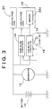
- FIG. 3 shows a circuit configuration of a second embodiment according to the invention.
- the main converter 14 and the sub converter 16 are each connected to different loads.
- the main converter 14 is connected to a power system load of the low voltage load 22, while the sub converter 16 is connected to memory 22a of the low voltage load 22 which is a load different from the power system load.
- the same processes as that of FIG. 2 is applied.
- the ignition switch 18 When the ignition switch 18 is turned OFF, the main converter 14 that supplies electric power to the power system load of the low voltage load 22 is deactivated and the sub converter that supplies electric power to the memory 22a of the low voltage load 22 is activated to supply the dark current to the memory 22a.
- the ignition switch 18 is ON, the main converter 14 is ON and the sub converter 16 is OFF, similar to the first embodiment mentioned above.
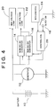
- FIG. 4 shows the circuit configuration of a third embodiment according to the invention.
- a keyless ECU (electronic control unit) 24 and a control ECU 26 are provided.
- the keyless ECU 24 and the control ECU 26 are fed with electric power from the sub converter 16 while in their stand-by states, and fed with electric power from the main converter 14 when the main switch 18 is ON.
- the keyless ECU 24 that detects operation (a door unlocking operation) of a transmitter carried by the operator, in a non-contact manner, detects unlocking of the doors of the vehicle. More specifically, the keyless ECU 24 that possesses an infrared detector detects a signal to unlock the doors transmitted by the transmitter. If the keyless ECU 24 detects unlocking of the doors while in the stand-by state maintained by electric power from the sub converter 16, the keyless ECU 24 sends a detection signal to the control ECU 26. An ON/OFF signal of the ignition switch 18 is also sent to the control ECU 26, and the control ECU controls operation of the main converter 14 and the sub converter 16 in accordance with these two detection signals.
- Fig. 5 shows a process flowchart of the third embodiment.
- the control ECU 24 detects a keyless door unlock (keyless unlock) signal while in the stand-by state maintained by electric power from the sub converter 16 (Step S201)
- the control ECU 24 supplies a control signal to the main converter 14.
- the control ECU 26 supplies the control signal to the main converter 14 that has been OFF, turning it from OFF to ON (Step S202).
- the control ECU 26 makes the main converter 14 reduce the high voltage (36V) of the battery 10 and supply it to the low voltage load 22 to effect unlocking of the door lock (Step S203).
- Step S204 After turning ON the main converter 14 to unlock the door lock, the control ECU 26 further judges whether or not the ignition switch 18 is turned ON. Normally, when the door lock is unlocked, it is most likely that the operator gets into the vehicle and turns ON the ignition switch 18. Therefore, when the ignition switch 18 is turned ON, the control ECU 26 supplies a control signal to the sub converter 16 to turn it OFF and at the same time maintains the main converter 14 in the ON state (Step S205).
- Step S206 the main converter 14 is turned from ON to OFF with a predetermined delay, specifically after the fixed amount of time.
- the reason for allowing a predetermined delay is because of consideration for the time necessary for the operator to operate the ignition switch 18. Note that also in this case, the sub converter 16 is ON as it was.
- the main converter 14 when there arises a need to operate the load independently from the ignition switch 18, the main converter 14 can be turned from OFF to ON to supply a specified amount of electric power to the load; thus the load can quickly be operated . Moreover, if the ignition switch 18 is not turned ON after that, the main converter 14 returns to the OFF state again; thus the capacity of the battery 10 is not unnecessarily reduced.
- Fig. 6 shows a circuit configuration of a fourth embodiment according to the invention.
- the main converter 14 and the sub converter 16 are each connected to different loads.
- the main converter 14 supplies electric power to the power system load of the low voltage load 22, and the sub converter 16 supplies the dark current to the memory 22a of the low voltage load 22.
- the same processes as those in FIG. 5 are applied.
- the sub converter 16 supplies the dark current to the memory 22a to retain the content of the memory.
- the main converter 14 is turned from OFF to ON to supply a specified amount of electric power to the power system load of the low voltage load 22.
- the sub converter 16 supplies the dark current to the low voltage load when the load is not being operated.
- the sub converter 16 may be turned ON to supply the load with a smaller amount of electric power than that for normal operation other than the dark current.
- the main converter 14 and the sub converter 16 are connected in parallel to each other and then connected to the low voltage load 22. It is also preferable that when the operation situation of the low voltage load 22 changes and there arises a need to operate the load with a lower amount of electric power than that for normal operation, the control ECU 26 detects this and turns the main converter 14 from ON to OFF while turning the sub converter 16 from OFF to ON.
- the control ECU 26 turns the main converter 14 from OFF to ON and turns the sub converter 16 from ON to OFF.
- this change may be done with a fixed delay, as in the already described embodiments, with a period of time provided when both DC-DC converters are ON.
- Fig. 7 shows the circuit block diagram of a fifth embodiment.
- a large-capacity DC-DC converter (main DC-DC converter) 14 and a small-capacity DC-DC converter (sub DC-DC converter) 16 are connected in parallel to the battery 10 whose voltage is 36 V.
- the large-capacity DC-DC converter 14 may have, for example, a capacity of 100 A and the small-capacity DC-DC converter 16 may have, for example, a capacity of 100 mA.
- the large-capacity DC-DC converter 14 and the small-capacity DC-DC converter 16 are both connected to a load 31, and supply it with a driving current and the dark current, respectively.
- a low-current detection circuit 30 and a voltage drop detection circuit 32 Connected between the load 31 and parallel connection of the large-capacity DC-DC converter 14 and the small-capacity DC-DC converter 16 is a low-current detection circuit 30 and a voltage drop detection circuit 32, which detect when an output current of the converters becomes equal to or less than a predetermined value (e.g., 100 mA) and when an output voltage becomes equal to or less than a predetermined value (e.g., 12 V), respectively, and output the detection signals, respectively.
- a predetermined value e.g. 100 mA
- a predetermined value e.g., 12 V
- the detection signal from the low current detection circuit 30 is sent to a delay processing circuit 34, and after specified processing at the delay processing circuit, is sent to an R terminal (reset terminal) of an RS flip-flop 36. Meanwhile, the detection signal from the voltage drop detection circuit 32 is sent to an S terminal (set terminal) of the RS flip-flop 36.
- the large-capacity DC-DC converter 14 When an enabling signal for controlling the activation of the large-capacity DC-DC converter 14 is sent from a Q output terminal of the RS flip-flop 36, specifically, when a High signal is outputted from a Q terminal, the large-capacity DC-DC converter 14 is activated. When a Low signal is outputted from the Q terminal, the large-capacity DC-DC converter 14 is deactivated. Therefore, when a signal is sent to the R terminal from the delay processing circuit 34, the Low signal is outputted from the Q terminal to deactivate of the large-capacity DC-DC converter 14, such that only the small-capacity DC-DC converter 16 is activated to supply electric power to the load 31.
- the High signal is sent from the Q terminal to effect activation of the large-capacity DC-DC converter 14, such that electric power is supplied to the load 31 by two converters, being the large-capacity DC-DC converter 14 and the small-capacity converter 16.
- the delay processing circuit 34 when the delay processing circuit 34 is supplied with a detection signal indicating that the output current has dropped equal to or less than a predetermined value at the low current detection circuit 30, the delay processing circuit 34 delays the detection signal by a predetermined time and outputs it. More specifically, when the output signal of only a fixed period of time is output from the low current detection current 30, that is, when the continuously output current of only a fixed period of time becomes equal to or less than a predetermined value, the delay processing circuit 34 outputs that output current.
- a circuit can be composed of a switching transistor, a capacitor, and a comparator.
- the delay processing circuit 34 should be configured in such way that when a detection signal is continuously outputted from the low current detection circuit 30 for a fixed period of time, the switching transistor is turned OFF to charge the condenser, and when a voltage of the capacitor terminal rises to so as be equal to or greater than a threshold value, the comparator outputs a signal.
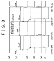
- a line (a) indicates an output voltage of the converter. while a line (b) indicates an output current of the converter.
- the output current decreases abruptly (e.g., from 30 A to 10 mA). This decrease of the current value is detected by the low current detection circuit 30, and, as shown by a line (c), a detection signal maintained in the high state only for a period when the output current decreases to 10 mA is outputted to the delay processing circuit 34.
- the delay processing circuit 34 Since the delay processing circuit 34 outputs a signal maintained in the high state only when the detection signal is sent from the low current detection circuit 30 continuously for the fixed period of time as described above, the delay processing circuit 34 outputs the High signal, which is delayed by a fixed amount of time with respect to the line (c), as shown by a line (d), to the RS flip-flop 36.
- the reason that the delay processing circuit 34 outputs the High signal when the detection signal is inputted thereto continuously for only the fixed amount of time is to reliably prevent a situation in which the large-capacity DC-DC converter 14 is erroneously deactivated in the case where the current value is temporarily decreased by noise at precisely the time when the large-capacity DC-DC converter 14 should be originally activated.
- the Q terminal of the RS flip-flop terminal 36 changes from High to Low as shown by a line (f), and as a result the large-capacity DC-DC converter 14 terminates its operation after the fixed amount of time after the ignition key was turned to OFF. Thus, the dark current supply to the load is carried out through the small-capacity DC-DC converter 16.
- the output current increases up to 10 A and at the same time the output voltage decreases down to 12 V or less because the output exceeds an output range of the small-capacity DC-DC converter 16.
- the signal from the low current detection circuit 30 changes from High to Low as shown by the line (c)
- the signal from the delay processing circuit 34 also changes from High to Low as shown by the line (d) . Note that in the delay processing circuit 34, when the signal rises from Low to High, there exists the fixed delay time for the change to take place as described above, but when the signal falls from High to Low, there is no delay.
- the voltage drop detection circuit 32 detects a drop in the output voltage and outputs a detection signal, as shown in a line (e), which is supplied to the S terminal of the RS flip-flop 36.
- a detection signal as shown in a line (e)
- the High signal is outputted from the Q terminal of the RS flip-flop 36 to effect activation of the large-capacity DC-DC converter 14, which supplies electric power required to turn on the light bulb.
- the Low signal is sent to the R terminal of the RS flip-flop 36 from the delay processing circuit 34 as shown by the line (d)
- the High signal is sent to the S terminal of the RS flip-flop 36 from the voltage drop detection circuit 32 as shown-by the line (e)
- the Q terminal changes from Low to High to effect activation of the large-capacity DC-DC converter 14 again, which changes the voltage of the battery 10 and supplies it to the load 31.
- the output current when the driver turns ON the hazard lights after turning the ignition key to OFF, the output current repeatedly increases and decreases in short cycles (e.g. in intervals of about one second or so) .
- a delay time at the delay processing circuit 34 to be longer than this time, a situation in which the large-capacity DC-DC converter 14 repeatedly turns ON and OFF in response to blinking of the hazard lights can reliably be prevented (the Q terminal will not become Low unless the output current is equal to or less than a predetermined value for a fixed continuation time), and thus variation of the output voltage can be prevented.
- the large-capacity DC-DC converter 14 turns OFF after the fixed amount of time such that only the small-capacity DC-DC converter 16 supplies the dark current, thereby suppressing power consumption by the large-capacity DC-DC converter 14.
- the large-capacity DC-DC converter 14 turns ON to supply the driving current. This obviates the need to additionally provide a low voltage (e.g. 12 V) battery for supplying the dark current and reduces the weight when this power supply is to be installed in a vehicle (because the weight of the small-capacity DC-DC converter 16 can be reduced considerably compared to the low voltage battery) .
- the small-capacity DC-DC converter 16 may either be activated or deactivated.
- the required electric power can be supplied to the load while suppressing the capacity reduction of the battery.
Landscapes
- Engineering & Computer Science (AREA)
- Power Engineering (AREA)
- Mechanical Engineering (AREA)
- Transportation (AREA)
- Sustainable Energy (AREA)
- Life Sciences & Earth Sciences (AREA)
- Sustainable Development (AREA)
- Business, Economics & Management (AREA)
- Emergency Management (AREA)
- Charge And Discharge Circuits For Batteries Or The Like (AREA)
- Direct Current Feeding And Distribution (AREA)
- Dc-Dc Converters (AREA)
- Ignition Installations For Internal Combustion Engines (AREA)
Abstract
Description
Claims (13)
- A power supply circuit for a vehicle that supplies electric power to a load (22), characterized by having:a battery (10);first converting means (14) for changing a voltage of the battery (10) and supplying main electric power to the load (22); andsecond converting means (16) for changing the voltage of the battery (10) and supplying auxiliary electric power to the load (22).
- A power supply circuit according to claim 1, characterized in that:the load (22) comprises a first load (22) and a second load (22a),the first converting means (14) supplies the main electric power to the first load (22), and the second converting means (16) supplies the auxiliary electric power to the second load (22a).
- A power supply circuit according to claim 1, characterized in that:
the first converting means (14) and the second converting means are connected-in parallel to each other and then connected to the load (22). - A power supply circuit according to either claim 2 or claim 3, characterized in that:
when a system switch that operates the load (22) is turned ON, the first converting means (14) is activated and when the system switch is turned OFF, the second converting means (16) is activated. - A power supply circuit according to claim 4, characterized in that:
when the system switch changes from ON to OFF, the first converting means (14) changes from being activated to being deactivated with a predetermined delay. - A power supply circuit according to either claim 2 or claim 3, characterized in that:when the system switch that operates the load (22) is turned OFF, the second converting means(16) is activated,and when the load (22) is activated independently of the system switch, the first converting means (14) is activated.
- A power supply circuit according to claim 6, characterized in that:
when the system switch is OFF, the first converting means (14) is deactivated with a predetermined delay after the activation. - A power supply circuit according to claim 1, characterized by further having:means (26) for detecting output currents of the first converting means (14) and the second converting means (16), andmeans (26) for deactivating the first converting means (14) when the output current is continuously equal to or less than a predetermined value for a fixed amount of time.
- A power supply circuit according to claim 3, characterized by further having:means (26) for detecting output voltages of the first converting means (14) and the second converting means (16),means (26) for activating the first converting means (14) when the output voltage becomes equal to or less than a predetermined value.
- A power supply circuit according to any one of claims 1 through 9, characterized in that:
the first converting means (14) has a larger capacity than the second converting means (16). - A power supply circuit according to any one of claims 4 through 7, characterized in that:
the system switch is an ignition switch of a vehicle. - A power supply circuit according to claim 1, characterized in that:
the first converting means (14) and the second converting means (16) are connected in parallel to each other and then connected to the load-(22), and the first converting means (14) and the second converting means (16) are activated alternately in accordance with an operation situation of the load (22). - A power supply circuit according to any one of claims 1 through 12, characterized in that:
the auxiliary electric power is electric power required when the load is nor being operated.
Applications Claiming Priority (4)
| Application Number | Priority Date | Filing Date | Title |
|---|---|---|---|
| JP2000004944 | 2000-01-13 | ||
| JP2000004944 | 2000-01-13 | ||
| JP2000156547 | 2000-05-26 | ||
| JP2000156547A JP2001268787A (en) | 2000-01-13 | 2000-05-26 | Power circuit |
Publications (2)
| Publication Number | Publication Date |
|---|---|
| EP1120880A2 true EP1120880A2 (en) | 2001-08-01 |
| EP1120880A3 EP1120880A3 (en) | 2004-06-09 |
Family
ID=26583460
Family Applications (1)
| Application Number | Title | Priority Date | Filing Date |
|---|---|---|---|
| EP01100460A Withdrawn EP1120880A3 (en) | 2000-01-13 | 2001-01-08 | Power supply circuit |
Country Status (4)
| Country | Link |
|---|---|
| EP (1) | EP1120880A3 (en) |
| JP (1) | JP2001268787A (en) |
| KR (1) | KR20010076256A (en) |
| CN (1) | CN1305912A (en) |
Cited By (6)
| Publication number | Priority date | Publication date | Assignee | Title |
|---|---|---|---|---|
| WO2002087068A1 (en) * | 2001-04-24 | 2002-10-31 | Robert Bosch Gmbh | Device for power supply in a multi-voltage electric system of a motor vehicle |
| DE102007001673A1 (en) * | 2007-01-11 | 2008-07-17 | Bayerische Motoren Werke Aktiengesellschaft | On-board electrical system for motor vehicle, has high volt energy storage, and converter device provided parallel to another converter device, and to allow preset energy application to take place in low-volt voltage network |
| CN110303907A (en) * | 2018-03-06 | 2019-10-08 | 现代自动车株式会社 | The electric power supply system and its control method of vehicle |
| US10836257B2 (en) | 2017-02-28 | 2020-11-17 | Denso Corporation | Control apparatus and control system including the same |
| CN115071452A (en) * | 2021-03-01 | 2022-09-20 | 沃尔沃汽车公司 | Battery architecture without low-voltage battery |
| WO2024068065A1 (en) * | 2022-09-27 | 2024-04-04 | Robert Bosch Gmbh | Dc voltage converter arrangement, electric vehicle and method for operating a dc voltage converter arrangement |
Families Citing this family (20)
| Publication number | Priority date | Publication date | Assignee | Title |
|---|---|---|---|---|
| JP3860484B2 (en) | 2002-02-15 | 2006-12-20 | 株式会社東芝 | Power management device |
| JP2005059712A (en) * | 2003-08-11 | 2005-03-10 | Auto Network Gijutsu Kenkyusho:Kk | Power supply device, fuse box, relay box, connector |
| JP4708817B2 (en) * | 2005-03-08 | 2011-06-22 | 株式会社オートネットワーク技術研究所 | Vehicle power supply system |
| JP4279854B2 (en) * | 2006-06-28 | 2009-06-17 | トヨタ自動車株式会社 | Vehicle power supply control device |
| DE102006036425A1 (en) * | 2006-08-04 | 2008-02-07 | Bayerische Motoren Werke Ag | System for supplying power to electrical consumers of a motor vehicle |
| JP5125155B2 (en) * | 2007-03-07 | 2013-01-23 | トヨタ自動車株式会社 | Power supply control device and power supply control method |
| JP5487817B2 (en) * | 2009-09-04 | 2014-05-14 | 株式会社オートネットワーク技術研究所 | Auxiliary battery power supply system and auxiliary battery power supply method |
| CN101860071B (en) * | 2010-05-11 | 2013-09-04 | 江苏宗申三轮摩托车制造有限公司 | City power supply module |
| CN102229327B (en) * | 2011-04-27 | 2014-03-19 | 北京启明精华新技术有限公司 | Automobile power supply system |
| CN103091632A (en) * | 2011-10-27 | 2013-05-08 | 现代摩比斯株式会社 | Automotive battery sensor and control method thereof |
| KR101315773B1 (en) * | 2012-05-03 | 2013-10-10 | 현대자동차주식회사 | Dark current cut off system and method for smart junction box of vehicle |
| JP6234127B2 (en) * | 2012-10-11 | 2017-11-22 | 株式会社Gsユアサ | Power storage device |
| WO2018012168A1 (en) * | 2016-07-13 | 2018-01-18 | 日立オートモティブシステムズ株式会社 | Electronic control device |
| JP6673138B2 (en) * | 2016-10-19 | 2020-03-25 | 株式会社オートネットワーク技術研究所 | Backup device for vehicles |
| JP6665762B2 (en) * | 2016-11-25 | 2020-03-13 | トヨタ車体株式会社 | Vehicle power system |
| JP6690560B2 (en) * | 2017-01-19 | 2020-04-28 | 株式会社オートネットワーク技術研究所 | In-vehicle power supply device |
| JP6826462B2 (en) * | 2017-02-28 | 2021-02-03 | 株式会社デンソー | Control system equipped with a control device and a control device |
| JP7028672B2 (en) * | 2018-02-20 | 2022-03-02 | 株式会社三社電機製作所 | Power supply |
| DE102019213073A1 (en) * | 2019-08-30 | 2021-03-04 | Robert Bosch Gmbh | Procedure for operating voltage converters connected in parallel |
| CN114475253A (en) * | 2022-02-22 | 2022-05-13 | 山东丽驰新能源汽车有限公司 | Power supply system and power supply method for power battery internal controller |
Family Cites Families (4)
| Publication number | Priority date | Publication date | Assignee | Title |
|---|---|---|---|---|
| JPS60258620A (en) * | 1984-06-05 | 1985-12-20 | Canon Inc | Power supply device |
| JPH0433522A (en) * | 1990-05-30 | 1992-02-04 | Fujitsu Ltd | Dc/dc converter device |
| JP3761966B2 (en) * | 1996-04-22 | 2006-03-29 | 富士重工業株式会社 | Electric vehicle power system |
| GB2332105B (en) * | 1997-12-03 | 2000-01-26 | Samsung Electronics Co Ltd | Power supply |
-
2000
- 2000-05-26 JP JP2000156547A patent/JP2001268787A/en active Pending
-
2001
- 2001-01-08 EP EP01100460A patent/EP1120880A3/en not_active Withdrawn
- 2001-01-12 CN CN01101262A patent/CN1305912A/en active Pending
- 2001-01-12 KR KR1020010001769A patent/KR20010076256A/en not_active Ceased
Cited By (7)
| Publication number | Priority date | Publication date | Assignee | Title |
|---|---|---|---|---|
| WO2002087068A1 (en) * | 2001-04-24 | 2002-10-31 | Robert Bosch Gmbh | Device for power supply in a multi-voltage electric system of a motor vehicle |
| DE102007001673A1 (en) * | 2007-01-11 | 2008-07-17 | Bayerische Motoren Werke Aktiengesellschaft | On-board electrical system for motor vehicle, has high volt energy storage, and converter device provided parallel to another converter device, and to allow preset energy application to take place in low-volt voltage network |
| US10836257B2 (en) | 2017-02-28 | 2020-11-17 | Denso Corporation | Control apparatus and control system including the same |
| CN110303907A (en) * | 2018-03-06 | 2019-10-08 | 现代自动车株式会社 | The electric power supply system and its control method of vehicle |
| CN110303907B (en) * | 2018-03-06 | 2024-03-01 | 现代自动车株式会社 | Vehicle power supply system and control method thereof |
| CN115071452A (en) * | 2021-03-01 | 2022-09-20 | 沃尔沃汽车公司 | Battery architecture without low-voltage battery |
| WO2024068065A1 (en) * | 2022-09-27 | 2024-04-04 | Robert Bosch Gmbh | Dc voltage converter arrangement, electric vehicle and method for operating a dc voltage converter arrangement |
Also Published As
| Publication number | Publication date |
|---|---|
| CN1305912A (en) | 2001-08-01 |
| KR20010076256A (en) | 2001-08-11 |
| JP2001268787A (en) | 2001-09-28 |
| EP1120880A3 (en) | 2004-06-09 |
Similar Documents
| Publication | Publication Date | Title |
|---|---|---|
| US6400589B2 (en) | Control apparatus for a power supply circuit including plural converter | |
| EP1120880A2 (en) | Power supply circuit | |
| US10889201B2 (en) | Power redundancy system | |
| CN100417549C (en) | Safety switch for accumulator | |
| US6838783B2 (en) | Wake up system for electronic component supported on a vehicle | |
| US10763693B2 (en) | Back-up power source device and back-up system | |
| US20200343763A1 (en) | Power supply system | |
| US6762945B2 (en) | Method and system for producing a supply voltage during a first and second operating mode | |
| US6762595B2 (en) | Power distribution system | |
| US9862239B2 (en) | Antenna driving device | |
| US7689335B2 (en) | Highly reliable vehicle system start controller | |
| US6509767B2 (en) | Wake-up circuit | |
| JP6201750B2 (en) | Power supply for vehicle | |
| WO2018056190A1 (en) | Power source device and vehicle equipped with power source device | |
| US20090102434A1 (en) | Auxiliary power supply device for vehicle, power supply device for vehicle, having the auxiliary power supply device, and automobile | |
| US6329791B1 (en) | Power supply system and control method for the system | |
| JPWO2018180606A1 (en) | Vehicle-mounted power supply device and vehicle on which the vehicle-mounted power supply device is mounted | |
| JP6773192B2 (en) | Backup power supply and backup system | |
| JP2020204410A (en) | Backup power source device and backup system | |
| EP0697312A1 (en) | Electric current control circuit for switches | |
| JP2699865B2 (en) | Power supply system for in-vehicle portable wireless telephone | |
| JP6604312B2 (en) | Power control device | |
| US20260109360A1 (en) | Onboard backup control device | |
| JP7809260B2 (en) | Vehicle backup device | |
| US20220416318A1 (en) | In-Vehicle Power Source Control Apparatus and In-Vehicle Power Source Apparatus |
Legal Events
| Date | Code | Title | Description |
|---|---|---|---|
| PUAI | Public reference made under article 153(3) epc to a published international application that has entered the european phase |
Free format text: ORIGINAL CODE: 0009012 |
|
| 17P | Request for examination filed |
Effective date: 20010206 |
|
| AK | Designated contracting states |
Kind code of ref document: A2 Designated state(s): AT BE CH CY DE DK ES FI FR GB GR IE IT LI LU MC NL PT SE TR |
|
| AX | Request for extension of the european patent |
Free format text: AL;LT;LV;MK;RO;SI |
|
| PUAL | Search report despatched |
Free format text: ORIGINAL CODE: 0009013 |
|
| AK | Designated contracting states |
Kind code of ref document: A3 Designated state(s): AT BE CH CY DE DK ES FI FR GB GR IE IT LI LU MC NL PT SE TR |
|
| AX | Request for extension of the european patent |
Extension state: AL LT LV MK RO SI |
|
| RIC1 | Information provided on ipc code assigned before grant |
Ipc: 7H 02J 7/00 B Ipc: 7B 60L 1/00 A |
|
| STAA | Information on the status of an ep patent application or granted ep patent |
Free format text: STATUS: THE APPLICATION HAS BEEN WITHDRAWN |
|
| 18W | Application withdrawn |
Effective date: 20040615 |