EP1122120A1 - Juvenile safety car seat - Google Patents
Juvenile safety car seat Download PDFInfo
- Publication number
- EP1122120A1 EP1122120A1 EP01300313A EP01300313A EP1122120A1 EP 1122120 A1 EP1122120 A1 EP 1122120A1 EP 01300313 A EP01300313 A EP 01300313A EP 01300313 A EP01300313 A EP 01300313A EP 1122120 A1 EP1122120 A1 EP 1122120A1
- Authority
- EP
- European Patent Office
- Prior art keywords
- side guards
- juvenile
- car seat
- backrest portion
- safety car
- Prior art date
- Legal status (The legal status is an assumption and is not a legal conclusion. Google has not performed a legal analysis and makes no representation as to the accuracy of the status listed.)
- Withdrawn
Links
- 230000000366 juvenile effect Effects 0.000 title claims abstract description 76
- 230000007246 mechanism Effects 0.000 claims abstract description 37
- 230000012010 growth Effects 0.000 claims description 8
- 230000009599 head growth Effects 0.000 claims 1
- 238000009877 rendering Methods 0.000 description 2
- 101100313164 Caenorhabditis elegans sea-1 gene Proteins 0.000 description 1
- 239000003086 colorant Substances 0.000 description 1
- 238000006073 displacement reaction Methods 0.000 description 1
- 230000002401 inhibitory effect Effects 0.000 description 1
- 238000000034 method Methods 0.000 description 1
Images






Classifications
-
- B—PERFORMING OPERATIONS; TRANSPORTING
- B60—VEHICLES IN GENERAL
- B60N—SEATS SPECIALLY ADAPTED FOR VEHICLES; VEHICLE PASSENGER ACCOMMODATION NOT OTHERWISE PROVIDED FOR
- B60N2/00—Seats specially adapted for vehicles; Arrangement or mounting of seats in vehicles
- B60N2/24—Seats specially adapted for vehicles; Arrangement or mounting of seats in vehicles for particular purposes or particular vehicles
- B60N2/26—Seats specially adapted for vehicles; Arrangement or mounting of seats in vehicles for particular purposes or particular vehicles for children
-
- B—PERFORMING OPERATIONS; TRANSPORTING
- B60—VEHICLES IN GENERAL
- B60N—SEATS SPECIALLY ADAPTED FOR VEHICLES; VEHICLE PASSENGER ACCOMMODATION NOT OTHERWISE PROVIDED FOR
- B60N2/00—Seats specially adapted for vehicles; Arrangement or mounting of seats in vehicles
- B60N2/24—Seats specially adapted for vehicles; Arrangement or mounting of seats in vehicles for particular purposes or particular vehicles
- B60N2/26—Seats specially adapted for vehicles; Arrangement or mounting of seats in vehicles for particular purposes or particular vehicles for children
- B60N2/28—Seats readily mountable on, and dismountable from, existing seats or other parts of the vehicle
- B60N2/2857—Seats readily mountable on, and dismountable from, existing seats or other parts of the vehicle characterised by the peculiar orientation of the child
- B60N2/286—Seats readily mountable on, and dismountable from, existing seats or other parts of the vehicle characterised by the peculiar orientation of the child forward facing
-
- B—PERFORMING OPERATIONS; TRANSPORTING
- B60—VEHICLES IN GENERAL
- B60N—SEATS SPECIALLY ADAPTED FOR VEHICLES; VEHICLE PASSENGER ACCOMMODATION NOT OTHERWISE PROVIDED FOR
- B60N2/00—Seats specially adapted for vehicles; Arrangement or mounting of seats in vehicles
- B60N2/24—Seats specially adapted for vehicles; Arrangement or mounting of seats in vehicles for particular purposes or particular vehicles
- B60N2/26—Seats specially adapted for vehicles; Arrangement or mounting of seats in vehicles for particular purposes or particular vehicles for children
- B60N2/28—Seats readily mountable on, and dismountable from, existing seats or other parts of the vehicle
- B60N2/2839—Seats readily mountable on, and dismountable from, existing seats or other parts of the vehicle having a front guard or barrier
-
- B—PERFORMING OPERATIONS; TRANSPORTING
- B60—VEHICLES IN GENERAL
- B60N—SEATS SPECIALLY ADAPTED FOR VEHICLES; VEHICLE PASSENGER ACCOMMODATION NOT OTHERWISE PROVIDED FOR
- B60N2/00—Seats specially adapted for vehicles; Arrangement or mounting of seats in vehicles
- B60N2/24—Seats specially adapted for vehicles; Arrangement or mounting of seats in vehicles for particular purposes or particular vehicles
- B60N2/26—Seats specially adapted for vehicles; Arrangement or mounting of seats in vehicles for particular purposes or particular vehicles for children
- B60N2/28—Seats readily mountable on, and dismountable from, existing seats or other parts of the vehicle
- B60N2/2866—Seats readily mountable on, and dismountable from, existing seats or other parts of the vehicle booster cushions, e.g. to lift a child to allow proper use of the conventional safety belts
-
- B—PERFORMING OPERATIONS; TRANSPORTING
- B60—VEHICLES IN GENERAL
- B60N—SEATS SPECIALLY ADAPTED FOR VEHICLES; VEHICLE PASSENGER ACCOMMODATION NOT OTHERWISE PROVIDED FOR
- B60N2/00—Seats specially adapted for vehicles; Arrangement or mounting of seats in vehicles
- B60N2/24—Seats specially adapted for vehicles; Arrangement or mounting of seats in vehicles for particular purposes or particular vehicles
- B60N2/26—Seats specially adapted for vehicles; Arrangement or mounting of seats in vehicles for particular purposes or particular vehicles for children
- B60N2/28—Seats readily mountable on, and dismountable from, existing seats or other parts of the vehicle
- B60N2/2872—Seats readily mountable on, and dismountable from, existing seats or other parts of the vehicle provided with side rests
Definitions
- the present invention relates to a juvenile safety car seat, and more specifically, it relates to the structure of a child & junior seat comprising a seat portion and a backrest portion for supporting a juvenile.
- a juvenile safety car seat fixed with a seat belt provided on a car for supporting a juvenile (including a neonate, a baby, an infant and a schoolchild) with a safety belt provided on the juvenile safety car seat is generally referred to as a baby & child seat
- another juvenile safety car seat fixed to a seat of a car along with a juvenile with a seat belt provided on the car is generally referred to as a junior seat
- Still another juvenile safety car seat referred to as a child & junior seat is also developed as that having both supporting methods.
- An object of the present invention is to provide a juvenile safety car seat excellent in safety and comfortableness.
- a juvenile safety car seat comprising a seat portion and a backrest portion for supporting a juvenile in a car, comprises a pair of side guards outwardly movably provided on both sides of the aforementioned backrest portion for protecting the head region and the shoulder regions of the aforementioned juvenile.
- a support space can be brought into the optimum state in response to growth of the head region and the shoulder regions of the juvenile due to the provision of the outwardly movable side guards. Consequently, the juvenile safety car seat can be improved in safety and comfortableness.
- the aforementioned side guards are preferably provided to be capable of increasing the distances between the side guards and the aforementioned shoulder regions of the aforementioned juvenile while keeping the distances between the side guards and the aforementioned head region of the aforementioned juvenile substantially constant.
- the aforementioned side guards are so mounted that upper end regions are rotatable with respect to the aforementioned backrest portion for outwardly opening lower end regions of the aforementioned side guards.
- the shoulder portions (the breadth of the shoulders) of the juvenile grow at a higher degree than the head portion. Therefore, the support space for the juvenile can be optimally changed by providing the lower end regions of the side guards coming into contact with the shoulder portions to be outwardly openable, thereby further improving the safety and comfortableness of the juvenile safety car seat.
- the aforementioned side guards are preferably provided with an interlocking link mechanism for simultaneously enabling adjustment of the interval between the side guards.
- the aforementioned interlocking link mechanism preferably includes a mechanism for outwardly opening only lower end regions of the aforementioned side guards.
- the side guards can be simultaneously adjusted by employing this mechanism, thereby improving handleability of the juvenile safety car seat.
- the aforementioned side guards preferably have upper side guards and lower side guards respectively.
- a proper space responsive to the shapes of the head region and the shoulder regions of the juvenile can be defined due to this structure, whereby the juvenile safety car seat can protect the juvenile in a more preferable state.
- the juvenile safety car seat is preferably so provided that the quantity of outward movement of the aforementioned lower side guards is greater than the quantity of outward movement of the aforementioned upper side guards.
- the shoulder portions (the breadth of the shoulders) of the juvenile grow at a higher degree than the head portion. Therefore, the support space for the juvenile can be optimally changed in response to the growth of the juvenile for further improving the safety and comfortableness of the juvenile safety car seat.
- the aforementioned upper side guards and the aforementioned lower side guards are preferably provided with interlocking link mechanisms for simultaneously enabling adjustment of the intervals between the upper side guards and the lower side guards respectively.
- interlocking link mechanisms for simultaneously enabling adjustment of the intervals between the upper side guards and the lower side guards respectively.
- the juvenile safety car seat preferably further comprises a vertical position adjusting mechanism for adjusting the vertical position of the aforementioned backrest portion.
- the support space can be brought into the optimum state in response to growth of the height of the juvenile by providing this mechanism.
- the aforementioned vertical position adjusting mechanism preferably includes a plate fixed to the aforementioned seat portion and provided to upwardly extend, a guide region provided on the aforementioned backrest portion for guiding the aforementioned plate so that the aforementioned backrest portion is vertically slidable along the aforementioned plate and a fixing device for fixing a selected vertical position of the aforementioned backrest portion.
- the aforementioned guide region has a receiving space for receiving the aforementioned plate in the range of the thickness of the aforementioned backrest portion.
- the backrest portion is vertically slidable along the plate due to this structure, so that the vertical position of the backrest portion can be readily adjusted.
- the aforementioned fixing device preferably includes an elastic member provided on either one of the aforementioned plate and the aforementioned guide region and a plurality of engaging regions vertically provided on the other one of the plate and the guide region for engaging with the aforementioned elastic member.
- the elastic member engages with any of the engaging regions on the basis of the elastic force thereof for fixing the plate and the guiding region, thereby fixing the vertical position of the backrest portion.
- the engaging regions are moved against the elastic force of the elastic member so that the elastic member successively engages with the engaging regions, whereby the backrest portion can be fixed on a desired vertical position.
- regions coming into contact with the aforementioned head region of the aforementioned juvenile and regions coming into contact with the aforementioned shoulder regions are visually partitioned in the aforementioned side guards.
- the juvenile safety car seat can provide a sense of security to the user, thereby improving comfortableness for the user.
- Fig. 1 is a perspective view showing the overall structure of the child & junior seat 1.
- This child & junior seat 1 comprises a seat portion 100 and a backrest portion 200 forming a support portion defining a support space for receiving a juvenile.
- the seat portion 100 has a seat body 111 and an adjusting member 112 for adjusting the vertical position of a seat belt (not shown) provided on a car.
- the backrest portion 200 includes a head guard region 251 and a backrest region 253, and guide slits 252 for receiving the seat belt (not shown) provided on the car are provided on both sides of the backrest portion 200.
- a pair of side guards 210 are outwardly movably provided on both sides of the backrest portion 200, in order to protect the head region and the shoulder regions of a juvenile.
- Each side guard 210 includes a head protecting pad region 210 protecting the head region of the juvenile and a shoulder protecting pad region 212 largely extending downward from the head protecting pad region 211 for protecting each shoulder region of the juvenile.
- a vertical position adjusting mechanism (described later) for adjusting the vertical position of the backrest portion 200 is provided between the seat portion 100 and the backrest portion 200.
- Fig. 2 is a total perspective view showing the child & junior seat 1 in a state outwardly spreading the side guards 210 along arrows
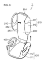
- Fig. 3 is a total perspective view showing the child & junior seat 1 in a state pulling up the backrest portion 200 along arrow.
- the support space can be brought into the optimum state in response to growth of the head region, the shoulder regions and the height of the juvenile by employing the mechanism rendering the side guards 210 outwardly spreadable and the mechanism rendering the vertical position of the backrest portion 200 adjustable, thereby improving safety and comfortableness of the child & junior seat 1.
- FIG. 4 is a sectional view taken along the line IV in Fig. 1
- Fig. 5 is a front elevational view showing the child & junior seat 1 in a state closing the side guards 210
- an Fig. 6 is a front elevational view showing the child & junior seat 1 in a state opening the side guards 210. While the child & junior seat 1 is covered with a cushion member or the like in Figs. 1 to 3, it is assumed that such a cushion member or the like is detached from the child & junior seat 1 in Figs. 4 to 6 for convenience of illustration.
- the interlocking link mechanism 220 A is provided with side guard frames 221 supporting the side guards 210.
- the side guard frames 221 are fixed on upper end portions to be rotatable at pivot portions 223 provided on a backrest frame 222 of the backrest portion 200, for outwardly opening lower ends of the side guards 210.
- First ends of link bars 226 are rotatably fixed to intermediate regions of the side guard frames 221 through pivot portions 227. Second ends of the link bars 226 are fixed to an adjusting nut 228 movable along a vertical slot 229 provided on the backrest frame 222 for selecting position control.
- the side guard frames 221 are provided with arcuate slots 224 along the tracks of the side guards 210 for limiting the quantities of movement of the side guards 210, and shafts 225 provided on the backrest frame 222 are inserted in these slots 224.
- the side guards 210 are most closed as shown in Fig. 5.
- the link bars 226 simultaneously spread the side guards 210 outward as shown in Fig. 6.
- the side guards 210 can be simultaneously adjusted by providing the aforementioned interlocking link mechanism 220A, thereby improving handleability of the child & junior seat 1.
- the shoulder portions (the breadth of the shoulders) of the juvenile grow at a higher degree than the head portion. Therefore, the support space for the juvenile can be optimally changed by providing the lower end regions of the side guards 210 coming into contact with the shoulder portions to be outwardly openable, thereby further improving the safety and comfortableness of the juvenile safety car seat.
- Fig. 7 is a rear elevational view of a lower end region 250 of the backrest portion 200
- Fig. 8 is a sectional view taken along the line VIII-VIII in Fig. 7.
- Fig. 9 is a rear elevational view of a plate 260 detachably provided on the seat portion 100
- Fig. 10 is a sectional view taken along the line X-X in Fig. 9.
- the lower end region 250 of the backrest portion 200 has a guide region defining a space for receiving the plate 260, and this guide region includes a first region 255a substantially identical in width to the plate 260 and a second region 255b larger in width than the first region 255a.
- a pair of engaging regions 254 consisting of corrugated irregularities along the vertical direction are provided on the back surface of the guide region.
- an upper region 261 of the plate 260 has a pair of tongue-shaped elastic plates 263 provided on forward ends thereof with convex portions 264 engaging with the engaging regions 254.
- the plate 260 is further provided on its upper end with an outwardly spreading wide portion 262 engaging with the boundary between the first and second regions 255a and 255b of the guide region for preventing displacement of the backrest portion 200 from the plate 260.
- Fig. 11 illustrates the backrest portion 200 inserted in the plate 260
- Fig. 12 is a sectional view taken along the line XII-XII in Fig. 11.
- the convex portions 264 of the elastic plates 263 engage with the uppermost ends of the engaging regions 254 when the backrest portion 200 is located on the lowermost position.
- Fig. 13 shows the backrest portion 200 in an upwardly pulled state
- Fig. 14 is a sectional view taken along the line XIV-XIV in Fig. 13.
- the convex potions 264 of the elastic plates 263 engage with prescribed regions of the engaging regions 254 when the backrest portion 200 is upwardly pulled, for inhibiting the backrest portion 200 from downward movement on the basis of the elastic force of the elastic plates 263.
- the plate 260 can be readily attached to/detached from the seat portion 100 by sliding fixing pins 270 provided on the lower end of the plate 260 against coil springs 271.
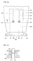
- sliding pins 280 extractable against coil springs 281 may alternatively be provided on the lower region 250 of the backrest portion 200 to be inserted in a plurality of location holes 282 provided along the vertical direction of the plate 260 for adjusting the vertical position of the backrest portion 200,a s shown in Figs. 15 and 16. Further, the aforementioned two mechanisms may be combined with each other for adjusting the vertical position of the backrest portion 200, as shown in Fig. 17.
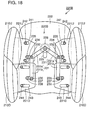
- Fig. 18 is a front elevational view showing the child & junior seat 1 according to this embodiment in a state closing the side guards
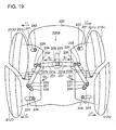
- Fig. 19 is a front elevational view showing the child & junior seat 1 in a state opening the side guards. It is assumed that Figs. 19 and 20 show a state detaching a cushion member or the like from the child & junior seat 1, for convenience of illustration.
- the side guards include upper side guards 210U protecting the head region of a juvenile and lower side guards 210D.
- the upper side guards 210U are provided with upper plates 221U, and guide pins 242 provided on a backrest frame 222 are engaged with guide holes 241 provided on the upper plates 221U so that the upper side guards 210U are transversely slidable.
- the lower side guards 210D are provided with lower plates 221D, and guide pins 244 provided on the frame 222 are engaged with guide holes 243 provided on the lower plates 221D so that the lower side guards 210D are transversely slidable.
- Link bars 231 couple the upper plates 221U and the lower plates 221D with each other. As shown in Fig. 18, the link bars 231 have V-shaped link plates 231a and 231b.
- An adjusting nut 228 movable along a vertical slot 229 provided on the backrest frame 222 for selecting position control is rotatably fixed to forward end portions of the link plates 231a.
- First ends of guide plates 234 are rotatably coupled to the cross points of the link plates 231a and 231b with pivot portions 232, and the upper plates 221U are rotatably coupled to second ends of the guide plates 234 with pivot portions 235.
- First ends of guide plates 237 are rotatably coupled to forward end portions of the link plates 231b with pivot portions 236, and the lower plates 221D are rotatably coupled to second ends of the guide plates 237 with pivot portions 238.
- the side guards 210U and 210U are most closed as shown in Fig. 18.
- the link bars 231 have the V-shaped link plates 231a and 231b, and hence the pivot potions 235 and 238 move by different quantities so that the quantity (L2) of outward movement of the lower side guards 210D is greater than the quantity (L2) of outward movement of the lower side guards 210U.
- the side guards 210U and 210D can be simultaneously adjusted by providing the aforementioned interlocking link mechanism 220B, for improving handleability of the child & junior seat 1.
- the shoulder portions (the breadth of the shoulders) of the juvenile grow at a higher degree than the head portion. Therefore, a support space for the juvenile can be optimally changed in response to growth of the juvenile by providing the lower side guards 210D coming into contact with the shoulder portions to be outwardly openable beyond the upper side guards 210U, for further improving the safety and comfortableness of the juvenile safety car seat.
- regions of the side guards 210 coming into contact with the head region of the juvenile and those coming into contact with the shoulder regions are preferably visually partitioned from each other.
- different colors may be supplied to the regions coming into contact with the head region and those coming into contact with the shoulder regions for clearly distinguishing the regions from each other, or lines may be provided on the boundaries between the regions coming into contact with the head region and those coming into contact with the shoulder regions.
- the child & junior seat 1 can supply a sense of security to the user, thereby improving comfortableness for the user.
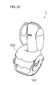
- the child & junior seat 1 When an impact shield 300 is provided as shown in Fig. 20 and the child & junior seat 1 according to each of the aforementioned embodiments is fixed with a seat belt provided on a car, the child & junior seat 1 can be employed as a child seat enabling a space between the impact shield 300, the seat portion 100 and the backrest portion 200 to support the juvenile.
- the backrest portion 200 is detached from the seat portion 100 as shown in Fig. 21, the child & junior seat 1 can be employed as a junior seat provided with only the seat portion 100.
- the support space can be brought into the optimum state in response to growth of the head region and the shoulder regions of the juvenile due to provision of the outwardly movable side guards.
- the support space can also be brought into the optimum state in response to growth of the height of the juvenile due to provision of the mechanism for adjusting the vertical position of the backrest portion. Consequently, the juvenile safety car seat can be improved in safety and comfortableness.
Landscapes
- Engineering & Computer Science (AREA)
- Health & Medical Sciences (AREA)
- Child & Adolescent Psychology (AREA)
- General Health & Medical Sciences (AREA)
- Aviation & Aerospace Engineering (AREA)
- Transportation (AREA)
- Mechanical Engineering (AREA)
- Seats For Vehicles (AREA)
- Automotive Seat Belt Assembly (AREA)
Abstract
A juvenile safety car seat comprises a seat portion (100) and a
backrest portion (200) forming a support portion defining a support space
for receiving a juvenile. A pair of side guards (210) are outwardly movably
provided on both sides of the backrest portion (200) for protecting the head
region and the shoulder regions of the juvenile. A vertical position
adjusting mechanism for adjusting the vertical position of the backrest
portion (200) is provided between the seat portion (100) and the backrest
portion (200). It is possible to provide a child & junior seat excellent in
safety and comfortableness by employing this structure.
Description
- The present invention relates to a juvenile safety car seat, and more specifically, it relates to the structure of a child & junior seat comprising a seat portion and a backrest portion for supporting a juvenile.
- A juvenile safety car seat fixed with a seat belt provided on a car for supporting a juvenile (including a neonate, a baby, an infant and a schoolchild) with a safety belt provided on the juvenile safety car seat is generally referred to as a baby & child seat, while another juvenile safety car seat fixed to a seat of a car along with a juvenile with a seat belt provided on the car is generally referred to as a junior seat. Still another juvenile safety car seat referred to as a child & junior seat is also developed as that having both supporting methods.
- While the baby & child seat is widely developed in general, school-age children are also obliged to use the juvenile safety car seat following revision of the Road Traffic Act, and it is urgently necessary to develop a child & junior seat also directed to school-age children with higher safety and comfortableness.
- An object of the present invention is to provide a juvenile safety car seat excellent in safety and comfortableness.
- A juvenile safety car seat according to the present invention, comprising a seat portion and a backrest portion for supporting a juvenile in a car, comprises a pair of side guards outwardly movably provided on both sides of the aforementioned backrest portion for protecting the head region and the shoulder regions of the aforementioned juvenile.
- According to the aforementioned structure of the present invention, a support space can be brought into the optimum state in response to growth of the head region and the shoulder regions of the juvenile due to the provision of the outwardly movable side guards. Consequently, the juvenile safety car seat can be improved in safety and comfortableness.
- According to the present invention, the aforementioned side guards are preferably provided to be capable of increasing the distances between the side guards and the aforementioned shoulder regions of the aforementioned juvenile while keeping the distances between the side guards and the aforementioned head region of the aforementioned juvenile substantially constant. As a specific mode, the aforementioned side guards are so mounted that upper end regions are rotatable with respect to the aforementioned backrest portion for outwardly opening lower end regions of the aforementioned side guards.
- From early childhood to school age, the shoulder portions (the breadth of the shoulders) of the juvenile grow at a higher degree than the head portion. Therefore, the support space for the juvenile can be optimally changed by providing the lower end regions of the side guards coming into contact with the shoulder portions to be outwardly openable, thereby further improving the safety and comfortableness of the juvenile safety car seat.
- According to the present invention, the aforementioned side guards are preferably provided with an interlocking link mechanism for simultaneously enabling adjustment of the interval between the side guards. According to the present invention, the aforementioned interlocking link mechanism preferably includes a mechanism for outwardly opening only lower end regions of the aforementioned side guards.
- The side guards can be simultaneously adjusted by employing this mechanism, thereby improving handleability of the juvenile safety car seat.
- According to the present invention, the aforementioned side guards preferably have upper side guards and lower side guards respectively.
- A proper space responsive to the shapes of the head region and the shoulder regions of the juvenile can be defined due to this structure, whereby the juvenile safety car seat can protect the juvenile in a more preferable state.
- According to the present invention, the juvenile safety car seat is preferably so provided that the quantity of outward movement of the aforementioned lower side guards is greater than the quantity of outward movement of the aforementioned upper side guards.
- From early childhood to school age, the shoulder portions (the breadth of the shoulders) of the juvenile grow at a higher degree than the head portion. Therefore, the support space for the juvenile can be optimally changed in response to the growth of the juvenile for further improving the safety and comfortableness of the juvenile safety car seat.
- According to the present invention, the aforementioned upper side guards and the aforementioned lower side guards are preferably provided with interlocking link mechanisms for simultaneously enabling adjustment of the intervals between the upper side guards and the lower side guards respectively. Thus, adjustability for the intervals between the side guards can be improved.
- According to the present invention, the juvenile safety car seat preferably further comprises a vertical position adjusting mechanism for adjusting the vertical position of the aforementioned backrest portion. The support space can be brought into the optimum state in response to growth of the height of the juvenile by providing this mechanism.
- According to the present invention, the aforementioned vertical position adjusting mechanism preferably includes a plate fixed to the aforementioned seat portion and provided to upwardly extend, a guide region provided on the aforementioned backrest portion for guiding the aforementioned plate so that the aforementioned backrest portion is vertically slidable along the aforementioned plate and a fixing device for fixing a selected vertical position of the aforementioned backrest portion. The aforementioned guide region has a receiving space for receiving the aforementioned plate in the range of the thickness of the aforementioned backrest portion.
- The backrest portion is vertically slidable along the plate due to this structure, so that the vertical position of the backrest portion can be readily adjusted.
- According to the present invention, the aforementioned fixing device preferably includes an elastic member provided on either one of the aforementioned plate and the aforementioned guide region and a plurality of engaging regions vertically provided on the other one of the plate and the guide region for engaging with the aforementioned elastic member.
- Thus, the elastic member engages with any of the engaging regions on the basis of the elastic force thereof for fixing the plate and the guiding region, thereby fixing the vertical position of the backrest portion. When adjusting the vertical position of the backrest portion, the engaging regions are moved against the elastic force of the elastic member so that the elastic member successively engages with the engaging regions, whereby the backrest portion can be fixed on a desired vertical position.
- According to the present invention, regions coming into contact with the aforementioned head region of the aforementioned juvenile and regions coming into contact with the aforementioned shoulder regions are visually partitioned in the aforementioned side guards. Thus, the juvenile safety car seat can provide a sense of security to the user, thereby improving comfortableness for the user.
- The foregoing and other objects, features, aspects and advantages of the present invention will become more apparent from the following detailed description of the present invention when taken in conjunction with the accompanying drawings.
-
- Fig. 1 is a perspective view showing the overall structure of a child &
junior seat 1 according to a first embodiment of the present invention; - Fig. 2 is a total perspective view showing the child &
junior seat 1 in a state outwardly spreadingside guards 210; - Fig. 3 is a total perspective view showing the child &
junior seat 1 in a state pulling up abackrest portion 200; - Fig. 4 is a sectional view taken along the line IV in Fig. 1;
- Fig. 5 is a front elevational view showing the child &
junior seat 1 in a state closing theside guards 210; - Fig. 6 is a front elevational view showing the child &
junior seat 1 in a state opening theside guards 210; - Fig. 7 is a rear elevational view of a
lower region 250 of thebackrest portion 200; - Fig. 8 is a sectional view taken along the line VIII-VIII in Fig. 7;
- Fig. 9 is a rear elevational view of a
plate 260 detachably provided on aseat portion 100; - Fig. 10 is a sectional view taken along the line X-X in Fig. 9;
- Fig. 11 illustrates the
backrest portion 200 inserted in theplate 260; - Fig. 12 is a sectional view taken along the line XII-XII in Fig. 11;
- Fig. 13 illustrates the
backrest portion 200 in an upwardly pulled state; - Fig. 14 is a sectional view taken along the line XIV-XIV in Fig. 13;
- Fig. 15 is a rear elevational view showing another vertical position adjusting mechanism;
- Fig. 16 is a sectional view taken along the line XVI in Fig. 15;
- Fig. 17 is a rear elevational view showing still another vertical position adjusting mechanism;
- Fig. 18 is a front elevational view showing a child &
junior seat 1 according to a second embodiment of the present invention in a stateclosing side guards - Fig. 19 is a front elevational view showing the child &
junior seat 1 according to the second embodiment of the present invention in a state opening theside guards - Fig. 20 is a perspective view showing the child &
junior seat 1 employed as a child seat; and - Fig. 21 is a perspective view showing the child &
junior seat 1 employed as a junior seat. -
- The structure of a juvenile safety car seat (hereinafter referred to as a child & junior seat) according to each embodiment of the present invention is now described with reference to the drawings.
- The structure of a child &
junior sea 1 according to a first embodiment of the present invention is now schematically described with reference to Fig. 1. Fig. 1 is a perspective view showing the overall structure of the child &junior seat 1. - This child &
junior seat 1 comprises aseat portion 100 and abackrest portion 200 forming a support portion defining a support space for receiving a juvenile. Theseat portion 100 has aseat body 111 and an adjustingmember 112 for adjusting the vertical position of a seat belt (not shown) provided on a car. - The
backrest portion 200 includes ahead guard region 251 and abackrest region 253, and guideslits 252 for receiving the seat belt (not shown) provided on the car are provided on both sides of thebackrest portion 200. - A pair of
side guards 210 are outwardly movably provided on both sides of thebackrest portion 200, in order to protect the head region and the shoulder regions of a juvenile. Eachside guard 210 includes a headprotecting pad region 210 protecting the head region of the juvenile and a shoulderprotecting pad region 212 largely extending downward from the head protectingpad region 211 for protecting each shoulder region of the juvenile. Further, a vertical position adjusting mechanism (described later) for adjusting the vertical position of thebackrest portion 200 is provided between theseat portion 100 and thebackrest portion 200. - Fig. 2 is a total perspective view showing the child &
junior seat 1 in a state outwardly spreading the side guards 210 along arrows, and Fig. 3 is a total perspective view showing the child &junior seat 1 in a state pulling up thebackrest portion 200 along arrow. Thus, the support space can be brought into the optimum state in response to growth of the head region, the shoulder regions and the height of the juvenile by employing the mechanism rendering the side guards 210 outwardly spreadable and the mechanism rendering the vertical position of thebackrest portion 200 adjustable, thereby improving safety and comfortableness of the child &junior seat 1. - An
interlocking link mechanism 220A for mounting the side guards 210 is now described with reference to Figs. 4 to 6. Fig. 4 is a sectional view taken along the line IV in Fig. 1, Fig. 5 is a front elevational view showing the child &junior seat 1 in a state closing the side guards 210, an Fig. 6 is a front elevational view showing the child &junior seat 1 in a state opening the side guards 210. While the child &junior seat 1 is covered with a cushion member or the like in Figs. 1 to 3, it is assumed that such a cushion member or the like is detached from the child &junior seat 1 in Figs. 4 to 6 for convenience of illustration. - Referring to Figs. 4 and 5, the interlocking
link mechanism 220 A is provided with side guard frames 221 supporting the side guards 210. The side guard frames 221 are fixed on upper end portions to be rotatable atpivot portions 223 provided on abackrest frame 222 of thebackrest portion 200, for outwardly opening lower ends of the side guards 210. - First ends of link bars 226 are rotatably fixed to intermediate regions of the side guard frames 221 through
pivot portions 227. Second ends of the link bars 226 are fixed to an adjustingnut 228 movable along avertical slot 229 provided on thebackrest frame 222 for selecting position control. The side guard frames 221 are provided witharcuate slots 224 along the tracks of the side guards 210 for limiting the quantities of movement of the side guards 210, andshafts 225 provided on thebackrest frame 222 are inserted in theseslots 224. - When the adjusting
nut 228 is located on the uppermost position of theslot 229 in theinterlocking link mechanism 220A having the aforementioned structure, the side guards 210 are most closed as shown in Fig. 5. When the adjustingnut 228 moves to the lowermost position of theslot 229, the link bars 226 simultaneously spread the side guards 210 outward as shown in Fig. 6. - The side guards 210 can be simultaneously adjusted by providing the aforementioned
interlocking link mechanism 220A, thereby improving handleability of the child &junior seat 1. - From early childhood to school age, the shoulder portions (the breadth of the shoulders) of the juvenile grow at a higher degree than the head portion. Therefore, the support space for the juvenile can be optimally changed by providing the lower end regions of the side guards 210 coming into contact with the shoulder portions to be outwardly openable, thereby further improving the safety and comfortableness of the juvenile safety car seat.
- While the mechanism for interlocking the right and left
side guards 210 with each other has been described as a preferable example, a mechanism for adjusting the positions of the side guards 210 independently of each other can alternatively be employed. - The structure of a vertical position adjusting mechanism for adjusting the vertical position of the
backrest portion 200 is now described with reference to Figs. 7 to 10. Fig. 7 is a rear elevational view of alower end region 250 of thebackrest portion 200, and Fig. 8 is a sectional view taken along the line VIII-VIII in Fig. 7. Fig. 9 is a rear elevational view of aplate 260 detachably provided on theseat portion 100, and Fig. 10 is a sectional view taken along the line X-X in Fig. 9. - Referring to Figs. 7 and 8, the
lower end region 250 of thebackrest portion 200 has a guide region defining a space for receiving theplate 260, and this guide region includes afirst region 255a substantially identical in width to theplate 260 and asecond region 255b larger in width than thefirst region 255a. A pair of engagingregions 254 consisting of corrugated irregularities along the vertical direction are provided on the back surface of the guide region. - Referring to Figs. 9 and 10, an
upper region 261 of theplate 260 has a pair of tongue-shapedelastic plates 263 provided on forward ends thereof withconvex portions 264 engaging with the engagingregions 254. - The
plate 260 is further provided on its upper end with an outwardly spreadingwide portion 262 engaging with the boundary between the first andsecond regions backrest portion 200 from theplate 260. - Fig. 11 illustrates the
backrest portion 200 inserted in theplate 260, and Fig. 12 is a sectional view taken along the line XII-XII in Fig. 11. Referring to Figs. 11 and 12, theconvex portions 264 of theelastic plates 263 engage with the uppermost ends of the engagingregions 254 when thebackrest portion 200 is located on the lowermost position. - Fig. 13 shows the
backrest portion 200 in an upwardly pulled state, and Fig. 14 is a sectional view taken along the line XIV-XIV in Fig. 13. Referring to Figs. 13 and 14, theconvex potions 264 of theelastic plates 263 engage with prescribed regions of the engagingregions 254 when thebackrest portion 200 is upwardly pulled, for inhibiting thebackrest portion 200 from downward movement on the basis of the elastic force of theelastic plates 263. - The
plate 260 can be readily attached to/detached from theseat portion 100 by sliding fixingpins 270 provided on the lower end of theplate 260 against coil springs 271. - Thus, when the
backrest portion 200 having the engagingregions 254 moves against the elastic force of theelastic plates 263, theelastic plates 263 successively engage with the engagingregions 254 so that thebackrest portion 200 can be readily fixed on a desired vertical position. - While the
backrest portion 200 is fixed through elastic force in the vertical position adjusting mechanism shown in Figs. 7 to 14, slidingpins 280 extractable againstcoil springs 281 may alternatively be provided on thelower region 250 of thebackrest portion 200 to be inserted in a plurality of location holes 282 provided along the vertical direction of theplate 260 for adjusting the vertical position of thebackrest portion 200,a s shown in Figs. 15 and 16. Further, the aforementioned two mechanisms may be combined with each other for adjusting the vertical position of thebackrest portion 200, as shown in Fig. 17. - The structure of a child &
junior seat 1 according to a second embodiment of the present invention is now schematically described with reference to Figs. 18 and 19. The feature of the child &junior seat 1 according to this embodiment resides in the structure of side guards and an interlocking link mechanism therefor, and hence only the structure and the mechanism are described in detail. Fig. 18 is a front elevational view showing the child &junior seat 1 according to this embodiment in a state closing the side guards, and Fig. 19 is a front elevational view showing the child &junior seat 1 in a state opening the side guards. It is assumed that Figs. 19 and 20 show a state detaching a cushion member or the like from the child &junior seat 1, for convenience of illustration. - According to this embodiment, the side guards include
upper side guards 210U protecting the head region of a juvenile andlower side guards 210D. Theupper side guards 210U are provided withupper plates 221U, and guidepins 242 provided on abackrest frame 222 are engaged withguide holes 241 provided on theupper plates 221U so that theupper side guards 210U are transversely slidable. - Similarly, the
lower side guards 210D are provided withlower plates 221D, and guidepins 244 provided on theframe 222 are engaged withguide holes 243 provided on thelower plates 221D so that thelower side guards 210D are transversely slidable. - Link bars 231 couple the
upper plates 221U and thelower plates 221D with each other. As shown in Fig. 18, the link bars 231 have V-shapedlink plates - An adjusting
nut 228 movable along avertical slot 229 provided on thebackrest frame 222 for selecting position control is rotatably fixed to forward end portions of thelink plates 231a. - First ends of
guide plates 234 are rotatably coupled to the cross points of thelink plates pivot portions 232, and theupper plates 221U are rotatably coupled to second ends of theguide plates 234 withpivot portions 235. - First ends of
guide plates 237 are rotatably coupled to forward end portions of thelink plates 231b withpivot portions 236, and thelower plates 221D are rotatably coupled to second ends of theguide plates 237 withpivot portions 238. - When the adjusting
nut 228 is located on the uppermost position of theslot 229 in theinterlocking link mechanism 220B having the aforementioned structure, theside guards nut 228 moves to the lowermost position of theslot 229, it follows that the link bars 231 simultaneously spread theside guards link plates pivot potions lower side guards 210D is greater than the quantity (L2) of outward movement of thelower side guards 210U. - Consequently, the
side guards interlocking link mechanism 220B, for improving handleability of the child &junior seat 1. - From early childhood to school age, the shoulder portions (the breadth of the shoulders) of the juvenile grow at a higher degree than the head portion. Therefore, a support space for the juvenile can be optimally changed in response to growth of the juvenile by providing the
lower side guards 210D coming into contact with the shoulder portions to be outwardly openable beyond theupper side guards 210U, for further improving the safety and comfortableness of the juvenile safety car seat. - While the mechanism for interlocking the right and left
side guards side guards - In the child &
junior seat 1 according to each of the aforementioned embodiments, regions of the side guards 210 coming into contact with the head region of the juvenile and those coming into contact with the shoulder regions are preferably visually partitioned from each other. For example, different colors may be supplied to the regions coming into contact with the head region and those coming into contact with the shoulder regions for clearly distinguishing the regions from each other, or lines may be provided on the boundaries between the regions coming into contact with the head region and those coming into contact with the shoulder regions. - When the regions coming into contact with the head region of the juvenile and those coming into contact with the shoulder regions are visually partitioned from each other as described above, the child &
junior seat 1 can supply a sense of security to the user, thereby improving comfortableness for the user. - When an
impact shield 300 is provided as shown in Fig. 20 and the child &junior seat 1 according to each of the aforementioned embodiments is fixed with a seat belt provided on a car, the child &junior seat 1 can be employed as a child seat enabling a space between theimpact shield 300, theseat portion 100 and thebackrest portion 200 to support the juvenile. When thebackrest portion 200 is detached from theseat portion 100 as shown in Fig. 21, the child &junior seat 1 can be employed as a junior seat provided with only theseat portion 100. - In the juvenile safety car seat according to the present invention, the support space can be brought into the optimum state in response to growth of the head region and the shoulder regions of the juvenile due to provision of the outwardly movable side guards. The support space can also be brought into the optimum state in response to growth of the height of the juvenile due to provision of the mechanism for adjusting the vertical position of the backrest portion. Consequently, the juvenile safety car seat can be improved in safety and comfortableness.
- Although the present invention has been described and illustrated in detail, it is clearly understood that the same is by way of illustration and example only and is not to be taken by way of limitation, the spirit and scope of the present invention being limited only by the terms of the appended claims.
Claims (14)
- A juvenile safety car seat comprising a seat portion (100) and a backrest portion (200) for supporting a juvenile in a car,
comprising a pair of side guards (210) outwardly movably provided on both sides of said backrest portion (200) for protecting the head region and the shoulder regions of said juvenile. - The juvenile safety car seat according to claim 1, wherein said side guards (210) are provided to be capable of increasing the distances between said side guards and said shoulder regions of said juvenile while keeping the distances between said side guards and said head region of said juvenile substantially constant.
- The juvenile safety car seat according to claim 1, wherein said side guards (210) are so mounted that upper end regions are rotatable with respect to said backrest portion for outwardly opening lower end regions of said side guards.
- The juvenile safety car seat according to claim 1, wherein said side guards (210) are provided with an interlocking link mechanism for simultaneously enabling adjustment of the interval between said side guards.
- The juvenile safety car seat according to claim 4, wherein said interlocking link mechanism includes a mechanism for outwardly opening only lower end regions of said side guards.
- The juvenile safety car seat according to claim 1, wherein said side guards (210) have upper side guards (210U) and lower side guards (210D) respectively.
- The juvenile safety car seat according to claim 6, so provided that the quantity of outward movement of said lower side guards (210D) is greater than the quantity of outward movement of said upper side guards (210U).
- The juvenile safety car seat according to claim 7, wherein said upper side guards (210U) and said lower side guards (210D) are provided with interlocking link mechanisms for simultaneously enabling adjustment of the intervals between said upper side guards and said lower side guards respectively.
- The juvenile safety car seat according to claim 1, further comprising vertical position adjusting means for adjusting the vertical position of said backrest portion (200).
- The juvenile safety car seat according to claim 9, wherein said vertical position adjusting means includes:a plate (260) fixed to said seat portion (100) and provided to upwardly extend,a guide region (255a, 255b) provided on said backrest portion (200) for guiding said plate (260) so that said backrest portion (200) is vertically slidable along said plate (260), andfixing means (254, 264) for fixing a selected vertical position of said backrest portion (200).
- The juvenile safety car seat according to claim 10, wherein said guide region (255a, 255b) has a receiving space for receiving said plate in the range of the thickness of said backrest portion.
- The juvenile safety car seat according to claim 10, wherein said fixing means (254, 264) includes:
an elastic member (264) provided on either one of said plate and said guide region and a plurality of engaging regions (254) vertically provided on the other one of said plate and said guide region for engaging with said elastic member (264). - The juvenile safety car seat according to claim 1, wherein regions coming into contact with said head region of said juvenile and regions coming into contact with said shoulder regions are visually partitioned in said side guards (210).
- A child car seat comprising a seat portion (100) a backrest portion (200) and head/shoulder guards (210) which are adjustable to accommodate the rate of child shoulder growth and the rate of child head growth.
Applications Claiming Priority (4)
| Application Number | Priority Date | Filing Date | Title |
|---|---|---|---|
| JP2000029417 | 2000-02-07 | ||
| JP2000029417 | 2000-02-07 | ||
| JP2000154768 | 2000-05-25 | ||
| JP2000154768A JP2001294064A (en) | 2000-02-07 | 2000-05-25 | Safety child and junior seat for automobile |
Publications (1)
| Publication Number | Publication Date |
|---|---|
| EP1122120A1 true EP1122120A1 (en) | 2001-08-08 |
Family
ID=26584985
Family Applications (1)
| Application Number | Title | Priority Date | Filing Date |
|---|---|---|---|
| EP01300313A Withdrawn EP1122120A1 (en) | 2000-02-07 | 2001-01-15 | Juvenile safety car seat |
Country Status (7)
| Country | Link |
|---|---|
| US (1) | US6478377B2 (en) |
| EP (1) | EP1122120A1 (en) |
| JP (1) | JP2001294064A (en) |
| KR (1) | KR100403224B1 (en) |
| CN (1) | CN1307989A (en) |
| CA (1) | CA2328519A1 (en) |
| TW (1) | TW516527U (en) |
Cited By (17)
| Publication number | Priority date | Publication date | Assignee | Title |
|---|---|---|---|---|
| US6623074B2 (en) | 2001-04-05 | 2003-09-23 | Mattel, Inc. | Vehicle seat |
| EP1302362A3 (en) * | 2001-10-16 | 2004-04-28 | Britax Excelsior Limited | Child safety seat |
| EP1477357A3 (en) * | 2003-05-14 | 2005-06-01 | JANE, Sociedad Anonima | A backrest with headrest for infant seats to be used in motorcars |
| EP1810872A1 (en) | 2006-01-23 | 2007-07-25 | Aprica Ikujikenkyukai Aprica Kassai Kabushikikaisha | Child safety seat for automobiles |
| WO2008031583A3 (en) * | 2006-09-13 | 2008-05-08 | Concord Gmbh | Child's seat for vehicles |
| WO2009018977A3 (en) * | 2007-08-08 | 2009-04-16 | L&P Swiss Holding Co | Side cheek adjustment |
| DE102008002822A1 (en) * | 2008-04-15 | 2009-11-05 | Curt Würstl Vermögensverwaltungs-Gmbh & Co. Kg | Child safety seat for positioning on and fixing at vehicle seats in motor vehicles, has height-adjustable headrest and two protective flanges, where positive guide ensures parallel shift over total height adjusting area |
| GB2463366A (en) * | 2008-09-10 | 2010-03-17 | Excellerate Entpr Co Ltd | Child safety seat having movable wings to adjust the width of the backrest |
| US8038212B2 (en) | 2005-06-04 | 2011-10-18 | Space Net Technology Limited | Child vehicle seating system |
| NL2004671C2 (en) * | 2010-05-05 | 2011-11-08 | Maxi Miliaan Bv | A child vehicle seat. |
| US8152182B2 (en) | 2005-06-04 | 2012-04-10 | Space Net Technology Limited | Pushchair |
| CN102424028A (en) * | 2011-10-24 | 2012-04-25 | 好孩子儿童用品有限公司 | Child safety seat with safety bag |
| EP2607151A1 (en) * | 2011-12-21 | 2013-06-26 | RECARO Child Safety GmbH & Co. KG | Vehicle seat apparatus |
| EP2861455A1 (en) | 2012-06-18 | 2015-04-22 | CYBEX GmbH | Child safety seat or baby carrier for mounting on a motor vehicle seat and side impact bar for such a seat |
| ITBO20130658A1 (en) * | 2013-11-29 | 2015-05-30 | Fabrizio Tonini | HEADREST ASSEMBLY FIXABLE TO A SEAT OF A MOTOR VEHICLE |
| WO2016177755A1 (en) * | 2015-05-06 | 2016-11-10 | Dorel France | Child car seat having adjustable strap guiding elements |
| WO2019091916A1 (en) * | 2017-11-10 | 2019-05-16 | Recaro Child Safety Gmbh & Co. Kg | Child seat device |
Families Citing this family (50)
| Publication number | Priority date | Publication date | Assignee | Title |
|---|---|---|---|---|
| US6705675B1 (en) * | 2000-05-08 | 2004-03-16 | Graco Children's Products Inc. | Adjustable child seat for toddlers to small children |
| US7066536B2 (en) * | 2002-02-11 | 2006-06-27 | Graco Children's Products Inc. | Child seat |
| US6834915B2 (en) * | 2002-03-04 | 2004-12-28 | Baby Trend, Inc. | Infant car seat system |
| JP4255751B2 (en) * | 2003-01-24 | 2009-04-15 | グラコ・チルドレンズ・プロダクツ・インコーポレイテッド | Seat belt guide aids and junior seats for vehicles |
| US6908151B2 (en) * | 2003-03-07 | 2005-06-21 | Meeker R&D, Inc. | Adjustable and foldable booster car seat |
| FR2856279B1 (en) * | 2003-06-19 | 2006-02-17 | Lifestand Internat Sa | VERTICALIZING ARMCHAIR WITH REMOVABLE MEANS FOR MAINTAINING THE LEGS |
| DE10329924B3 (en) * | 2003-07-02 | 2005-02-10 | Concord Kinderautositze Gmbh & Co. Kg | Child seat |
| US7055903B2 (en) * | 2004-01-09 | 2006-06-06 | Cosco Management, Inc. | Adjustor for juvenile vehicle seat |
| US7246852B2 (en) * | 2004-03-10 | 2007-07-24 | Cosco Management, Inc. | Headrest actuator for juvenile vehicle seat |
| US7021710B2 (en) | 2004-03-10 | 2006-04-04 | Cosco Management, Inc. | Juvenile vehicle seat with movable headrest |
| DE102004020902A1 (en) * | 2004-04-28 | 2005-12-01 | Recaro Gmbh & Co. Kg | Baby Seat |
| US8282165B2 (en) * | 2004-04-28 | 2012-10-09 | Recaro Child Safety Gmbh & Co. Kg | Reboard system |
| DE102004049754A1 (en) * | 2004-10-08 | 2006-04-13 | Takata-Petri Ag | Child protection system for motor vehicles |
| US7232185B2 (en) * | 2005-09-15 | 2007-06-19 | Wonderland Nursery Goods Co., Ltd. | Adjustable head rest for child car seat |
| AU2007200053A1 (en) * | 2006-01-12 | 2007-07-26 | Hts Hans Torgersen & Sonn As | Belt guide |
| JP4810301B2 (en) * | 2006-05-10 | 2011-11-09 | ブリヂストンサイクル株式会社 | Height adjustment mechanism and children's chair |
| US7901003B2 (en) | 2006-06-30 | 2011-03-08 | Meeker R & D, Inc. | Juvenile convertible car seat |
| KR20090031413A (en) * | 2006-07-11 | 2009-03-25 | 인티어 오토모티브, 인크. | Adjustable bolster assembly |
| US7568758B2 (en) | 2007-01-03 | 2009-08-04 | Kolcraft Enterprises | High chairs and methods to use high chairs |
| PL2144535T3 (en) * | 2007-01-17 | 2012-11-30 | Diono Llc | Adjustable child restraint device |
| WO2010045685A1 (en) * | 2008-10-24 | 2010-04-29 | Powmri Limited | Removable child restraint and modular multiple child system using the same |
| US8272690B2 (en) * | 2009-01-15 | 2012-09-25 | Cosco Management, Inc. | Juvenile vehicle seat with headrest-height controller |
| US8342604B2 (en) * | 2009-02-04 | 2013-01-01 | Cosco Management, Inc. | Juvenile vehicle seat with seat-back channel cover |
| NL1036865C2 (en) * | 2009-04-16 | 2010-10-19 | Maxi Miliaan Bv | Child vehicle seat. |
| FR2945486B1 (en) * | 2009-05-12 | 2011-05-27 | Dorel France Sa | CAR SEAT FOR CHILDREN. |
| JP5056945B2 (en) * | 2009-06-24 | 2012-10-24 | トヨタ自動車株式会社 | Vehicle seat |
| CN101954872B (en) * | 2009-07-20 | 2012-08-22 | 宝钜儿童用品香港股份有限公司 | Safety device for child seat |
| JP5685509B2 (en) * | 2010-11-08 | 2015-03-18 | タカタ株式会社 | child seat |
| JP2011116372A (en) * | 2011-03-24 | 2011-06-16 | Bridgestone Cycle Co | Child seat and two-wheel vehicle |
| US20120292963A1 (en) * | 2011-05-19 | 2012-11-22 | Baby Trend, Inc. | Seat adjustment mechanism |
| CN102275531B (en) * | 2011-05-23 | 2013-06-26 | 湖南大学 | Multifunctional child safety seat |
| US8931836B2 (en) * | 2011-09-08 | 2015-01-13 | Wonderland Nurserygoods Company Limited | Child safety seat |
| US8905476B2 (en) * | 2012-08-15 | 2014-12-09 | Evenflo Company, Inc. | Adjustment mechanism for juvenile product |
| EP2708407B1 (en) * | 2012-09-17 | 2014-07-30 | HAUCK GmbH & Co. KG | Child seat, in particular for vehicles |
| CN104071043A (en) * | 2014-07-01 | 2014-10-01 | 傅观福 | Children seat with safe sitting function and suitable for figure of children |
| US10112508B2 (en) * | 2015-08-05 | 2018-10-30 | Evenflo Company, Inc. | Harness booster car seat convertible to multiple separately usable configurations |
| IT201600083713A1 (en) * | 2016-08-09 | 2018-02-09 | Artsana Spa | High chair |
| GB2571661B (en) * | 2017-01-12 | 2019-12-25 | Wonderland Switzerland Ag | Child safety seat including a removable belt-positioning seat |
| US10988056B2 (en) | 2017-03-23 | 2021-04-27 | Dorel Juvenile Group, Inc. | Child restraint headrest with side-wing mover |
| US10315539B2 (en) | 2017-05-09 | 2019-06-11 | Dorel Juvenile Group, Inc. | Child restraint with vehicle seatbelt management system |
| US10875426B2 (en) | 2017-09-26 | 2020-12-29 | Dorel Juvenile Group, Inc. | Adjustable headrest for juvenile vehicle seat |
| IT201900022221A1 (en) | 2019-11-26 | 2020-02-26 | Univ Degli Studi Di Modena E Reggio Emilia | Vehicle seat with passenger detection system |
| CN113386639A (en) | 2020-03-13 | 2021-09-14 | 宝钜瑞士股份有限公司 | Child safety seat |
| CN113815502B (en) | 2020-06-19 | 2024-07-26 | 宝钜瑞士股份有限公司 | Child safety seat and side-impact protection mechanism thereof |
| CN118544909A (en) | 2020-06-30 | 2024-08-27 | 宝钜瑞士股份有限公司 | Child safety seat and side-impact protection mechanism thereof |
| CN114516312B (en) * | 2020-11-19 | 2025-09-05 | 明门(中国)幼童用品有限公司 | Seat belt adjustment structure |
| CA3196072A1 (en) | 2020-10-19 | 2022-04-28 | Wonderland Switzerland Ag | Safety belt adjusting structure, and child safety seat |
| US12030411B2 (en) * | 2022-01-28 | 2024-07-09 | Britax Child Safety, Inc. | Child restraint system with posture fit mechanism |
| US20230373370A1 (en) * | 2022-05-19 | 2023-11-23 | GM Global Technology Operations LLC | Adjustable headrest |
| TW202517478A (en) * | 2023-07-14 | 2025-05-01 | 瑞士商明門瑞士股份有限公司 | Side impact protection on car seat |
Citations (4)
| Publication number | Priority date | Publication date | Assignee | Title |
|---|---|---|---|---|
| WO1989001423A1 (en) * | 1987-08-18 | 1989-02-23 | Ab Akta Barnsäkerhet | Adjustable booster seat for juvenile auto passengers |
| EP0635394A1 (en) * | 1993-07-07 | 1995-01-25 | Aprica Kassai Kabushikikaisha | Child seat for vehicles |
| DE4329755A1 (en) * | 1993-09-03 | 1995-03-09 | Ingbuero Prof Dipl Ing G Teckl | Child safety seat for cars |
| DE19755526A1 (en) * | 1997-08-07 | 1999-02-11 | Keiper Recaro Gmbh Co | Child-seat for motor vehicles |
Family Cites Families (10)
| Publication number | Priority date | Publication date | Assignee | Title |
|---|---|---|---|---|
| GB8405121D0 (en) * | 1984-02-28 | 1984-04-04 | Ase Uk Ltd | Safety equipment for children |
| FR2647727B1 (en) * | 1989-06-02 | 1994-10-28 | Ampafrance | CHILD SEAT ADJUSTABLE WIDTH |
| ATE155669T1 (en) * | 1992-05-06 | 1997-08-15 | Gary R Williams | MULTIPLE ADJUSTABLE PEDIATRIC FIXATION AND TRANSPORT DEVICE |
| JP3295183B2 (en) | 1993-06-30 | 2002-06-24 | アップリカ▲葛▼西株式会社 | Automotive child safety seat |
| FR2750370B1 (en) * | 1996-06-28 | 1998-08-21 | Ampafrance | CHILD SEAT WITH MOBILE ARMRESTS |
| JP3288002B2 (en) | 1997-01-08 | 2002-06-04 | アップリカ▲葛▼西株式会社 | Automotive child safety seats |
| DE19752536C1 (en) * | 1997-11-27 | 1998-07-09 | Daimler Benz Ag | Child seat for motor vehicle |
| JPH11278116A (en) | 1998-01-27 | 1999-10-12 | Aprica Kassai Inc | Seat for young person |
| US6030047A (en) * | 1998-04-06 | 2000-02-29 | Cosco, Inc. | Child vehicle seat with child-restraint harness adjustment mechanism |
| GB9826622D0 (en) * | 1998-12-04 | 1999-01-27 | Britax Excelsior | Child safety seat |
-
2000
- 2000-05-25 JP JP2000154768A patent/JP2001294064A/en not_active Withdrawn
- 2000-12-13 CA CA002328519A patent/CA2328519A1/en not_active Abandoned
- 2000-12-14 US US09/737,364 patent/US6478377B2/en not_active Expired - Fee Related
- 2000-12-15 TW TW090221460U patent/TW516527U/en not_active IP Right Cessation
-
2001
- 2001-01-10 CN CN01101348A patent/CN1307989A/en active Pending
- 2001-01-15 EP EP01300313A patent/EP1122120A1/en not_active Withdrawn
- 2001-02-01 KR KR10-2001-0004802A patent/KR100403224B1/en not_active Expired - Fee Related
Patent Citations (4)
| Publication number | Priority date | Publication date | Assignee | Title |
|---|---|---|---|---|
| WO1989001423A1 (en) * | 1987-08-18 | 1989-02-23 | Ab Akta Barnsäkerhet | Adjustable booster seat for juvenile auto passengers |
| EP0635394A1 (en) * | 1993-07-07 | 1995-01-25 | Aprica Kassai Kabushikikaisha | Child seat for vehicles |
| DE4329755A1 (en) * | 1993-09-03 | 1995-03-09 | Ingbuero Prof Dipl Ing G Teckl | Child safety seat for cars |
| DE19755526A1 (en) * | 1997-08-07 | 1999-02-11 | Keiper Recaro Gmbh Co | Child-seat for motor vehicles |
Cited By (36)
| Publication number | Priority date | Publication date | Assignee | Title |
|---|---|---|---|---|
| US6623074B2 (en) | 2001-04-05 | 2003-09-23 | Mattel, Inc. | Vehicle seat |
| EP1302362A3 (en) * | 2001-10-16 | 2004-04-28 | Britax Excelsior Limited | Child safety seat |
| EP1477357A3 (en) * | 2003-05-14 | 2005-06-01 | JANE, Sociedad Anonima | A backrest with headrest for infant seats to be used in motorcars |
| US6986548B2 (en) | 2003-05-14 | 2006-01-17 | Jane, S.A. | Backrest with headrest for infant seats to be used in motorcars |
| US8152182B2 (en) | 2005-06-04 | 2012-04-10 | Space Net Technology Limited | Pushchair |
| US8038212B2 (en) | 2005-06-04 | 2011-10-18 | Space Net Technology Limited | Child vehicle seating system |
| EP1810872A1 (en) | 2006-01-23 | 2007-07-25 | Aprica Ikujikenkyukai Aprica Kassai Kabushikikaisha | Child safety seat for automobiles |
| WO2008031583A3 (en) * | 2006-09-13 | 2008-05-08 | Concord Gmbh | Child's seat for vehicles |
| WO2009018977A3 (en) * | 2007-08-08 | 2009-04-16 | L&P Swiss Holding Co | Side cheek adjustment |
| DE102008002822A1 (en) * | 2008-04-15 | 2009-11-05 | Curt Würstl Vermögensverwaltungs-Gmbh & Co. Kg | Child safety seat for positioning on and fixing at vehicle seats in motor vehicles, has height-adjustable headrest and two protective flanges, where positive guide ensures parallel shift over total height adjusting area |
| DE102008002822B4 (en) * | 2008-04-15 | 2013-03-21 | Curt Würstl Vermögensverwaltungs-Gmbh & Co. Kg | Child safety seat for placing on and fixing to a vehicle seat in a motor vehicle |
| GB2463366B (en) * | 2008-09-10 | 2013-02-13 | Excellerate Entpr Co Ltd | Child safety seat |
| US8109571B2 (en) | 2008-09-10 | 2012-02-07 | Excellerate Enterprise Co., Ltd. | Child safety seat |
| US8141951B2 (en) | 2008-09-10 | 2012-03-27 | Excellerate Enterprise Co., Ltd. | Child safety seat |
| US8226164B2 (en) | 2008-09-10 | 2012-07-24 | Excellerate Enterprise Co., Ltd. | Child safety seat |
| GB2491061A (en) * | 2008-09-10 | 2012-11-21 | Excellerate Entpr Co Ltd | Child safety seat with adjustable side wing |
| GB2491061B (en) * | 2008-09-10 | 2013-02-13 | Excellerate Entpr Co Ltd | Child safety seat |
| GB2463366A (en) * | 2008-09-10 | 2010-03-17 | Excellerate Entpr Co Ltd | Child safety seat having movable wings to adjust the width of the backrest |
| EP2384926A1 (en) | 2010-05-05 | 2011-11-09 | Maxi Miliaan B.V. | A child vehicle seat |
| NL2004671C2 (en) * | 2010-05-05 | 2011-11-08 | Maxi Miliaan Bv | A child vehicle seat. |
| CN102424028A (en) * | 2011-10-24 | 2012-04-25 | 好孩子儿童用品有限公司 | Child safety seat with safety bag |
| EP2607151A1 (en) * | 2011-12-21 | 2013-06-26 | RECARO Child Safety GmbH & Co. KG | Vehicle seat apparatus |
| EP3284630B1 (en) | 2012-06-18 | 2019-05-22 | CYBEX GmbH | Child safety seat or baby carrier for mounting on a motor vehicle seat |
| AT16403U1 (en) * | 2012-06-18 | 2019-06-15 | Cybex Gmbh | CHILD SEAT OR BABY SHELL FOR MOUNTING ON A MOTOR VEHICLE SEAT |
| EP2861455B2 (en) † | 2012-06-18 | 2025-09-17 | CYBEX GmbH | Child safety seat or baby carrier for mounting on a motor vehicle seat |
| US11560073B2 (en) | 2012-06-18 | 2023-01-24 | Cybex Gmbh | Child safety seat or baby carrier for mounting on a motor vehicle seat and side impact bar for such a seat |
| EP2861455B1 (en) | 2012-06-18 | 2017-10-04 | CYBEX GmbH | Child safety seat or baby carrier for mounting on a motor vehicle seat |
| EP3284630A1 (en) * | 2012-06-18 | 2018-02-21 | CYBEX GmbH | Child safety seat or baby carrier for mounting on a motor vehicle seat |
| EP3536549A1 (en) * | 2012-06-18 | 2019-09-11 | CYBEX GmbH | Child seat or moulded baby seat to be mounted on a motor vehicle seat |
| EP2861455A1 (en) | 2012-06-18 | 2015-04-22 | CYBEX GmbH | Child safety seat or baby carrier for mounting on a motor vehicle seat and side impact bar for such a seat |
| ITBO20130658A1 (en) * | 2013-11-29 | 2015-05-30 | Fabrizio Tonini | HEADREST ASSEMBLY FIXABLE TO A SEAT OF A MOTOR VEHICLE |
| FR3035833A1 (en) * | 2015-05-06 | 2016-11-11 | Dorel France Sa | CHILD CAR SEAT HAVING ADJUSTABLE STRAP GUIDING ELEMENTS |
| FR3035832A1 (en) * | 2015-05-06 | 2016-11-11 | Dorel France Sa | CHILD CAR SEAT HAVING ADJUSTABLE STRAP GUIDING ELEMENTS. |
| WO2016177755A1 (en) * | 2015-05-06 | 2016-11-10 | Dorel France | Child car seat having adjustable strap guiding elements |
| WO2019091916A1 (en) * | 2017-11-10 | 2019-05-16 | Recaro Child Safety Gmbh & Co. Kg | Child seat device |
| CN111565969A (en) * | 2017-11-10 | 2020-08-21 | 瑞卡罗儿童用品有限公司 | child seat unit |
Also Published As
| Publication number | Publication date |
|---|---|
| TW516527U (en) | 2003-01-01 |
| US6478377B2 (en) | 2002-11-12 |
| CA2328519A1 (en) | 2001-08-07 |
| CN1307989A (en) | 2001-08-15 |
| KR20010078238A (en) | 2001-08-20 |
| KR100403224B1 (en) | 2003-10-23 |
| US20010011838A1 (en) | 2001-08-09 |
| JP2001294064A (en) | 2001-10-23 |
Similar Documents
| Publication | Publication Date | Title |
|---|---|---|
| EP1122120A1 (en) | Juvenile safety car seat | |
| EP3453562B1 (en) | Child safety seat with headrest height adjustment mechanism | |
| KR101866149B1 (en) | Car seat with adjustable width and length | |
| US6491348B1 (en) | Child vehicle seat with child-restraint harness adjustment mechanism | |
| EP1873006B1 (en) | An infant seat for motorcars | |
| US6659564B2 (en) | Child safety car seat with position-adjustable shoulder safety belts | |
| EP1006017B1 (en) | Child safety seat | |
| EP4355614B1 (en) | Child safety seat | |
| CN1931634B (en) | baby seat for car | |
| US4909574A (en) | Child's car seat restraint system | |
| CA2340609A1 (en) | Adjustable pillow for high back juvenile vehicle seat | |
| CN101407189A (en) | Child seat | |
| EP2068679A1 (en) | A child- carrying device | |
| KR200438960Y1 (en) | Car seat | |
| JP2025178396A (en) | Seat belt adjustment structure | |
| AU1825501A (en) | Juvenile safety car seat | |
| NZ588062A (en) | Child safety seat where the harness is in a path of variable length on a rear side of the back portion | |
| CN216184663U (en) | Split type headrest subassembly and children's safety seat | |
| KR102893177B1 (en) | Shoulder belt width adjustment mechanism and child safety seat | |
| JPH07165012A (en) | Car seat | |
| CN113895328A (en) | Child safety seat with telescopic headrest | |
| KR970000224Y1 (en) | Height adjustment of car seat armrest | |
| JP2001180410A (en) | Protector for vehicle | |
| HK1102326B (en) | An infant seat for motorcars |
Legal Events
| Date | Code | Title | Description |
|---|---|---|---|
| PUAI | Public reference made under article 153(3) epc to a published international application that has entered the european phase |
Free format text: ORIGINAL CODE: 0009012 |
|
| AK | Designated contracting states |
Kind code of ref document: A1 Designated state(s): DE ES FR GB IT |
|
| AX | Request for extension of the european patent |
Free format text: AL;LT;LV;MK;RO;SI |
|
| 17P | Request for examination filed |
Effective date: 20010903 |
|
| AKX | Designation fees paid |
Free format text: DE ES FR GB IT |
|
| STAA | Information on the status of an ep patent application or granted ep patent |
Free format text: STATUS: THE APPLICATION HAS BEEN WITHDRAWN |
|
| 18W | Application withdrawn |
Effective date: 20040108 |