EP1122458A1 - Wire rope isolator with pinned bar and method for making same - Google Patents
Wire rope isolator with pinned bar and method for making same Download PDFInfo
- Publication number
- EP1122458A1 EP1122458A1 EP01101924A EP01101924A EP1122458A1 EP 1122458 A1 EP1122458 A1 EP 1122458A1 EP 01101924 A EP01101924 A EP 01101924A EP 01101924 A EP01101924 A EP 01101924A EP 1122458 A1 EP1122458 A1 EP 1122458A1
- Authority
- EP
- European Patent Office
- Prior art keywords
- wire rope
- mounting block
- dowel pin
- isolator
- contained
- Prior art date
- Legal status (The legal status is an assumption and is not a legal conclusion. Google has not performed a legal analysis and makes no representation as to the accuracy of the status listed.)
- Withdrawn
Links
- 238000000034 method Methods 0.000 title claims description 13
- 239000000463 material Substances 0.000 claims abstract description 13
- 229910052782 aluminium Inorganic materials 0.000 claims description 5
- XAGFODPZIPBFFR-UHFFFAOYSA-N aluminium Chemical compound [Al] XAGFODPZIPBFFR-UHFFFAOYSA-N 0.000 claims description 5
- 229910000831 Steel Inorganic materials 0.000 claims description 4
- 239000010959 steel Substances 0.000 claims description 4
- 230000035939 shock Effects 0.000 abstract description 6
- 238000010521 absorption reaction Methods 0.000 description 3
- 230000015572 biosynthetic process Effects 0.000 description 3
- 230000007423 decrease Effects 0.000 description 2
- 239000012815 thermoplastic material Substances 0.000 description 2
- 229910000760 Hardened steel Inorganic materials 0.000 description 1
- 239000004793 Polystyrene Substances 0.000 description 1
- 239000006096 absorbing agent Substances 0.000 description 1
- 238000012993 chemical processing Methods 0.000 description 1
- 238000002788 crimping Methods 0.000 description 1
- 125000004122 cyclic group Chemical group 0.000 description 1
- 238000006073 displacement reaction Methods 0.000 description 1
- 238000003754 machining Methods 0.000 description 1
- 238000004519 manufacturing process Methods 0.000 description 1
- 229910052751 metal Inorganic materials 0.000 description 1
- 239000002184 metal Substances 0.000 description 1
- 238000012986 modification Methods 0.000 description 1
- 230000004048 modification Effects 0.000 description 1
- 229920002223 polystyrene Polymers 0.000 description 1
- 239000004800 polyvinyl chloride Substances 0.000 description 1
- 229920000915 polyvinyl chloride Polymers 0.000 description 1
- 230000002028 premature Effects 0.000 description 1
- 239000000126 substance Substances 0.000 description 1
Images

Classifications
-
- F—MECHANICAL ENGINEERING; LIGHTING; HEATING; WEAPONS; BLASTING
- F16—ENGINEERING ELEMENTS AND UNITS; GENERAL MEASURES FOR PRODUCING AND MAINTAINING EFFECTIVE FUNCTIONING OF MACHINES OR INSTALLATIONS; THERMAL INSULATION IN GENERAL
- F16F—SPRINGS; SHOCK-ABSORBERS; MEANS FOR DAMPING VIBRATION
- F16F7/00—Vibration-dampers; Shock-absorbers
- F16F7/14—Vibration-dampers; Shock-absorbers of cable support type, i.e. frictionally-engaged loop-forming cables
-
- F—MECHANICAL ENGINEERING; LIGHTING; HEATING; WEAPONS; BLASTING
- F16—ENGINEERING ELEMENTS AND UNITS; GENERAL MEASURES FOR PRODUCING AND MAINTAINING EFFECTIVE FUNCTIONING OF MACHINES OR INSTALLATIONS; THERMAL INSULATION IN GENERAL
- F16F—SPRINGS; SHOCK-ABSORBERS; MEANS FOR DAMPING VIBRATION
- F16F2230/00—Purpose; Design features
- F16F2230/0047—Measuring, indicating
Definitions
- This invention relates in general to vibrational energy isolators, and in particular, wire rope isolators. More specifically, but without restriction to the particular embodiment hereinafter described in accordance with the best mode of practice, this invention relates to wire rope vibration isolators utilizing mounting blocks that employ dowel pins to mechanically engage wire ropes passed through lateral holes in the mounting blocks into locking contact with the blocks and the method of assembling such isolators.
- a common type of energy-absorbing restraint is the wire rope isolator.
- Most isolators of this class utilize a multi-strand wire rope that has been manipulated into a geometric shape. Particular geometric configurations impart the rope with elastic spring-like qualities which allow the wire rope to flex and contract when subject to dynamic displacement. The undulation of the rope consumes vibrational energy.
- wire rope isolators currently utilized in industrial applications shape the wire rope into a coil or helix, although other configurations, such as saddles, are possible.
- the desired geometry of the wire rope is attained, in most instances, by threading the wire rope through hollow cylindrical members, channels and the like drilled into two or more entrapment members or mounting blocks.
- some devices secure the two mounting blocks together with threaded fasteners. Examples of these types of isolators are illustrated in U.S. Patent No. 3,596,865 issued to C. Camossi, U.S. Patent No. 4,783,038 issued to C.L. Gilbert, et al., U.S. Patent No. 5,062,507 issued to A. Roche.
- the vibration isolator proposed by R.E. Belfield et al., U.S. Patent No. 4,190,227 employs a method whereby the wire cable coil is molded in a retainer block which is formed from a thermoplastic material such as polyvinyl chloride or polystyrene.
- This proposal also has its disadvantages. It may fail under heavy loads or high temperatures. In addition, the bonded interface between the thermoplastic material and the wire cable may fail due to cyclic fatigue.
- the wire rope isolator illustrated in U.S. Patent No. 5,549,285 issued to Collins suggests that the wire rope configuration can be maintained and secured by a crimp.
- This type of isolator requires that the mounting blocks be forged from a malleable material.
- the wire rope cable is threaded through a series of lateral holes contained in the mounting blocks forming a helix.
- a force is then applied to at least one of the mounting blocks at a point where the wire rope is positioned so as to plastically deform the mounting block around the wire rope into locking contact.
- This design is ill-suited for use with wire cables having large diameters.
- Wire ropes with large diameters require mounting blocks of substantial mass. Crimping a substantially thick mounting block around an equally dense wire cable would require a tremendous amount of force which in turn would result in an overall reduction of the integrity of the mounting block.
- wire rope isolators described herein that use fasteners to secure the wire rope in place are also ill-suited in applications using wire ropes with significant diameters. As such, the production of large-scale isolators is limited. Accordingly, there continues to be a need for wire rope isolators constructed with wire ropes having relatively great diameters assembled without the use of any mechanical fasteners.
- the present invention consists of a wire rope isolator that employs dowel pins to mechanically stake and/or engage the wire rope cable into locking contact with the mounting blocks.
- the dowel pins are forged of a material having a harder consistency than the material composing the mounting block and wire rope. The end of the dowel pin not engaging the wire rope is pressed flush to the outer surface of the mounting block.
- a simple wire rope isolator can be assembled by passing a wire cable through hollow cylindrical members, channels and the like contained in two or more mounting blocks so as to manipulate the wire rope into a geometric shape which imparts the wire rope with elastic, spring-like qualities.
- the isolator When the assembled isolator is connected to shock-sensitive machinery and/or equipment, the isolator insulates said machinery and/or equipment by deflecting potentially damaging vibrational energy away from the equipment when the mechanical system is subject to a dynamic load.
- the wire rope flexes and contracts causing the mounting blocks to move relative to each other to dissipate vibrational energy.
- the ends of the dowel pins engaging the wire cable can be a wedge so as to facilitate the staking process.
- This goal is also achieved by including pilot holes in the mounting blocks that are perpendicular to the lateral holes in which the wire rope is situated.
- the dowel pin is driven directly into the wire rope avoiding the need to penetrate the surface of the mounting block.
- the dowel pins used can be forged from hard steel while the mounting block and isolator are made from aluminum.
- Another object of this invention is to improve wire rope vibration isolators for use in industrial applications.
- Still another object of the present invention is to assemble a wire rope isolator that uses a wire cable having a diameter greater than the diameter of conventional wire cables currently available in industrial applications without compromising the integrity of the mounting block in which the cable is housed.
- Yet still another object of the present invention is to avoid a bonded chemical interface between the block member and the wire rope.
- An additional object of the present invention to eliminate costly machining operations associated with securing retainer plates to the wire coils of a wire rope isolator.
- Yet a further object of the present invention is to reduce the number of parts required to assemble a wire rope isolator for industrial applications.
- Still yet another object of the present invention is to decrease the number of steps required for assembling a variety of sizes of wire rope isolators.
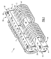
- the isolator includes a substantially cylindrical coil of wire rope 2 which has a predetermined number of individual consecutive coils.
- the isolator 1 also includes a pair of mounting blocks 3 and 4.
- Each of the mounting blocks has opposing top 3A and 4A, bottom 3B and 4B surfaces, opposing side surfaces 3C, 3D, 4C, 4C and opposing end surfaces 3E, 3F, 4E and 4F.
- the mounting bars are not limited to a rectangular shape, but may also be round, half-round, formed with a crescent or oval top surface, or formed with any other suitable geometry.
- Each mounting block 3 and 4 has a series of lateral hollow cylindrical members, channels and the like passing axially therethrough.
- the wire rope is manipulated through one hole of one mounting block into the opposing empty hole of the opposing mounting block in a continuous loop until a plurality of bights is formed. This result can also be achieved using a plurality of wire ropes.
- the process is continued until the wire rope is shaped into a helix.
- the helical formation imparts an elastic quality to the wire rope causing it to flex and contract in a spring-like manner when subject to a dynamic load. This in turn allows the mounting blocks to move vertically relative to one another dissipating energy in the process.
- Threaded fastener members 5A, 5B, 6A and 6B allow for either or both mounting blocks to be mounted on other objects.
- Series of dowel pins 7 and 8 are driven into each mounting block 3 and 4 at a location over each lateral hold so as to mechanically stake and/or engage the wire rope 2 into locking contact with each mounting block 3 and 4.
- the embodiment depicted in Fig. 1 illustrates a wire rope isolator 1 in which each lateral hole forged in each mounting block 3 and 4 has been staked by a series of dowel pins 7 and 8. In other embodiments, the staking of all lateral hole may not be required. As illustrated, the ends of the dowel pins not engaging the wire rope are pressed flush with the top surfaces 3A and 4A of the mounting blocks 3 and 4.
- the dowel pins used be constructed of a material that has a harder consistency than the mounting block and wire rope material.
- the mounting block and wire rope were forged from aluminum while the dowel pin was fashioned from hardened steel. This contrast eases the force necessary to drive the dowel pin through the mounting block and wire rope.
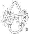
- Fig. 2 depicts a wire rope isolator 10 that does not manipulate the wire rope into a helix or coil.
- two mounting blocks 12 and 13 each with a pair of lateral holes 12A, 12B, 13A and 13B are spaced apart by a wire rope 11 that is passed through the lateral hole of one block into the empty lateral hole of the opposing block in an endless loop.
- the wire rope is manipulated into a geometric shape that allows the mounting blocks to move relative to each other due to the elasticity of the wire rope.
- a series of dowel pins 14 and 15 are driven through each mounting block 12 and 13 into the wire rope 11 contained therein.
- four dowel pins 14A, 14B, 14C, 14D, 15A, 15B, 15C and 15D are driven through the surface of the upper mounting block 12 into the lateral holes 12A and 12B containing the wire rope 11.
- the pins for the lower plate 13 are not shown. More or less dowel pins may be used to secure the wire rope in other embodiments.
- the dowel pins are pressed flush with the top surface of the mounting block and are composed of a material that is harder than the mounting block and wire rope material.
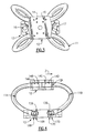
- Fig. 3 is a top view of Fig. 2 looking down on the isolator.
- Series of dowel pins 14 and 15 are driven through the outer surface of the upper mounting block into the lateral holes 12A and 12B (not shown) forged in the upper mounting block into the wire rope 11 contained therein to secure the upper mounting block 12 into locking contact with the wire rope 11.
- Threaded mounting holes 16 and 17 are shown in the bottom mounting block 13 so that isolator 10 can be affixed to the sensitive equipment intended to be protected.
- Fig. 4 is a cross sectional view along axis Z of the assembled isolator depicted Fig. 2.
- a wire rope 11 has been mechanically staked into locking contact with mounting blocks 12 and 13 by a plurality of dowel pins (14A, 14B, 14C and 14D secure the wire rope to the upper mounting block whereas dowels 16A, 16B, 17C and 17D secure the lower mounting block into locking contact).
- Wire rope 11 has been passed through the lateral holes 12A of the upper mounting block 12 and lateral holes 13A and 13B of the lower mounting block 13.
- the top mounting block 12 contains the terminal ends of wire rope 11 although several wire ropes can be utilized in other embodiments of the present invention.
- a thin vertical web may be situated in any of the vertical holes in which the wire rope is passed to create a "blind hole” to assist in locating the position of the ends of the wire rope 11 during the assembly of the isolator.
- Dowel pins 14A, 14B, 14C and 14D have been driven through the outer surface of the upper mounting block 12 into sections of the wire rope 11A and 11B contained there so as to engage the wire rope 11 into locking contact with upper mounting block 12. It should be noted that the dowel pins need not be driven into the mounting block from the top surface of the mounting block.
- the dowel pins could have been driven into the mounting block from the bottom or either opposing side surfaces as well, so long as the dowel pin is positioned over the lateral hole so that when a sufficient force is applied it is driven through the mounting block and into the wire rope contained therein.
- the dowel pins are pressed flush with the mounting plate surface during assembly.
- the wire rope 11 arcs outward from the mounting blocks creating bights having elastic qualities. During use, these bights flex and contract when subject to a dynamic load. In turn, the mounting blocks 12 and 13 move toward each dissipating energy in the process.
- the opposing ends of the wire are also secured by dowel pins 16A, 16B, 17C and 17D to the lower mounting block 13 in much the same manner.
- the wire rope is passed completely therethrough the lateral holes 13A and 13B contained in the lower mounting block 13.
- Fig. 5 is a cross-sectional view of a mounting block 12 containing a lateral hole 12A passing from one surface of the upper mounting block to the opposing surface of the upper mounting block.
- a wire rope 11 is passed through the lateral hole 12A of the mounting block 12.
- a dowel pin 14 has been driven through the outer surface of the mounting block 12 into the wire rope 11 contained in the lateral hole below the surface so as to said wire rope 11 into locking contact with the upper mounting block 12. As illustrated, in the preferred embodiment, the dowel pin 14 is pressed flush with the outer surface of the mounting block 12.
- Fig. 6 is a cross-sectional view of a mounting block 12 containing a lateral hole 12A passing from one surface of the upper mounting block to the opposing surface of the upper mounting block.
- a wire rope 11 is passed completely therethrough the lateral hole 12A of the mounting block 12.
- a dowel pin 14 having a tip shaped into a wedge has been driven through the outer surface of the mounting block 12 into the wire rope contained in the lateral hole situated below the outer surface so as to stake the wire rope 11 contained in the lateral hole 14 therein into locking contact with the mounting block 12.
- the dowel pin 14 stakes the wire rope 11 off-center so as to increase the area of contact between the dowel pin 14 and the wire rope 11.
- the dowel pin 14 is pressed flush with the outer surface of the mounting block 12.
- Fig. 7 is a cross-sectional view of a mounting block 12 containing a lateral hole 12A passing from one surface of the upper mounting block to the opposing surface of the mounting block 12.
- a wire rope 11 is passed completely therethrough the lateral hole 12A of the mounting block 12.
- a pilot hole 12C has been formed in the mounting block 12 perpendicularly to the lateral hole 12A in which the wire rope 11 is contained.
- the pilot hole 12C allows for the direct engagement of the dowel pin 14 with the wire rope 11.
- the dowel pin 14 need not be driven into the mounting block before staking the wire rope 11.
Landscapes
- Engineering & Computer Science (AREA)
- General Engineering & Computer Science (AREA)
- Mechanical Engineering (AREA)
- Vibration Prevention Devices (AREA)
- Springs (AREA)
- Vibration Dampers (AREA)
Abstract
A wire rope vibration isolator employing a wire cable (2) passed in a continuous loop
through lateral hollow, cylindrical members, holes, channels or the like, formed therethrough in
one or more mounting blocks or entrapment members. The mounting blocks manipulate the wire
cable into a geometric shape, such as a coil or helix, that is capable of imparting elastic, spring-like
qualities in the wire rope. The geometric shape of the wire rope is maintained and secured
by driving dowel pins of sufficient length through the outer surface of the mounting block into
the lateral hole contained therein to stake the wire rope into locking contact with the mounting
block. The dowel pins (14) are composed of material that has a harder consistency than the material
composing the mounting block and wire rope. The ends of the dowel pins not engaging the wire
rope are pressed flush to the top surface of the mounting block. Once assembled, the elastic
quality of the wire rope allows to flex and contract when exposed to vibrational energy. This
movement dissipates the unwanted vibrational energy. When attached to shock-sensitive
equipment, the isolator insulates the equipment from the damaging vibrational energy.
Description
- This invention relates in general to vibrational energy isolators, and in particular, wire rope isolators. More specifically, but without restriction to the particular embodiment hereinafter described in accordance with the best mode of practice, this invention relates to wire rope vibration isolators utilizing mounting blocks that employ dowel pins to mechanically engage wire ropes passed through lateral holes in the mounting blocks into locking contact with the blocks and the method of assembling such isolators.
- Many operations require energy absorption devices to divert damaging vibrational energy away from shock-sensitive equipment and machinery. Shipboard electronics and navigational equipment, pumps, generators and compressors, chemical processing equipment, avionics, process piping and various other industries utilize energy dampers to prevent damage and premature wear to equipment vital to daily operations. The most basic energy absorption devices employ simple internal machinery, like pistons and springs, to harmlessly consume vibrational or kinetic energy thereby insulating shock-sensitive equipment secured to the device from potential damage caused by the unwanted vibrational energy. For example, the common automotive shock absorber, a member of the class of these devices, uses the shock force caused by driving on an uneven surface to move an internal piston which in turn decreases the total amount of energy of the system.
- A common type of energy-absorbing restraint is the wire rope isolator. Most isolators of this class utilize a multi-strand wire rope that has been manipulated into a geometric shape. Particular geometric configurations impart the rope with elastic spring-like qualities which allow the wire rope to flex and contract when subject to dynamic displacement. The undulation of the rope consumes vibrational energy.
- Most wire rope isolators currently utilized in industrial applications shape the wire rope into a coil or helix, although other configurations, such as saddles, are possible. The desired geometry of the wire rope is attained, in most instances, by threading the wire rope through hollow cylindrical members, channels and the like drilled into two or more entrapment members or mounting blocks. To maintain the wire cable in a helical formation, some devices secure the two mounting blocks together with threaded fasteners. Examples of these types of isolators are illustrated in U.S. Patent No. 3,596,865 issued to C. Camossi, U.S. Patent No. 4,783,038 issued to C.L. Gilbert, et al., U.S. Patent No. 5,062,507 issued to A. Roche. In addition, the isolator designs illustrated in the Loziuk patents, U.S. Patent No. 5,441,243, U.S. Patent No. 5,522,585 and U.S. Patent No. 5,791,636, all of which suggest securing the two mounting blocks together with a threaded fastening means like a bolt which in turn maintains the helical formation of the wire rope. While this type of isolator has its advantages, there is a possibility that the threaded fasteners may become loose at some time.
- The vibration isolator proposed by R.E. Belfield et al., U.S. Patent No. 4,190,227 employs a method whereby the wire cable coil is molded in a retainer block which is formed from a thermoplastic material such as polyvinyl chloride or polystyrene. This proposal also has its disadvantages. It may fail under heavy loads or high temperatures. In addition, the bonded interface between the thermoplastic material and the wire cable may fail due to cyclic fatigue.
- The wire rope isolator illustrated in U.S. Patent No. 5,549,285 issued to Collins suggests that the wire rope configuration can be maintained and secured by a crimp. This type of isolator requires that the mounting blocks be forged from a malleable material. The wire rope cable is threaded through a series of lateral holes contained in the mounting blocks forming a helix. A force is then applied to at least one of the mounting blocks at a point where the wire rope is positioned so as to plastically deform the mounting block around the wire rope into locking contact. This design, however, is ill-suited for use with wire cables having large diameters. Wire ropes with large diameters require mounting blocks of substantial mass. Crimping a substantially thick mounting block around an equally dense wire cable would require a tremendous amount of force which in turn would result in an overall reduction of the integrity of the mounting block.
- The other wire rope isolators described herein that use fasteners to secure the wire rope in place are also ill-suited in applications using wire ropes with significant diameters. As such, the production of large-scale isolators is limited. Accordingly, there continues to be a need for wire rope isolators constructed with wire ropes having relatively great diameters assembled without the use of any mechanical fasteners.
- The present invention consists of a wire rope isolator that employs dowel pins to mechanically stake and/or engage the wire rope cable into locking contact with the mounting blocks. The dowel pins are forged of a material having a harder consistency than the material composing the mounting block and wire rope. The end of the dowel pin not engaging the wire rope is pressed flush to the outer surface of the mounting block. A simple wire rope isolator can be assembled by passing a wire cable through hollow cylindrical members, channels and the like contained in two or more mounting blocks so as to manipulate the wire rope into a geometric shape which imparts the wire rope with elastic, spring-like qualities. When the assembled isolator is connected to shock-sensitive machinery and/or equipment, the isolator insulates said machinery and/or equipment by deflecting potentially damaging vibrational energy away from the equipment when the mechanical system is subject to a dynamic load. In particular, the wire rope flexes and contracts causing the mounting blocks to move relative to each other to dissipate vibrational energy.
- In a preferred embodiment, the ends of the dowel pins engaging the wire cable can be a wedge so as to facilitate the staking process. This goal is also achieved by including pilot holes in the mounting blocks that are perpendicular to the lateral holes in which the wire rope is situated. The dowel pin is driven directly into the wire rope avoiding the need to penetrate the surface of the mounting block. In accordance with a further aspect of this invention, the dowel pins used can be forged from hard steel while the mounting block and isolator are made from aluminum.
- It is, therefore, an object of this present invention to improve energy absorption devices.
- Another object of this invention is to improve wire rope vibration isolators for use in industrial applications.
- It is a further object of the present invention to assemble a wire rope vibration isolator without the use of any mechanical fasteners.
- Still another object of the present invention is to assemble a wire rope isolator that uses a wire cable having a diameter greater than the diameter of conventional wire cables currently available in industrial applications without compromising the integrity of the mounting block in which the cable is housed.
- It is yet a further objective of the present invention to utilize all metal components in a wire rope vibration isolator so that the isolator may function under extreme operating conditions such as temperature and load.
- Yet still another object of the present invention is to avoid a bonded chemical interface between the block member and the wire rope.
- An additional object of the present invention to eliminate costly machining operations associated with securing retainer plates to the wire coils of a wire rope isolator.
- Yet a further object of the present invention is to reduce the number of parts required to assemble a wire rope isolator for industrial applications.
- Still yet another object of the present invention is to decrease the number of steps required for assembling a variety of sizes of wire rope isolators.
- These and other objectives are attained in accordance with the present invention.
- Further objects of the present invention together with additional features contributing thereto and advantages accruing therefrom will be apparent from the following description of a preferred embodiment of the invention which is shown in the accompanying drawings with like reference numerals indicating like components throughout, wherein:
- Fig.1 is a perspective view of one embodiment of a wire rope vibration isolator according to the present invention.
- Fig. 2 is a perspective view of another embodiment of a wire rope vibration isolator according to the present invention.
- Fig. 3 is a top view of the wire rope vibration isolator illustrated in Fig. 2.
- Fig. 4 is a cross-sectional view of a staked wire rope contained in the wire rope vibration isolator mounting block according to the present invention.
- Fig. 5 is a cross-sectional view of portion of a mounting block of one embodiment of the present invention after the wire rope has been passed through the lateral hole forged into the mounting block and a dowel pin has been driven into locking contact with said wire rope.
- Fig. 6 is a cross-sectional view of a select portion of a mounting block of one embodiment of the present invention in which head of the dowel pin is a wedge which is driven off-center into locking contact with the wire rope contained in a lateral hole of a mounting block.
- Fig. 7 is a cross-sectional view of a select portion of a mounting block of one embodiment of the present invention in which the mounting block is forged with pilot holes that are perpendicular to a lateral holes of the mounting block that contain a wire rope. Fig. 7 illustrates how the pilot hole facilitates the staking of the wire rope contained therein by allowing direct engagement of the wire rope by the dowel pin without first driving said dowel pin into the surface of the mounting block.
-
- Referring now to Fig. 1, there is shown a wire rope vibration isolator 1 in accordance with the present invention. The isolator includes a substantially cylindrical coil of
wire rope 2 which has a predetermined number of individual consecutive coils. The isolator 1 also includes a pair of mountingblocks block - Threaded
fastener members - Series of dowel pins 7 and 8 (not shown) are driven into each mounting
block wire rope 2 into locking contact with each mountingblock block top surfaces blocks - It is required that the dowel pins used be constructed of a material that has a harder consistency than the mounting block and wire rope material. In one embodiment of the present invention, the mounting block and wire rope were forged from aluminum while the dowel pin was fashioned from hardened steel. This contrast eases the force necessary to drive the dowel pin through the mounting block and wire rope.
- Fig. 2 depicts a
wire rope isolator 10 that does not manipulate the wire rope into a helix or coil. In this embodiment of the present invention, two mountingblocks lateral holes wire rope 11 that is passed through the lateral hole of one block into the empty lateral hole of the opposing block in an endless loop. As in the isolator depicted in Fig.1, the wire rope is manipulated into a geometric shape that allows the mounting blocks to move relative to each other due to the elasticity of the wire rope. - A series of dowel pins 14 and 15 (the dowel pins for the
lower mounting block 13 are not shown) are driven through each mountingblock wire rope 11 contained therein. In this particular embodiment, fourdowel pins upper mounting block 12 into thelateral holes wire rope 11. The pins for thelower plate 13 are not shown. More or less dowel pins may be used to secure the wire rope in other embodiments. Again, the dowel pins are pressed flush with the top surface of the mounting block and are composed of a material that is harder than the mounting block and wire rope material. - Fig. 3 is a top view of Fig. 2 looking down on the isolator. Series of dowel pins 14 and 15 are driven through the outer surface of the upper mounting block into the
lateral holes wire rope 11 contained therein to secure theupper mounting block 12 into locking contact with thewire rope 11. Threaded mountingholes bottom mounting block 13 so thatisolator 10 can be affixed to the sensitive equipment intended to be protected. - Fig. 4 is a cross sectional view along axis Z of the assembled isolator depicted Fig. 2. In this illustration, a
wire rope 11 has been mechanically staked into locking contact with mountingblocks dowels Wire rope 11 has been passed through thelateral holes 12A of theupper mounting block 12 andlateral holes lower mounting block 13. Thetop mounting block 12 contains the terminal ends ofwire rope 11 although several wire ropes can be utilized in other embodiments of the present invention. It is not required that the ends of thewire rope 11 abut as illustrated. In another embodiment of the present invention, a thin vertical web may be situated in any of the vertical holes in which the wire rope is passed to create a "blind hole" to assist in locating the position of the ends of thewire rope 11 during the assembly of the isolator. Dowel pins 14A, 14B, 14C and 14D have been driven through the outer surface of theupper mounting block 12 into sections of thewire rope wire rope 11 into locking contact withupper mounting block 12. It should be noted that the dowel pins need not be driven into the mounting block from the top surface of the mounting block. The dowel pins could have been driven into the mounting block from the bottom or either opposing side surfaces as well, so long as the dowel pin is positioned over the lateral hole so that when a sufficient force is applied it is driven through the mounting block and into the wire rope contained therein. In the preferred embodiment, the dowel pins are pressed flush with the mounting plate surface during assembly. - The
wire rope 11 arcs outward from the mounting blocks creating bights having elastic qualities. During use, these bights flex and contract when subject to a dynamic load. In turn, the mountingblocks - The opposing ends of the wire are also secured by
dowel pins lower mounting block 13 in much the same manner. In this perspective, the wire rope is passed completely therethrough thelateral holes lower mounting block 13. - Fig. 5 is a cross-sectional view of a mounting
block 12 containing alateral hole 12A passing from one surface of the upper mounting block to the opposing surface of the upper mounting block. Awire rope 11 is passed through thelateral hole 12A of the mountingblock 12. Adowel pin 14 has been driven through the outer surface of the mountingblock 12 into thewire rope 11 contained in the lateral hole below the surface so as to saidwire rope 11 into locking contact with theupper mounting block 12. As illustrated, in the preferred embodiment, thedowel pin 14 is pressed flush with the outer surface of the mountingblock 12. - Fig. 6 is a cross-sectional view of a mounting
block 12 containing alateral hole 12A passing from one surface of the upper mounting block to the opposing surface of the upper mounting block. Awire rope 11 is passed completely therethrough thelateral hole 12A of the mountingblock 12. Adowel pin 14 having a tip shaped into a wedge has been driven through the outer surface of the mountingblock 12 into the wire rope contained in the lateral hole situated below the outer surface so as to stake thewire rope 11 contained in thelateral hole 14 therein into locking contact with the mountingblock 12. In this embodiment, thedowel pin 14 stakes thewire rope 11 off-center so as to increase the area of contact between thedowel pin 14 and thewire rope 11. As illustrated, in the preferred embodiment, thedowel pin 14 is pressed flush with the outer surface of the mountingblock 12. - Fig. 7 is a cross-sectional view of a mounting
block 12 containing alateral hole 12A passing from one surface of the upper mounting block to the opposing surface of the mountingblock 12. Awire rope 11 is passed completely therethrough thelateral hole 12A of the mountingblock 12. In this embodiment of the present invention, apilot hole 12C has been formed in the mountingblock 12 perpendicularly to thelateral hole 12A in which thewire rope 11 is contained. Thepilot hole 12C allows for the direct engagement of thedowel pin 14 with thewire rope 11. In contrast to the other embodiments described herein, thedowel pin 14 need not be driven into the mounting block before staking thewire rope 11. - While this invention has been described in detail with reference to a certain preferred embodiment and a preferred method for making the illustrated embodiment, it should be appreciated that the present invention is not limited to those precise embodiments. Rather, in view of the present disclosure which describes the best mode for practicing the invention, many modifications and variations would present themselves to those of skill in the art without departing from the scope and spirit of this invention, as defined in the following claims.
Claims (14)
- A mounting block for a wire rope isolator that includes:a top and bottom surface, opposing side surfaces and two end surfaces;a series of lateral holes passing axially therethrough said side surfaces so that a wire rope can pass into and through said holes from one side surface to the other side surface; andat least one dowel pin composed of a material having a harder consistency than the material composing the mounting block, the dowel pin being driven into the mounting block so that one end of said dowel pin is flush to a surface of the mounting block and the opposing end of the dowel pin extends into a hole contained in said mounting block so that the dowel pin may mechanically engage, when a force of sufficient magnitude is applied to the dowel pin, a wire rope contained therein into locking contact with the mounting block without deforming the mounting block.
- The mounting block of claim 1 wherein said lateral holes are cylindrical.
- The mounting block of claim 1 wherein the end of said dowel pin engaging the wire rope is formed in the shape a wedge.
- The mounting block of claim 1 that further includes pilot holes perpendicular to the lateral holes contained in the mounting block so as to allow direct staking of a wire rope contained in said lateral hole without first driving said dowel pin into the mounting block.
- The mounting block of claims 1-4 wherein said dowel pin is composed of steel and said wire rope is composed of aluminum.
- A wire rope isolator that includes:a wire rope;a pair of opposed mounting blocks each mounting block further including a top and bottom surface, opposing side surfaces and two end surfaces and a series of lateral holes passing axially there through said side surfaces so that said wire rope can pass into and through said holes from one side surface to the other side surface and from one mounting block to the opposing mounting block; andat least one dowel pin composed of a material having a harder consistency than the material composing the mounting block, the dowel pin being driven into the mounting block so that one end of said dowel pin is flush to a surface of the mounting block and the opposing end extends into a hole contained in said mounting block so that the dowel pin mechanically engages, when a force of sufficient magnitude is applied to the dowel pin, the wire rope contained therein into locking contact with the mounting block without deforming the mounting block;whereby the mounting blocks move relative to each other to dissipate vibrational energy.
- The wire rope isolator of claim 6 wherein said lateral holes are cylindrical.
- The wire rope isolator of claim 6 that wherein the end of said dowel pin engaging the wire rope is formed in the shape a wedge.
- The wire rope isolator of claim 6 that further includes pilot holes perpendicular to the lateral holes contained in the mounting block so as to allow direct staking of a wire rope contained in said lateral hole without first driving said dowel pin into the mounting block.
- The wire rope isolator of claims 6-11 wherein said dowel pin is composed of steel and said wire rope is composed of aluminum.
- A method of constructing a wire rope isolator that includes the steps of:forming a mounting block having a top and bottom surface, opposing side surfaces and two end surfaces;passing holes axially through each of the mounting blocks;placing two mounting blocks in spaced apart alignment;passing a wire rope into and through the holes in said mounting blocks in an endless loop between the blocks;driving at least one dowel pin into a surface of each mounting block so that said dowel pin mechanically stakes the wire rope contained in the mounting block into locking contact with said mounting block;whereby the mounting blocks may move relative to each other to dissipate vibrational energy.
- The method of assembling the wire rope isolator of claim 11 wherein the end of said dowel pin engaging the wire rope is formed in the shape of a wedge.
- The method of assembling a wire rope isolator of claim 11 wherein said mounting block further contains pilot holes perpendicular to the lateral holes contained in the mounting block so as to allow direct staking of a wire rope contained in said lateral hole without first driving said dowel pin into the mounting block.
- The methods of assembling a wire rope isolator of claims 11-13 wherein said dowel pin is composed of steel and said wire rope is composed of aluminum.
Applications Claiming Priority (2)
| Application Number | Priority Date | Filing Date | Title |
|---|---|---|---|
| US09/496,517 US6406011B1 (en) | 2000-02-02 | 2000-02-02 | Wire rope isolator with pinned bar and method for making same |
| US496517 | 2000-02-02 |
Publications (1)
| Publication Number | Publication Date |
|---|---|
| EP1122458A1 true EP1122458A1 (en) | 2001-08-08 |
Family
ID=23972976
Family Applications (1)
| Application Number | Title | Priority Date | Filing Date |
|---|---|---|---|
| EP01101924A Withdrawn EP1122458A1 (en) | 2000-02-02 | 2001-01-28 | Wire rope isolator with pinned bar and method for making same |
Country Status (3)
| Country | Link |
|---|---|
| US (1) | US6406011B1 (en) |
| EP (1) | EP1122458A1 (en) |
| JP (1) | JP4366022B2 (en) |
Cited By (10)
| Publication number | Priority date | Publication date | Assignee | Title |
|---|---|---|---|---|
| WO2003019035A3 (en) * | 2001-08-08 | 2004-03-18 | Isic As | Vibration damper for dampening vibrations at low frequencies |
| EP1519073A1 (en) * | 2003-09-25 | 2005-03-30 | Sebert Schwingungstechnik GmbH | Damping arrangement comprising a cable loop arrangement as a damper |
| US7266451B2 (en) | 2004-03-11 | 2007-09-04 | Trimble Navigation Limited | Shock resistant device |
| DE102008008303B3 (en) * | 2008-02-07 | 2009-07-02 | Sebert Schwingungstechnik Gmbh | Damping and spring arrangement for damping and springing article, has two rope pieces whose end areas end radially to tube extension axis between partial pieces and are arranged around common axis of extension in distributed manner |
| EP2339202A1 (en) | 2009-12-24 | 2011-06-29 | Sebert Schwingungstechnik GmbH | Dampening and spring arrangement and method for its production |
| WO2013153173A1 (en) * | 2012-04-12 | 2013-10-17 | Sebert Schwingungstechnik Gmbh | Vibration isolator and method for the production thereof |
| CN104534004A (en) * | 2014-12-30 | 2015-04-22 | 柳州邦诚科技有限公司 | Spring-mass damping device |
| EP2955262A1 (en) * | 2014-06-10 | 2015-12-16 | Imesa Spa | Washing machine |
| US9255399B2 (en) | 2013-12-06 | 2016-02-09 | Itt Manufacturing Enterprises Llc | Seismic isolation assembly |
| US10539204B2 (en) | 2014-09-24 | 2020-01-21 | Itt Manufacturing Enterprises Llc | Damping and support device for electrical equipments |
Families Citing this family (57)
| Publication number | Priority date | Publication date | Assignee | Title |
|---|---|---|---|---|
| US6290217B1 (en) * | 2000-03-29 | 2001-09-18 | Enidine Incorporated | Asymmetric wire rope isolator |
| RU2305809C2 (en) * | 2003-10-13 | 2007-09-10 | Общество с ограниченной ответственностью "Научно-производственная фирма "АНКОМ" | Rope shock absorber and method of its making |
| US7325792B2 (en) * | 2005-03-11 | 2008-02-05 | Enidine, Inc. | Multi-axial base isolation system |
| TWI261095B (en) * | 2005-11-18 | 2006-09-01 | Ind Tech Res Inst | Steel wire vibration-isolator |
| US7581738B1 (en) * | 2006-02-06 | 2009-09-01 | Azimuth, Inc. | Moveable storage structure system |
| RU2322621C1 (en) * | 2006-08-10 | 2008-04-20 | Государственное образовательное учреждение высшего профессионального образования "Самарская государственная академия путей сообщения" (СамГАПС) | Method of production of rope elastic-hysteresis element |
| DE102008018094A1 (en) | 2008-04-09 | 2009-10-15 | Kolt Engineering Gmbh | Vibration damping arrangement e.g. for aeronautics electronics, and transport, |
| EP2382049A2 (en) | 2008-12-29 | 2011-11-02 | Otic Pharma Ltd. | Multiple-metered dispenser |
| US8640593B2 (en) | 2009-01-21 | 2014-02-04 | Rafael Advanced Defense Systems Ltd. | Damping suspension with an up-lift capability for an add-on armor system |
| KR20100111334A (en) * | 2009-04-07 | 2010-10-15 | 하동석 | Wire shock mount with motion guide and article having same |
| JP5281949B2 (en) * | 2009-04-21 | 2013-09-04 | 日本ゼニスパイプ株式会社 | Damper device and energy absorber |
| KR101126366B1 (en) * | 2009-04-23 | 2012-03-23 | 용석필 | Structure of fixing wire rope in wire rope isolator |
| JP5537856B2 (en) * | 2009-07-24 | 2014-07-02 | 株式会社田中制震構造研究所 | Vibration control device |
| US8657250B2 (en) | 2010-03-19 | 2014-02-25 | Winegard Company | Mount for a mobile satellite antenna system with vibration and shock isolation |
| GB201010419D0 (en) * | 2010-06-22 | 2010-08-04 | Secr Defence | Flexible bracket for vehicle armour |
| FR2975074B1 (en) * | 2011-05-11 | 2013-06-21 | Dcns | VESSEL TYPE HAVING AT LEAST ONE RECEPTION WELL OF AT LEAST ONE MISSILE LAUNCH CONTAINER |
| KR101261427B1 (en) | 2011-09-19 | 2013-05-10 | 주식회사 에이브이티 | The device of protecting vibration and wire mount for protecting vibration |
| KR101325131B1 (en) | 2011-10-27 | 2013-11-06 | 주식회사 수퍼센츄리 | A anti-vibration Mount |
| US9745840B2 (en) | 2012-11-16 | 2017-08-29 | Us Well Services Llc | Electric powered pump down |
| US11449018B2 (en) | 2012-11-16 | 2022-09-20 | U.S. Well Services, LLC | System and method for parallel power and blackout protection for electric powered hydraulic fracturing |
| US9893500B2 (en) | 2012-11-16 | 2018-02-13 | U.S. Well Services, LLC | Switchgear load sharing for oil field equipment |
| US10407990B2 (en) | 2012-11-16 | 2019-09-10 | U.S. Well Services, LLC | Slide out pump stand for hydraulic fracturing equipment |
| US10232332B2 (en) | 2012-11-16 | 2019-03-19 | U.S. Well Services, Inc. | Independent control of auger and hopper assembly in electric blender system |
| US11476781B2 (en) | 2012-11-16 | 2022-10-18 | U.S. Well Services, LLC | Wireline power supply during electric powered fracturing operations |
| US9995218B2 (en) | 2012-11-16 | 2018-06-12 | U.S. Well Services, LLC | Turbine chilling for oil field power generation |
| CA2908276C (en) | 2014-10-14 | 2022-11-01 | Us Well Services Llc | Parallel power and blackout protection for electric hydraulic fracturing |
| US10005506B2 (en) | 2015-02-27 | 2018-06-26 | Great Lakes Sound & Vibration, Inc. | Suspension arrangements for vehicles |
| US9788446B1 (en) * | 2015-03-27 | 2017-10-10 | Paul H. Townsend | Mobile vibration isolation device |
| US12078110B2 (en) | 2015-11-20 | 2024-09-03 | Us Well Services, Llc | System for gas compression on electric hydraulic fracturing fleets |
| JP6725287B2 (en) * | 2016-03-30 | 2020-07-15 | 不二ラテックス株式会社 | Anti-vibration device |
| US12027831B2 (en) | 2016-04-15 | 2024-07-02 | U.S. Well Services, LLC | Switchgear load sharing for oil field equipment |
| US10232936B2 (en) | 2016-11-22 | 2019-03-19 | Bell Helicopter Textron Inc. | Damper |
| US11326661B2 (en) | 2016-11-22 | 2022-05-10 | Textron Innovations Inc. | Damper |
| US11181107B2 (en) | 2016-12-02 | 2021-11-23 | U.S. Well Services, LLC | Constant voltage power distribution system for use with an electric hydraulic fracturing system |
| US10570984B1 (en) | 2017-06-28 | 2020-02-25 | United Launch Alliance, L.L.C. | Asymmetrically-shaped isolator |
| WO2019113153A1 (en) | 2017-12-05 | 2019-06-13 | U.S. Well Services, Inc. | High horsepower pumping configuration for an electric hydraulic fracturing system |
| WO2019113147A1 (en) | 2017-12-05 | 2019-06-13 | U.S. Well Services, Inc. | Multi-plunger pumps and associated drive systems |
| FR3075908B1 (en) * | 2017-12-27 | 2020-09-25 | Airbus Operations Sas | DAMPING SYSTEM INCLUDING A PRIMARY DAMPER AND A SECONDARY DAMPER DEVICE FOR DIFFERENT STIFFNESS, ASSOCIATED STRUCTURE AND AIRCRAFT |
| CA3103490A1 (en) | 2018-06-15 | 2019-12-19 | U.S. Well Services, LLC | Integrated mobile power unit for hydraulic fracturing |
| CN109183608A (en) * | 2018-09-12 | 2019-01-11 | 武汉东九永环工程技术有限公司 | A kind of wrapping wirerope, wrapping steel-wire rope damper and composite damping support |
| WO2020056258A1 (en) | 2018-09-14 | 2020-03-19 | U.S. Well Services, LLC | Riser assist for wellsites |
| US10914155B2 (en) | 2018-10-09 | 2021-02-09 | U.S. Well Services, LLC | Electric powered hydraulic fracturing pump system with single electric powered multi-plunger pump fracturing trailers, filtration units, and slide out platform |
| EP3705744B1 (en) | 2019-03-05 | 2021-10-20 | Bell Helicopter Textron Inc. | Damper |
| US11578577B2 (en) | 2019-03-20 | 2023-02-14 | U.S. Well Services, LLC | Oversized switchgear trailer for electric hydraulic fracturing |
| WO2020231483A1 (en) | 2019-05-13 | 2020-11-19 | U.S. Well Services, LLC | Encoderless vector control for vfd in hydraulic fracturing applications |
| AR119134A1 (en) | 2019-06-10 | 2021-11-24 | U S Well Services Llc | INTEGRATED COMBUSTION GAS HEATER FOR MOBILE FUEL CONDITIONING EQUIPMENT |
| US11459863B2 (en) | 2019-10-03 | 2022-10-04 | U.S. Well Services, LLC | Electric powered hydraulic fracturing pump system with single electric powered multi-plunger fracturing pump |
| CA3161918A1 (en) | 2019-12-27 | 2021-07-01 | Alexander CHRISTINZIO | Systems and methods for fluid end health monitoring |
| US11009162B1 (en) | 2019-12-27 | 2021-05-18 | U.S. Well Services, LLC | System and method for integrated flow supply line |
| US11885206B2 (en) | 2019-12-30 | 2024-01-30 | U.S. Well Services, LLC | Electric motor driven transportation mechanisms for fracturing blenders |
| US11492886B2 (en) | 2019-12-31 | 2022-11-08 | U.S. Wells Services, LLC | Self-regulating FRAC pump suction stabilizer/dampener |
| US20210219446A1 (en) * | 2020-01-15 | 2021-07-15 | Dell Products L.P. | Vibration damping and shock isolation in transportation tote |
| US11582874B2 (en) | 2020-01-15 | 2023-02-14 | Dell Products L.P. | Interlocking transportation totes |
| US20230185344A1 (en) * | 2021-12-09 | 2023-06-15 | Evga Corporation | Computer case structure suspended and fixed by steel cables |
| CN115789157B (en) * | 2022-11-04 | 2025-09-16 | 中国科学院长春光学精密机械与物理研究所 | Wire rope vibration isolator and installation method thereof |
| CN118408001B (en) * | 2024-07-01 | 2024-09-24 | 成都世源频控技术股份有限公司 | Vibration reduction structure, manufacturing method and crystal oscillator with vibration reduction structure |
| CN119460391B (en) * | 2024-11-25 | 2026-03-20 | 中国航天三江集团有限公司 | Optical equipment shipping packaging boxes |
Citations (5)
| Publication number | Priority date | Publication date | Assignee | Title |
|---|---|---|---|---|
| SU1395867A1 (en) * | 1986-11-10 | 1988-05-15 | Куйбышевский авиационный институт им.акад.С.П.Королева | Vibration isolator |
| US4783038A (en) * | 1987-07-07 | 1988-11-08 | Aeroflex International Incorporated | Isolator apparatus |
| US5062507A (en) * | 1988-09-05 | 1991-11-05 | Vibrachoc | Vibration and shock absorber device |
| WO1994004843A1 (en) * | 1992-08-20 | 1994-03-03 | Carlo Camossi | Elastic anti-impact and anti-vibration metal cable device for supporting a rotary unit |
| US5549285A (en) * | 1995-04-21 | 1996-08-27 | Enidine, Inc. | Wire rope isolator with crimp bar and method for making same |
Family Cites Families (9)
| Publication number | Priority date | Publication date | Assignee | Title |
|---|---|---|---|---|
| US3596865A (en) | 1967-05-26 | 1971-08-03 | Carlo Camossi | Metal cable absorber mounting system |
| US4190227A (en) | 1976-07-22 | 1980-02-26 | Aeroflex Laboratories, Inc. | Vibration isolator and method for manufacturing same |
| NZ208129A (en) * | 1984-05-11 | 1988-10-28 | New Zealand Dev Finance | Shear energy absorber: confined granular material within deformable block |
| US5240232A (en) | 1991-12-16 | 1993-08-31 | Abb Impell Corporation | Pipe restraint |
| US5441243A (en) * | 1992-07-16 | 1995-08-15 | Vectra Technologies, Inc. | Wire cable isolator and energy absorbing restraint |
| US5791636A (en) | 1992-07-16 | 1998-08-11 | Loziuk; Larry | Compact profile wire cable isolator and energy absorbing restraint |
| FR2738888B1 (en) * | 1995-09-20 | 1998-12-04 | Socitec | ANTI-VIBRATION/ANTI-SHOCK DEVICE OF THE KIND COMPRISING A BEARING ELEMENT AND A CARRY ELEMENT UNITED BY CABLE SEGMENTS AND STABILIZING BLADES |
| US5791635A (en) * | 1997-01-13 | 1998-08-11 | Hull; Harold L. | Fence post with anchor |
| KR200179733Y1 (en) * | 1997-11-15 | 2000-05-01 | 최동환 | Device for correcting twist of wire rope isolator |
-
2000
- 2000-02-02 US US09/496,517 patent/US6406011B1/en not_active Expired - Lifetime
-
2001
- 2001-01-28 EP EP01101924A patent/EP1122458A1/en not_active Withdrawn
- 2001-02-02 JP JP2001027541A patent/JP4366022B2/en not_active Expired - Lifetime
Patent Citations (5)
| Publication number | Priority date | Publication date | Assignee | Title |
|---|---|---|---|---|
| SU1395867A1 (en) * | 1986-11-10 | 1988-05-15 | Куйбышевский авиационный институт им.акад.С.П.Королева | Vibration isolator |
| US4783038A (en) * | 1987-07-07 | 1988-11-08 | Aeroflex International Incorporated | Isolator apparatus |
| US5062507A (en) * | 1988-09-05 | 1991-11-05 | Vibrachoc | Vibration and shock absorber device |
| WO1994004843A1 (en) * | 1992-08-20 | 1994-03-03 | Carlo Camossi | Elastic anti-impact and anti-vibration metal cable device for supporting a rotary unit |
| US5549285A (en) * | 1995-04-21 | 1996-08-27 | Enidine, Inc. | Wire rope isolator with crimp bar and method for making same |
Non-Patent Citations (1)
| Title |
|---|
| SOVIET PATENTS ABSTRACTS Section PQ Week 198847, Derwent World Patents Index; Class Q63, AN 1988-336690, XP002167904 * |
Cited By (15)
| Publication number | Priority date | Publication date | Assignee | Title |
|---|---|---|---|---|
| WO2003019035A3 (en) * | 2001-08-08 | 2004-03-18 | Isic As | Vibration damper for dampening vibrations at low frequencies |
| US7234153B2 (en) | 2001-08-08 | 2007-06-19 | Isic A/S | Vibration damper for dampening vibrations at low frequencies |
| EP1519073A1 (en) * | 2003-09-25 | 2005-03-30 | Sebert Schwingungstechnik GmbH | Damping arrangement comprising a cable loop arrangement as a damper |
| US7303185B2 (en) | 2003-09-25 | 2007-12-04 | Sebert Schwingungstechnik Gmbh | Damping arrangement with a cable loop arrangement serving as a damping member |
| US7266451B2 (en) | 2004-03-11 | 2007-09-04 | Trimble Navigation Limited | Shock resistant device |
| WO2005088338A3 (en) * | 2004-03-11 | 2009-02-26 | Trimble Navigation Ltd | Shock resistant device |
| DE102008008303B3 (en) * | 2008-02-07 | 2009-07-02 | Sebert Schwingungstechnik Gmbh | Damping and spring arrangement for damping and springing article, has two rope pieces whose end areas end radially to tube extension axis between partial pieces and are arranged around common axis of extension in distributed manner |
| EP2339202A1 (en) | 2009-12-24 | 2011-06-29 | Sebert Schwingungstechnik GmbH | Dampening and spring arrangement and method for its production |
| WO2013153173A1 (en) * | 2012-04-12 | 2013-10-17 | Sebert Schwingungstechnik Gmbh | Vibration isolator and method for the production thereof |
| US9255399B2 (en) | 2013-12-06 | 2016-02-09 | Itt Manufacturing Enterprises Llc | Seismic isolation assembly |
| US9809975B2 (en) | 2013-12-06 | 2017-11-07 | Itt Manufacturing Enterprises Llc | Seismic isolation assembly |
| EP2955262A1 (en) * | 2014-06-10 | 2015-12-16 | Imesa Spa | Washing machine |
| US10539204B2 (en) | 2014-09-24 | 2020-01-21 | Itt Manufacturing Enterprises Llc | Damping and support device for electrical equipments |
| CN104534004A (en) * | 2014-12-30 | 2015-04-22 | 柳州邦诚科技有限公司 | Spring-mass damping device |
| CN104534004B (en) * | 2014-12-30 | 2017-02-22 | 柳州邦诚科技有限公司 | spring-mass damping device |
Also Published As
| Publication number | Publication date |
|---|---|
| JP2001241477A (en) | 2001-09-07 |
| JP4366022B2 (en) | 2009-11-18 |
| US6406011B1 (en) | 2002-06-18 |
Similar Documents
| Publication | Publication Date | Title |
|---|---|---|
| US6406011B1 (en) | Wire rope isolator with pinned bar and method for making same | |
| EP1666760B1 (en) | Asymmetric wire rope isolator | |
| US5549285A (en) | Wire rope isolator with crimp bar and method for making same | |
| JP3848366B2 (en) | Locking tool with snake-shaped gripping member | |
| US6244579B1 (en) | Light press manufactured (LPM) wire rope isolator and method of manufacture | |
| CA1329330C (en) | Differential thread for transfer of screw thread force | |
| EP0499518B1 (en) | Isolator with improved symmetrical response to shock and vibration forces | |
| US20100003074A1 (en) | Connecting structure of steel bar | |
| NZ737520A (en) | A resilient slip friction joint | |
| DE112013005260T5 (en) | Device for vibration damping | |
| EP0350927B1 (en) | Composite bar structures of interlocked multiple members and method of producing the same | |
| CA2438136C (en) | A splicing for interconnected thin-walled metal structures | |
| WO2014166849A2 (en) | Aseismic connection device for connecting a panel to a beam | |
| US6299150B1 (en) | Composite spring mount shock absorber | |
| RU2390668C1 (en) | Cylinder rope damper | |
| JP4383963B2 (en) | Bolt break type buffer stopper device and bridge seismic isolation device | |
| GB2317432A (en) | Coil spring | |
| EP2162589A1 (en) | Damping device and fastening arrangment | |
| KR20160122956A (en) | Multiaction-type Plate Steel Damper | |
| KR101362927B1 (en) | Wire rope isolator and vibration isolation system using the same | |
| US20030165370A1 (en) | Method and structure for locknut with substantially rigid locking member | |
| KR102108429B1 (en) | Anti-loosing nut equipped with locking pin and production method therof | |
| JPH0564367U (en) | Stress limiting mechanism of truss shaft structural material | |
| EP0762012B1 (en) | Dynamic damper | |
| US6966736B2 (en) | Method and structure for locking nut with deformable member |
Legal Events
| Date | Code | Title | Description |
|---|---|---|---|
| PUAI | Public reference made under article 153(3) epc to a published international application that has entered the european phase |
Free format text: ORIGINAL CODE: 0009012 |
|
| AK | Designated contracting states |
Kind code of ref document: A1 Designated state(s): DE FR IT |
|
| AX | Request for extension of the european patent |
Free format text: AL;LT;LV;MK;RO;SI |
|
| AKX | Designation fees paid |
Free format text: DE FR IT |
|
| STAA | Information on the status of an ep patent application or granted ep patent |
Free format text: STATUS: THE APPLICATION IS DEEMED TO BE WITHDRAWN |
|
| 18D | Application deemed to be withdrawn |
Effective date: 20020209 |