EP1122472B1 - Dichtsystem zwischen einer Welle und einem feststehenden Gehäuseteil - Google Patents
Dichtsystem zwischen einer Welle und einem feststehenden Gehäuseteil Download PDFInfo
- Publication number
- EP1122472B1 EP1122472B1 EP01102224A EP01102224A EP1122472B1 EP 1122472 B1 EP1122472 B1 EP 1122472B1 EP 01102224 A EP01102224 A EP 01102224A EP 01102224 A EP01102224 A EP 01102224A EP 1122472 B1 EP1122472 B1 EP 1122472B1
- Authority
- EP
- European Patent Office
- Prior art keywords
- shaft
- ring
- inner ring
- sealing
- wall
- Prior art date
- Legal status (The legal status is an assumption and is not a legal conclusion. Google has not performed a legal analysis and makes no representation as to the accuracy of the status listed.)
- Expired - Lifetime
Links
Images

Classifications
-
- F—MECHANICAL ENGINEERING; LIGHTING; HEATING; WEAPONS; BLASTING
- F16—ENGINEERING ELEMENTS AND UNITS; GENERAL MEASURES FOR PRODUCING AND MAINTAINING EFFECTIVE FUNCTIONING OF MACHINES OR INSTALLATIONS; THERMAL INSULATION IN GENERAL
- F16J—PISTONS; CYLINDERS; SEALINGS
- F16J15/00—Sealings
- F16J15/16—Sealings between relatively-moving surfaces
- F16J15/32—Sealings between relatively-moving surfaces with elastic sealings, e.g. O-rings
- F16J15/3248—Sealings between relatively-moving surfaces with elastic sealings, e.g. O-rings provided with casings or supports
- F16J15/3252—Sealings between relatively-moving surfaces with elastic sealings, e.g. O-rings provided with casings or supports with rigid casings or supports
- F16J15/3256—Sealings between relatively-moving surfaces with elastic sealings, e.g. O-rings provided with casings or supports with rigid casings or supports comprising two casing or support elements, one attached to each surface, e.g. cartridge or cassette seals
-
- F—MECHANICAL ENGINEERING; LIGHTING; HEATING; WEAPONS; BLASTING
- F16—ENGINEERING ELEMENTS AND UNITS; GENERAL MEASURES FOR PRODUCING AND MAINTAINING EFFECTIVE FUNCTIONING OF MACHINES OR INSTALLATIONS; THERMAL INSULATION IN GENERAL
- F16J—PISTONS; CYLINDERS; SEALINGS
- F16J15/00—Sealings
- F16J15/16—Sealings between relatively-moving surfaces
- F16J15/164—Sealings between relatively-moving surfaces the sealing action depending on movements; pressure difference, temperature or presence of leaking fluid
Definitions
- the invention relates to a sealing system of the kind referred to in the preamble of claim 1 in more detail.
- the fixed outer ring which limits the liquid space to the outside substantially, seen with its annular gap bounding wall in the radial direction relative to the other hand, the annular gap delimiting wall of the inner ring outwardly disposed.
- a Wellenabdichtsystem other genus is known from the utility model DE-U1-71 41 842. There it is to a standstill seal with an expanding at higher shaft speeds under the centrifugal force, elastic sealing ring which seals a space with higher gas pressure from a space with lower gas pressure at shaft standstill against gas transfer.
- a recirculating seal is provided, which is effective with open standstill seal and consists for example of a Wegringstopfbüchse or a labyrinth seal.
- the arrangement of the annular gap in the region of the stationary seal can in principle be arbitrary and different than shown in the cited document, for example cylindrical.
- the new shaft sealing system is intended primarily for use in geared motors consisting of a drive module and a gear module.
- a drive module and a gear module are combined to form a complete drive from a series and modular system.
- the drive modules assume the function of sealing the entire drive from the environment on the input side.
- the seal between the rotating shaft of the drive module and its stationary housing is made by radial shaft seals. Between the rotating shaft and the fixed sealing lip of the radial shaft sealing rings creates a relative movement, which leads to wear and thus to a limited life of the seal. The life of such seals is smaller with increasing speed and with increasing shaft diameter.
- the invention is therefore based on the idea of using a shaft sealing system for the latter application as well, which corresponds to the generic features and operates wear-free above a limiting rotational speed of the shaft.
- the invention is therefore an object of the invention to provide a sealing system of the type mentioned above, which allows under all operating conditions from standstill on the start up to the rated speed of the shaft as good as complete seal against the space to be kept free of the relevant medium.
- the pressure of the creeping or flowable medium due to the acting centrifugal force in the region of the annular gap radially outwards against the rotating wall of the inner ring and thereby the rotation of the medium is not slowed down. Consequently, even in the radially outer mouth region of the annular gap, a centrifugal force acts on the medium, whereby a secure return of the medium in the sealed space is achieved.
- FIG. 1 a shaft 1, which is guided through a housing part 2.
- a shaft seal which consists of an inner ring 3, a sealing lip 4 arranged thereon and an outer ring 5 and which has further details, which will be discussed below with reference to FIG.
- a sealed space A On the left in Figure 1 side of the shaft seal is a sealed space A, in which a creeping or flowable medium is included. It is in the space A primarily to the interior of a transmission of a geared motor in which the flowable medium consists of lubricating oil.
- a space B On the right in Figure 1 side adjoins the shaft seal a space B, which is to be kept clear of the medium contained in the space A, this space is in the case of a geared motor to the interior of the drive motor.
- the inner ring 3 adjoins the inner space A to be sealed, and the outer ring 5 of the shaft seal adjoins the space to be kept clear.
- the inner ring 3 is rotatably connected to the shaft 1, while the outer ring 5 is arranged on the fixed housing part 2 and thus also is stationary.
- annular interior 11 Between the inner ring 3 and the outer ring 5 is a largely enclosed, annular interior 11, in which a U-shaped holder 12 is used for the sealing lip 4, wherein the sealing lip 4 is disposed on a flange of this U-shaped holder 12, the at Rotation can escape radially under centrifugal force outward.
- the sealing lip 4 is engaged in the radial direction inwardly by a collar 6 of the outer ring 5.
- the sealing lip 4 rests on the outer circumference of this collar 6 and stands out from it at higher speeds under the action of Fliekrafteinrial with appropriate deformation of the holder 12 from.
- the inner ring 3, the sealing lip 4 and the holder 12 may be made in one piece, this can be made of a suitable plastic, the wall thickness is tuned in the region of the holder 12 and the sealing lip 4 on the Beweglichtkeit.
- annular space 8 To the sealing lip 4 closes to the shaft 1 toward an annular space 8, which is connected via a gap-shaped annular space 10 with the space B to be kept free.
- annular space 7 In the direction away from the shaft 1, the inner space 11 adjoins the sealing lip 4, and an annular gap 7, which is in communication with the sealed space A, adjoins this inner space 11.
- the annular gap 7 extends inclined relative to the axis of the shaft 7 as well to the radial direction, thus it has both an axial and a radial direction component. Limited the annular gap 7 is formed by a first wall 14, which is formed on the inner side of an edge part 13 of the inner ring 3. By projecting away from the shaft 1 on the inner ring 3 protruding edge portion 13 of the entire inner ring 3 is replaced by a bowl shape, wherein the hollow part of the inner ring 3 surrounds a correspondingly raised part of the outer ring 5.
- the outer ring 5 has a wall 15 which is parallel to the wall 14. Both walls 14 and 15 have straight generatrices, whereby the walls 14 and 15 are conical. Basically, the walls 14 and 15 may also be curved or curved, for example, parabolic, it is only crucial that especially at the wall 14 at the edge portion 13 of the inner ring 3 at any point such a slope relative to the axis of the shaft 1 is present that at Rotation of the inner ring 3 together with the shaft 1, the medium located in the annular gap 7 under the action of the centrifugal force in the direction of the shaft 1 away up to an overflowing into the space A mouth 9 of the annular gap 7 is conveyed. It is important that seen in the radial direction with the shaft 1 rotating wall 14 of the inner ring 3 is exposed to the outside.
Landscapes
- Engineering & Computer Science (AREA)
- General Engineering & Computer Science (AREA)
- Mechanical Engineering (AREA)
- Sealing With Elastic Sealing Lips (AREA)
- Sealing Using Fluids, Sealing Without Contact, And Removal Of Oil (AREA)
- Sealing Of Bearings (AREA)
Description
- Die Erfindung bezieht sich auf ein Dichtsystem der im Gattungsbegriff des Patentanspruchs 1 näher bezeichneten Art.
- Derartige Dichtsysteme sind aus den Offenlegungsschriften US-A-4 277 072, EP 0 117 267 A1 und DE 35 35 445 A1 bekannt. Vornehmlich werden die bekannten Systeme in Kurbelwellengehäusen von Brennkraftmaschinen verwendet, wobei es darum geht, ein Gas-Flüssigkeits-Gemisch und ein Luft-Öl-Gemisch voneinander abzudichten. Zwar kommt es auch hierbei darauf an, eine Flüssigkeitsrückförderung zum abgedichteten Flüssigkeitsraum hin zu erzielen, eine vollständige Abdichtung des Flüssigkeitsraums wird mit den bekannten Systemen jedoch nicht erreicht.
- Denn bei den bekannten Systemen ist der feststehende Außenring, welcher im wesentlichen den Flüssigkeitsraum nach außen hin begrenzt, mit seiner den Ringspalt begrenzenden Wandung in radialer Richtung gesehen gegenüber der andererseits den Ringspalt begrenzenden Wandung des Innenrings nach außen hin liegend angeordnet. Dadurch wird unter der Fliehkrafteinwirkung das in den abgedichteten Raum zurückzubefördernde Medium gegen eine stillstehende Wandung gedrückt, und es verliert dadurch an Geschwindigkeit in Rotatonsrichtung, wodurch die Fliehkrafteinwirkung sich verringert.
- Ein Wellenabdichtsystem anderer Gattung ist aus dem Gebrauchsmuster DE-U1-71 41 842 bekannt. Dort handelt es sich um eine Stillstandsdichtung mit einen sich bei höheren Wellendrehzahlen unter der Fliehkrafteinwirkung aufweitenden, elastischen Dichtring, der einen Raum mit höherem Gasdruck von einem Raum mit niedrigerem Gasdruck bei Wellenstillstand gegen einen Gasübertritt abdichtet. Zusätzlich zu dieser Stillstandsdichtung ist eine Umlaufdichtung vorgesehen, welche bei offener Stillstandsdichtung wirksam ist und beispielsweise aus einer Schwimmringstopfbüchse oder einer Labyrinthdichtung besteht. Die Anordnung des Ringspaltes im Bereich der Stillstandsdichtung kann grundsätzlich beliebig und anders als in dem zitierten Dokument dargestellt, z.B. zylindrisch sein.
- Das neue Wellenabdichtsystem ist vornehmlich für den Einsatz bei Getriebemotoren vorgesehen, die aus einem Antriebsmodul und aus einem Getriebemodul bestehen. Um unterschiedlichen Anforderungen zu entsprechen, werden aus einem Baureihen- und Baukastensystem jeweils ein Antriebsmodul und ein Getriebemodul zu einem Gesamtantrieb kombiniert. Die Antriebsmodule übernehmen neben der Einleitung von Drehmoment und Drehzahl die Funktion der eingangsseitigen Abdichtung des Gesamtantriebs gegenüber der Umgebung. Bei allen bekannten Baukastensystemen dieser Art wird die Abdichtung zwischen der umlaufenden Welle des Antriebsmoduls und dessem feststehendem Gehäuse durch Radialwellendichtringe vorgenommen. Zwischen der umlaufenden Welle und der feststehenden Dichtlippe der Radialwellendichtringe entsteht eine Relativbewegung, die zu Verschleiß und damit zu einer zeitlich begrenzten Lebensdauer der Dichtung führt. Die Lebensdauer solcher Dichtungen wird mit wachsender Drehzahl und mit wachsendem Wellendurchmesser kleiner.
- Die Erfindung geht deshalb von der Überlegung aus, auch für den letzteren Einsatzfall ein Wellenabdichtsystem zu verwenden, welches den Gattungsmerkmalen entspricht und oberhalb einer Grenzdrehzahl der Welle verschleißfrei arbeitet.
- Deshalb liegt der Erfindung die Aufgabe zugrunde, ein Dichtsystem der eingangs genannten Art zu schaffen, welches unter allen Betriebszuständen vom Stillstand über den Anlauf bis zur Nenndrehzahl der Welle hin eine so gut wie vollständige Abdichtung gegenüber dem von dem betreffenden Medium freizuhaltenden Raum ermöglicht.
- Diese Aufgabe wird bei dem Dichtsystem der gattungsgemäßen Art durch die kennzeichnenden Merkmale des Patentanspruchs 1 gelöst.
- Für die Erfindung ist wesentlich, daß bei rotierendem System der Andruck des kriech- oder fließfähigen Mediums infolge der einwirkenden Zentrifugalkraft im Bereich des Ringspaltes radial nach außen gegen die rotierende Wandung des Innenringes erfolgt und dadurch die Rotationsmitnahme des Mediums nicht gebremst wird. Folglich wirkt selbst im radial äußeren Mündungsbereich des Ringspaltes noch eine Zentrifugalkraft auf das Medium, womit eine sichere Rückförderung des Mediums in den abgedichteten Raum erzielt wird.
- Vorteilhafte Ausgestaltungsmerkmale der Erfindung ergeben sich aus den Unteransprüchen.
- Die Erfindung wird nachfolgend anhand der Zeichnung an einem Ausführungsbeispiel noch näher erläutert. Dabei zeigen:
- Fig. 1
- einen Axialschnitt durch ein zwischen einer Welle und einem Gehäuseteil angeordnetes Wellenabdichtsystem und
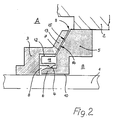
- Fig. 2
- die in Figur 1 eingekreiste Einzelheit "X" in vergrößerter Wiedergabe.
- Im einzelnen erkennt man in Figur 1 eine Welle 1, die durch ein Gehäuseteil 2 hindurchgeführt ist. Im Bereich der Wellendurchführung befindet sich eine Wellenabdichtung, die aus einem Innenring 3, einer daran angeordneten Dichtlippe 4 und aus einem Außenring 5 besteht und die weitere Einzelheiten aufweist, welche nachstehend anhand von Figur 2 erörtert werden.
- Auf der in Figur 1 linken Seite der Wellendichtung befindet sich ein abzudichtender Raum A, in welchem ein kriech- oder fließfähiges Medium enthalten ist. Es handelt sich bei dem Raum A vornehmlich um den Innenraum eines Getriebes eines Getriebemotors, bei dem das fließfähige Medium aus Schmieröl besteht. Auf der in Figur 1 rechten Seite grenzt an die Wellendichtung ein Raum B an, der von dem im Raum A enthaltenen Medium freizuhalten ist, bei diesem Raum handelt es sich im Fall eines Getriebemotors um den Innenraum des Antriebsmotors. An den abzudichtenden, inneren Raum A grenzt der Innenring 3 und an den freizuhaltenden Raum grenzt der Außenring 5 der Wellendichtung an.
- Wie Figur 2 deutlicher erkennen läßt, ist der Innenring 3 drehfest mit der Welle 1 verbunden, während der Außenring 5 an dem feststehenden Gehäuseteil 2 angeordnet ist und somit ebenfalls feststehend ist. Zwischen dem Innenring 3 und dem Außenring 5 besteht ein weitgehend umschlossener, ringförmiger Innenraum 11, in den ein U-förmiger Halter 12 für die Dichtlippe 4 eingesetzt ist, wobei die Dichtlippe 4 an einem Flansch dieses U-förmigen Halters 12 angeordnet ist, der bei Rotation unter Fliehkrafteinwirkung radial nach au-ßen hin ausweichen kann. Die Dichtlippe 4 wird in radialer Richtung nach innen hin von einem Kragen 6 des Außenringes 5 untergriffen. Bei Stillstand und bei niedrigen Drehzahlen der Welle 1 liegt die Dichtlippe 4 auf dem Außenumfang dieses Kragens 6 auf und hebt sich davon bei höheren Drehzahlen unter der Fliekrafteinwirkung bei entsprechender Verformung des Halters 12 ab. Der Innenring 3, die Dichtlippe 4 und der Halter 12 können einstückig ausgeführt sein, dazu kann auf einen geeigneten Kunststoff zurückgegriffen werden, dessen Wandungsstärke im Bereich des Halters 12 und der Dichtlippe 4 auf deren Beweglichtkeit abgestimmt ist.
- An die Dichtlippe 4 schließt zur Welle 1 hin ein Ringraum 8 an, der über einen spaltförmigen Ringraum 10 mit dem freizuhaltenden Raum B in Verbindung steht. In Richtung von der Welle 1 weg grenzt der Innenraum 11 an die Dichtlippe 4 an und an diesen Innenraum 11 schließt ein Ringspalt 7 an, der mit dem abgedichteten Raum A in Verbindung steht.
- Der Ringspalt 7 verläuft geneigt relativ zur Achse der Welle 7 ebenso zur Radialrichtung, er hat somit sowohl eine axiale als auch eine radiale Richtungskomponente. Begrenzt wird der Ringspalt 7 von einer ersten Wandung 14, die an der Innenseite eines Randteils 13 des Innenringes 3 gebildet ist. Durch das von der Welle 1 weg geneigt am Innenring 3 abstehende Randteil 13 erhält der gesamte Innenring 3 eine Schüsselform, wobei der hohle Teil des Innenringes 3 einen entsprechend erhaben ausgeformten Teil des Außenringes 5 umgibt.
- Gegenüber der Wandung 14 des Randteils 13 des Innenringes 3 hat der Außenring 5 eine Wandung 15, die mit der Wandung 14 parallel ist. Beide Wandungen 14 und 15 haben gerade verlaufende Mantellinien, womit die Wandungen 14 und 15 konisch ausgebildet sind. Grundsätzlich können die Wandungen 14 und 15 auch gekrümmt oder gewölbt sein, beispielsweise parabolisch, entscheidend ist lediglich, daß vor allem bei der Wandung 14 am Randteil 13 des Innenringes 3 an jeder Stelle eine solche Neigung relativ zur Achse der Welle 1 vorhanden ist, daß bei Rotation des Innenringes 3 zusammen mit der Welle 1 das im Ringspalt 7 befindliche Medium unter Einwirkung der Zentrifugalkraft in Richtung von der Welle 1 weg bis zu einer in den Raum A übegehenden Mündung 9 des Ringspaltes 7 befördert wird. Wichtig ist, daß in radialer Richtung gesehen die mit der Welle 1 rotierende Wandung 14 des Innenringes 3 nach außen hinliegt.
- Bei Rotation der Welle 1 zusammen mit dem Innenring 3 wird auf das Medium im Raum A, das im Stillstand bis zu der auf den Kragen 6 des Außenringes 5 aufliegenden Dichtlippe 4 vordringen kann, von der Drehbewegung mitgenommen und ebenfalls in Rotation versetzt. Die hierdurch radial auf das
- Medium wirkende Zentrifugalkraft treibt das Medium aus dem Raum 11 durch den Ringspalt 7 hindurch in den Raum A. Hierbei wird das Medium ständig von der rotierenden Wandung 14 des Randteils 13 des Innenringes 3 mitgenommen, wodurch bis hin zur der Mündung 9 des Ringspaltes 7 eine umso größere Zentrifugalkraft auf das Medium wirkt, die mit dem radialen Abstand von der Welle 1 zunimmt. Somit kann oberhalb einer Grenzdrehzahl eine vollkommene dynamische Abdichtung des Raums A gegenüber dem Raum B erzielt werden, wenngleich ab dieser Grenzdrehzahl die Dichtlippe 4, die mit dem Innenring 3 rotiert, von dem Kragen 6 des Außenringes 5 abgehoben ist.
Claims (6)
- Dichtsystem zwischen einer Welle (1) und einem umgebenden, feststehenden Gehäuseteil (2), in welchem ein ein kriech- oder fließfähiges Medium enthaltender, abgedichteter Raum (A) sowie ein von dem Medium freizuhaltender Raum (B) in Achsrichtung der Welle (1) aneinander angrenzen, bestehend aus einem mit der Welle (1) drehfesten Innenring (3) mit einer sich unter der Fliehkraftwirkung bei rotierender Welle radial aufweitenden, elastischen Dichtlippe (4), die in radialer Richtung zur Welle (1) hin von einem mit ihr koaxialen Kragen (6) eines am Gehäuseteil (2) festen Außenringes (5) untergriffen ist und die den Kragen (6) bei Wellenstillstand sowie bei geringen Drehzahlen berührt, und ferner mit einem in Richtung von der Welle (1) weg an die Dichtlippe (4) anschließenden Ringspalt (7) zwischen dem Innenring (3) und dem Außenring (5), der in den abgedichteten Raum (A) mündet, und mit einem nach innen zur Welle (1) hin an die Dichtlippe (6) anschließenden Ringraum (8), der mit dem freizuhaltenden Raum (B) in Verbindung steht,
dadurch gekennzeichnet,
daß der an die Dichtlippe (4) anschließende Ringspalt (7) zumindest entlang eines Abschnittes zwischen einer Wandung (14) des Innenringes (3) und einer Wandung (15) des Außenringes (5) verläuft, die beide je eine Neigung relativ zur Wellenachse bzw. zur Radialrichtung mit einer entsprechenden Radial- sowie einer Axialkomponente haben, wobei die Wandung (14) des Innenringes (3) in radialer Richtung nach außen hin liegend die Wandung (15) des Außenringes (5) umgibt. - Dichtsystem nach Anspruch 1,
dadurch gekennzeichnet,
daß die Wandungen (14, 15) des Innenringes (3) und des Außenringes (5) im Bereich des Ringspaltes (7) miteinander parallel sind. - Dichtsystem nach Anspruch 1 oder 2,
dadurch gekennzeichnet,
daß zumindest eine der Wandungen (14, 15) des Innenringes (3) und des Außenringes (5) im Bereich des Ringspaltes (7) konisch ist. - Dichtsystem nach einem der Ansprüche 1 bis 3,
dadurch gekennzeichnet,
daß der Innenring (3) die Form einer Schüssel hat und einen geneigten Randabschnitt (13) aufweist, dessen Innenseite die den Ringspalt (8) begrenzende Wandung (14) bildet, welche einem geneigten Stirnseitenabschnitt des Außenringes (5), der die Wandung (15) bildet, gegenüberliegt. - Dichtsystem nach einem der Ansprüche 1 bis 4,
dadurch gekennzeichnet,
daß derInnenring (3) und die Dichtlippe (4) mit einem diese tragenden Halter (12) eine bauliche Einheit bilden. - Dichtsystem nach Anspruch 5,
dadurch gekennzeichnet,
daß der Innenring (3), die Dichtlippe (4) und deren Halter (12) einstückig sind.
Applications Claiming Priority (2)
| Application Number | Priority Date | Filing Date | Title |
|---|---|---|---|
| DE10004265 | 2000-02-01 | ||
| DE10004265A DE10004265A1 (de) | 2000-02-01 | 2000-02-01 | Dichtsystem zwischen einer Welle und einem feststehenden Gehäuseteil |
Publications (3)
| Publication Number | Publication Date |
|---|---|
| EP1122472A2 EP1122472A2 (de) | 2001-08-08 |
| EP1122472A3 EP1122472A3 (de) | 2005-01-05 |
| EP1122472B1 true EP1122472B1 (de) | 2006-04-26 |
Family
ID=7629400
Family Applications (1)
| Application Number | Title | Priority Date | Filing Date |
|---|---|---|---|
| EP01102224A Expired - Lifetime EP1122472B1 (de) | 2000-02-01 | 2001-01-31 | Dichtsystem zwischen einer Welle und einem feststehenden Gehäuseteil |
Country Status (2)
| Country | Link |
|---|---|
| EP (1) | EP1122472B1 (de) |
| DE (2) | DE10004265A1 (de) |
Cited By (6)
| Publication number | Priority date | Publication date | Assignee | Title |
|---|---|---|---|---|
| EP2182256A1 (de) | 2008-10-30 | 2010-05-05 | Lenze Drives GmbH | Wellenabdichtung an einer Wellendurchführung |
| EP2182257A1 (de) | 2008-10-30 | 2010-05-05 | Lenze Drives GmbH | Dichtungsanordnung zwischen einer Welle und einem Gehäuseteil |
| EP2497977A1 (de) | 2011-03-09 | 2012-09-12 | Lenze Drives GmbH | Wellendichtungssystem |
| US11231110B2 (en) | 2018-09-10 | 2022-01-25 | BRUSS Sealing Systems GmbH | Shaft seal having a shaft sealing ring |
| CN114483606A (zh) * | 2020-11-11 | 2022-05-13 | 中国石油化工股份有限公司 | 一种离心压缩机 |
| DE102021203468A1 (de) | 2021-04-08 | 2022-10-13 | Lenze Se | Wellendichtsystem |
Families Citing this family (6)
| Publication number | Priority date | Publication date | Assignee | Title |
|---|---|---|---|---|
| GB0317055D0 (en) | 2003-07-22 | 2003-08-27 | Cross Mfg Co 1938 Ltd | Improvements relating to aspirating face seals and thrust bearings |
| GB2459503A (en) * | 2008-04-25 | 2009-10-28 | Pioneer Weston Internat Ltd | Seal assembly comprising inner and outer rings which are rotatable relative to each other and each having annular sealing means |
| US11309764B2 (en) | 2012-06-26 | 2022-04-19 | DePuy Synthes Products, Inc. | Systems and apparatus for providing motor protection in a power tool and method of manufacturing the same |
| US10617431B2 (en) * | 2012-06-26 | 2020-04-14 | DePuy Synthes Products, Inc. | Systems and apparatus for providing motor protection in a power tool and method of manufacturing the same |
| DE102022002580A1 (de) * | 2022-07-14 | 2024-01-25 | C&U Europe Holding GmbH | Dichtungsvorrichtung für eine Lageranordnung und Lageranordnung mit der Dichtungsvorrichtung |
| WO2024104734A1 (de) * | 2022-11-17 | 2024-05-23 | Sew-Eurodrive Gmbh & Co. Kg | Dichtanordnung mit flanschteil und drehbar gelagerter welle |
Family Cites Families (6)
| Publication number | Priority date | Publication date | Assignee | Title |
|---|---|---|---|---|
| DE7141842U (de) * | 1971-11-05 | 1972-01-27 | Bbc Gmbh | Dichtungsanordnung |
| EP0012133B1 (de) * | 1978-12-15 | 1981-09-30 | Firma Carl Freudenberg | Dichtung für den Spalt zwischen einer umlaufenden Welle und einer Gehäusebohrung gegenüber einem Gemisch aus einer Flüssigkeit und einem Gas |
| DE3365527D1 (en) * | 1983-02-26 | 1986-10-02 | Freudenberg Carl Fa | Seal ring |
| DE3535445A1 (de) | 1985-10-04 | 1987-04-16 | Goetze Ag | Wellenabdichtungssystem |
| JPS62228760A (ja) * | 1986-03-31 | 1987-10-07 | Toyo Electric Mfg Co Ltd | 軸封装置 |
| FI79563C (fi) * | 1988-03-21 | 1990-01-10 | Sunds Defibrator Jylha Oy | Taetning foer passagen foer en roterande axel vid en raffinoer som framstaeller mekanisk massa av lignocellulosahaltigt material. |
-
2000
- 2000-02-01 DE DE10004265A patent/DE10004265A1/de not_active Ceased
-
2001
- 2001-01-31 DE DE50109577T patent/DE50109577D1/de not_active Expired - Lifetime
- 2001-01-31 EP EP01102224A patent/EP1122472B1/de not_active Expired - Lifetime
Cited By (10)
| Publication number | Priority date | Publication date | Assignee | Title |
|---|---|---|---|---|
| EP2182256A1 (de) | 2008-10-30 | 2010-05-05 | Lenze Drives GmbH | Wellenabdichtung an einer Wellendurchführung |
| EP2182257A1 (de) | 2008-10-30 | 2010-05-05 | Lenze Drives GmbH | Dichtungsanordnung zwischen einer Welle und einem Gehäuseteil |
| DE102008054045A1 (de) | 2008-10-30 | 2010-05-06 | Lenze Drives Gmbh | Dichtungsanordnung zwischen einer Welle und einem Gehäuseteil |
| DE102008054046A1 (de) | 2008-10-30 | 2010-05-06 | Lenze Drives Gmbh | Wellenabdichtung an einer Wellendurchführung |
| EP2497977A1 (de) | 2011-03-09 | 2012-09-12 | Lenze Drives GmbH | Wellendichtungssystem |
| DE102011005308A1 (de) | 2011-03-09 | 2012-09-13 | Lenze Drives Gmbh | Wellendichtungssystem |
| US11231110B2 (en) | 2018-09-10 | 2022-01-25 | BRUSS Sealing Systems GmbH | Shaft seal having a shaft sealing ring |
| CN114483606A (zh) * | 2020-11-11 | 2022-05-13 | 中国石油化工股份有限公司 | 一种离心压缩机 |
| CN114483606B (zh) * | 2020-11-11 | 2024-03-26 | 中国石油化工股份有限公司 | 一种离心压缩机 |
| DE102021203468A1 (de) | 2021-04-08 | 2022-10-13 | Lenze Se | Wellendichtsystem |
Also Published As
| Publication number | Publication date |
|---|---|
| DE10004265A1 (de) | 2001-08-09 |
| EP1122472A2 (de) | 2001-08-08 |
| DE50109577D1 (de) | 2006-06-01 |
| EP1122472A3 (de) | 2005-01-05 |
Similar Documents
| Publication | Publication Date | Title |
|---|---|---|
| EP3456945B1 (de) | Getriebe mit einem ölverteilungssystem | |
| DE2839233C2 (de) | ||
| EP1122472B1 (de) | Dichtsystem zwischen einer Welle und einem feststehenden Gehäuseteil | |
| EP1261820B1 (de) | Labyrinthdichtung zwischen drehbaren bauteilen | |
| EP2047143B1 (de) | Pumpenantrieb eines automatgetriebes | |
| DE112014004707B4 (de) | Leistungsübertragungsvorrichtung | |
| EP2192272A1 (de) | Vorrichtung zum Abdichten eines Lagergehäuses eines Abgasturboladers | |
| EP1487587B1 (de) | Separator mit hydrohermetischer abdichtung der spindel | |
| DE1936492A1 (de) | Rotationsmaschine | |
| DE3238780C1 (de) | Ölschmiersystem für Getriebe | |
| DE69838677T2 (de) | Dichtvorrichtung für eine zentrifuge | |
| WO1999054051A1 (de) | Freistrahlzentrifuge | |
| DE2538577C2 (de) | Anordnung zur Dämpfung von Biegeschwingungen des Rotors von Maschinen mit einer Freiträgerwelle | |
| DE102020101847A1 (de) | Exzentrisch oszillierender Drehzahlminderer | |
| DE4200687A1 (de) | Radiallager | |
| DE102020124608A1 (de) | Dichtvorrichtung mit dynamischer Dichtwirkung, insbesondere für Wälzlager | |
| DE3338417C1 (de) | Planetenraeder-Hilfsgetriebe fuer ein Kraftfahrzeug | |
| DE1425955B2 (de) | Axiallager | |
| DE4332465B4 (de) | Zweimassenschwungrad | |
| DE4409021A1 (de) | Berührungsfrei laufende, gasgeschmierte Gleitringdichtung | |
| DE19639451A1 (de) | Schmierstruktur für eine Übertragungseinrichtung | |
| DE4123392A1 (de) | Wellendichtring | |
| DE19928450C2 (de) | Labyrinthdichtung | |
| DE102020105798A1 (de) | Bremsvorrichtung | |
| DE4306141A1 (de) | Verstelleinrichtung für Propellerpumpen |
Legal Events
| Date | Code | Title | Description |
|---|---|---|---|
| PUAI | Public reference made under article 153(3) epc to a published international application that has entered the european phase |
Free format text: ORIGINAL CODE: 0009012 |
|
| AK | Designated contracting states |
Kind code of ref document: A2 Designated state(s): AT BE CH CY DE DK ES FI FR GB GR IE IT LI LU MC NL PT SE TR |
|
| AX | Request for extension of the european patent |
Free format text: AL;LT;LV;MK;RO;SI |
|
| RAP1 | Party data changed (applicant data changed or rights of an application transferred) |
Owner name: LENZE DRIVE SYSTEMS GMBH |
|
| PUAL | Search report despatched |
Free format text: ORIGINAL CODE: 0009013 |
|
| AK | Designated contracting states |
Kind code of ref document: A3 Designated state(s): AT BE CH CY DE DK ES FI FR GB GR IE IT LI LU MC NL PT SE TR |
|
| AX | Request for extension of the european patent |
Extension state: AL LT LV MK RO SI |
|
| GRAP | Despatch of communication of intention to grant a patent |
Free format text: ORIGINAL CODE: EPIDOSNIGR1 |
|
| 17P | Request for examination filed |
Effective date: 20050524 |
|
| AKX | Designation fees paid |
Designated state(s): DE FR GB IT |
|
| GRAS | Grant fee paid |
Free format text: ORIGINAL CODE: EPIDOSNIGR3 |
|
| GRAA | (expected) grant |
Free format text: ORIGINAL CODE: 0009210 |
|
| AK | Designated contracting states |
Kind code of ref document: B1 Designated state(s): DE FR GB IT |
|
| PG25 | Lapsed in a contracting state [announced via postgrant information from national office to epo] |
Ref country code: IT Free format text: LAPSE BECAUSE OF FAILURE TO SUBMIT A TRANSLATION OF THE DESCRIPTION OR TO PAY THE FEE WITHIN THE PRESCRIBED TIME-LIMIT;WARNING: LAPSES OF ITALIAN PATENTS WITH EFFECTIVE DATE BEFORE 2007 MAY HAVE OCCURRED AT ANY TIME BEFORE 2007. THE CORRECT EFFECTIVE DATE MAY BE DIFFERENT FROM THE ONE RECORDED. Effective date: 20060426 |
|
| REG | Reference to a national code |
Ref country code: GB Ref legal event code: FG4D Free format text: NOT ENGLISH |
|
| GBT | Gb: translation of ep patent filed (gb section 77(6)(a)/1977) |
Effective date: 20060426 |
|
| REF | Corresponds to: |
Ref document number: 50109577 Country of ref document: DE Date of ref document: 20060601 Kind code of ref document: P |
|
| ET | Fr: translation filed | ||
| PLBE | No opposition filed within time limit |
Free format text: ORIGINAL CODE: 0009261 |
|
| STAA | Information on the status of an ep patent application or granted ep patent |
Free format text: STATUS: NO OPPOSITION FILED WITHIN TIME LIMIT |
|
| 26N | No opposition filed |
Effective date: 20070129 |
|
| PGFP | Annual fee paid to national office [announced via postgrant information from national office to epo] |
Ref country code: IT Payment date: 20120124 Year of fee payment: 12 |
|
| PGFP | Annual fee paid to national office [announced via postgrant information from national office to epo] |
Ref country code: GB Payment date: 20121120 Year of fee payment: 13 |
|
| PGFP | Annual fee paid to national office [announced via postgrant information from national office to epo] |
Ref country code: FR Payment date: 20130129 Year of fee payment: 13 |
|
| GBPC | Gb: european patent ceased through non-payment of renewal fee |
Effective date: 20140131 |
|
| REG | Reference to a national code |
Ref country code: FR Ref legal event code: ST Effective date: 20140930 |
|
| PG25 | Lapsed in a contracting state [announced via postgrant information from national office to epo] |
Ref country code: FR Free format text: LAPSE BECAUSE OF NON-PAYMENT OF DUE FEES Effective date: 20140131 Ref country code: GB Free format text: LAPSE BECAUSE OF NON-PAYMENT OF DUE FEES Effective date: 20140131 |
|
| PG25 | Lapsed in a contracting state [announced via postgrant information from national office to epo] |
Ref country code: IT Free format text: LAPSE BECAUSE OF NON-PAYMENT OF DUE FEES Effective date: 20140131 |
|
| PGFP | Annual fee paid to national office [announced via postgrant information from national office to epo] |
Ref country code: DE Payment date: 20191221 Year of fee payment: 20 |
|
| REG | Reference to a national code |
Ref country code: DE Ref legal event code: R071 Ref document number: 50109577 Country of ref document: DE |