EP1125693A1 - Parallelkinematisches System - Google Patents
Parallelkinematisches System Download PDFInfo
- Publication number
- EP1125693A1 EP1125693A1 EP00102940A EP00102940A EP1125693A1 EP 1125693 A1 EP1125693 A1 EP 1125693A1 EP 00102940 A EP00102940 A EP 00102940A EP 00102940 A EP00102940 A EP 00102940A EP 1125693 A1 EP1125693 A1 EP 1125693A1
- Authority
- EP
- European Patent Office
- Prior art keywords
- control device
- kinematic system
- end effector
- actuators
- parallel kinematic
- Prior art date
- Legal status (The legal status is an assumption and is not a legal conclusion. Google has not performed a legal analysis and makes no representation as to the accuracy of the status listed.)
- Withdrawn
Links
Images

Classifications
-
- B—PERFORMING OPERATIONS; TRANSPORTING
- B25—HAND TOOLS; PORTABLE POWER-DRIVEN TOOLS; MANIPULATORS
- B25J—MANIPULATORS; CHAMBERS PROVIDED WITH MANIPULATION DEVICES
- B25J9/00—Program-controlled manipulators
- B25J9/16—Program controls
- B25J9/1615—Program controls characterised by special kind of manipulator, e.g. planar, scara, gantry, cantilever, space, closed chain, passive/active joints and tendon driven manipulators
- B25J9/1623—Parallel manipulator, Stewart platform, links are attached to a common base and to a common platform, plate which is moved parallel to the base
-
- B—PERFORMING OPERATIONS; TRANSPORTING
- B25—HAND TOOLS; PORTABLE POWER-DRIVEN TOOLS; MANIPULATORS
- B25J—MANIPULATORS; CHAMBERS PROVIDED WITH MANIPULATION DEVICES
- B25J17/00—Joints
- B25J17/02—Wrist joints
- B25J17/0258—Two-dimensional joints
- B25J17/0266—Two-dimensional joints comprising more than two actuating or connecting rods
-
- G—PHYSICS
- G05—CONTROLLING; REGULATING
- G05B—CONTROL OR REGULATING SYSTEMS IN GENERAL; FUNCTIONAL ELEMENTS OF SUCH SYSTEMS; MONITORING OR TESTING ARRANGEMENTS FOR SUCH SYSTEMS OR ELEMENTS
- G05B2219/00—Program-control systems
- G05B2219/30—Nc systems
- G05B2219/41—Servomotor, servo controller till figures
- G05B2219/41309—Hydraulic or pneumatic drive
-
- G—PHYSICS
- G05—CONTROLLING; REGULATING
- G05B—CONTROL OR REGULATING SYSTEMS IN GENERAL; FUNCTIONAL ELEMENTS OF SUCH SYSTEMS; MONITORING OR TESTING ARRANGEMENTS FOR SUCH SYSTEMS OR ELEMENTS
- G05B2219/00—Program-control systems
- G05B2219/30—Nc systems
- G05B2219/50—Machine tool, machine tool null till machine tool work handling
- G05B2219/50162—Stewart platform, hexapod construction
Definitions
- the invention relates to a parallel kinematic system positioning at least two actuators in parallel kinematics act on an end effector device and each with this by connecting means in at least two degrees of freedom of movement are articulated and in which the actuators one through a stator along a longitudinal axis of movement have guided runners.
- the invention further relates to a method for operating a parallel kinematic system of the type mentioned above as well a control device and a program module for each parallel kinematic system of the type mentioned above.
- the object is further achieved by a method according to the Technical teaching of claim 17, a control device according to the technical teaching of claim 19 and a program module according to the technical teaching of claim 20.
- the invention is based on the idea of a parallel kinematic System with fluid technology, especially with pneumatic drives.
- the runners of these drives not only between the respective end positions in the stators leading them be operated in the so-called "point-to-point” mode, but take any intermediate positions, so point a so-called path following behavior.
- This is what drives everyone Adjusting means, in particular at least one proportional valve assigned, via which the fluid power drive effect on the respective runner, especially the Effect of compressed air continuously, i.e. continuously, adjustable is.
- the actuating means are controlled by a control device, e.g. a microprocessor control, depending that of detection means, e.g.
- the control device expediently controls the adjusting means in such a way that the end effector device, when required Positioning runs through a defined trajectory, the end effector device in intermediate positions runs over a predetermined time sequence. So that can ensure that the end effector device is not with any objects in their work area collided.
- control device advantageously monitors the actuators in that the end effector device as much as possible, but not overly accelerated or is slowed down, for example if one with liquid filled vessel through the end effector device is transported. Furthermore, the control device can also the respective travel speed of the end effector device control and control.
- the Stators or housings of the components carrying the actuators the device frame of the parallel kinematic system, so that in itself necessary for the construction of a frame Frame components can be omitted and a special one light and inexpensive construction arises.
- control device is modular constructed and has, for example, a central control module as well as decentralized, assigned to the respective drives, so-called axis controller modules.
- the axis controller modules then set positions predetermined by the central control module of the respective runner and correct if necessary Deviations of the actual position values from by Central control module predetermined position target values.
- the control device it is also possible for the control device to be the central one Control device is formed and one of the control device software used in the above Way is modular.
- control device in particular the central control module, to what extent non-linear forces, especially gravitational forces, Centrifugal forces, Coriolis forces and coupling forces, act on and control the end effector device Adjusting means, if necessary compensating for these non-linear forces, on.
- the compensation control module controls the adjusting means for the compensation of the non-linear forces either directly to or expediently indirectly via the axis controller modules, which are then used accordingly have provided "compensation force input".
- Figure 1 shows three pneumatic linear drives as actuators 10, 11 and 12, which are arranged columnar with vertical orientation and are between a substantially star-shaped Base plate 8 and the same as the base plate 8 designed cover plate 9 extend in such a way that between the longitudinal axes of the linear drives 10, 11 and 12 a work space, preferably in the form of a regular one Prisms on the base of an isosceles triangle is spanned.
- the longitudinal axes of the linear drives show 10, 11 and 12 each at one end perpendicular to the corner points of the isosceles spanned on the base plate 8 Triangle and other ends on the corner points of the on the Cover plate 9 stretched isosceles triangle.
- a hexagonal work table 7 is arranged on the base plate 8. In this way, a device frame 6 of the parallel kinematic Systems defined.
- the cover plate 9 is omitted or is closer together Has corner points as the base plate 8 and the linear drives 10, 11 and 12 then a pyramidal or truncated pyramid Open the work area.
- the linear drives 10, 11 and 12 can also be used as required be arranged differently or inclined than in Figure 1.
- Die Linear drives 10, 11 and 12 can for example also in parallel be arranged side by side.
- the cover plate 9 can e.g. also hung on a ceiling surface or side wall surface be and the base plate 8 omitted.
- the first linear drive 10 has a rotor 14a which is guided by a stator 15a.
- the second linear drive 11 is a rotor 14b in a stator 15b in which third linear drive 12 a rotor 14c in a rotor 15c guided.
- the runners 14a, 14b and 14c is an end effector device 13 connected, the following only as "End effector 13" is called.
- End effector 13 is for example a gripper, a drill or as in the present In case a pneumatic suction device is attached, the is moved by positioning the runners 14a, 14b and 14c.
- linear drives 10, 11 and 12 each basically are constructed in the same way, in the following only the first linear drive 10 explained in more detail, the components of each Reference characters are provided, which consist of a number and an the number appended "a".
- Each of the components of the linear drive 10 corresponding components of the second Linear drives 11 are with the same numbers, but with one added "b", corresponding components of the third Linear actuator 12 designated with an attached "c".
- the stator 14a essentially comprises one as an elongated one Hollow body designed profile rod 16a, the axial Longitudinal direction at one end on the base plate 8 completed with the help of angle brackets foot 17a and is held at the other end by one with the Cover plate 9 connected head piece 18a is completed. Other shapes would also be for these end elements possible. Furthermore, the angle brackets can also be omitted, if the foot 17a, for example with the base plate 8 of the Bottom is screwed here.
- the profile bar 16a has in the present case a square cross-section on the outside on. In the interior of the profile bar 16a extends in Longitudinal direction over a cavity not visible in Figure 1 the entire length of the profile bar 16a.
- the rotor 14a is designed as a carriage with a e.g. L-shaped Profile executed, one leg of the profile with the Driver is connected and the other leg of the profile bar 16a encompasses.
- the runner 14a is by a reason the clarity, not shown, on the profile bar 16a arranged longitudinal guide guided safely and precisely.
- the first linear actuator 10 also referred to as "rodless linear drive”.
- rodless linear drive In principle, it can be of a type known per se.
- piston rods in particular also conventional pneumatic cylinders. Mixed forms too both drive types in a parallel kinematic Systems are easily possible.
- the rotor 14a from the piston instead of by mechanical driving action can also be moved, for example, by magnetic action, so that the slots 19a, 19b, 19c are not necessary.
- the rotor 14a is via parallel connecting rods 20a and 21a connected to the end effector 13.
- the connecting rods In the present case, 20a and 21a consist of special lightweight, yet resilient and torsion-resistant carbon fiber material.
- ball joints 23a, 24a, 25a and 26a are arranged, with which the connecting rods 20a and 21a one end with the Runner 14a and the other end connected to the end effector 13 are.
- the parallel connecting rods 20a and 21a as well as the Ball joints 23a, 24a, 25a and 26a form connecting means, with which the runner 14a in at least two degrees of freedom of movement is articulated to the end effector 13.
- ball joints for example, universal joints can also be used or other joint arrangements with at least two Degrees of freedom of movement are used.
- the runners 14b and 14c are similar to the runner 14a by parallel connecting rods 20b and 21b or 20c and 21c and corresponding by the ball joints 23a, 24a, 25a and 26a Ball joints 23b-26b and 23c-26c each with the end effector 13 connected.
- the connecting rods 20c and 21c are however in Figure 1 in part by the connecting rods 20b and 21b and the second linear drive 11 are covered. Through the The use of parallel connecting rods is described here If a rotary movement of the end effector 13 is suppressed, a translational movement with three degrees of freedom however enables.
- the stators form the linear drives 10, 11 and 12, in particular their profile bars 16a, 16b, 16c already supporting frame components of the parallel kinematic Systems, so that hardly any further frame components are necessary are.
- the base plate 8 and the cover plate 9 can are even completely eliminated if the linear drives 10, 11 and 12 via the head pieces 18a, 18b, 18c directly with each other are connected.
- valve assembly 27 Two compressed air connections each lead from a valve arrangement 27 28a, 28b and 28c at the feet 17a, 17b and 17c the linear drives 10, 11 and 12.
- the valve assembly 27 is connected via a line 29 from a Compressed air source, not shown, supplied with compressed air.
- the valve assembly 27 includes for each of the linear actuators 10, 11 and 12 adjusting means, the fluidic drive effect continuously on the respective rotor of a linear drive influence. Compressed air doses both on the side of the head pieces 18a, 18b and 18c also on the side of the feet 17a, 17b and 17c, that is to say both Sides of the respective piston, into the profile bars 16a, 16b and 16c can be fed. Furthermore, this means the profile bars 16a, 16b and 16c on both sides Head pieces 18a, 18b and 18c as well as on the side of the feet 17a, 17b and 17c are vented in a controlled manner.
- Adjustment means for each linear drive with at least one and preferably two proportional valves, each with functionality of a 3/3 valve, so that the pressure on the side of the respective head piece and on the side of the respective Foot can be individually adjusted. It is also possible, for example, that instead of two each Proportional valves functioning as 3/3 valves a valve with the functionality of a 5/3 proportional valve is provided.
- the adjusting means each have individually adjustable funding or that, for example, compressed air is only supplied via the feet is, then the pistons of the linear drives either by mechanical springs, by so-called air springs or be reset by gravity.
- the valve assembly 27 can also be constructed in a decentralized manner, with the respective to an actuator belonging to a linear drive also in the linear drive can be integrated.
- the linear drives 10, 11 and 12 are each in FIG. 1 Invisible position detection means for recording the Positions of the runners 14a, 14b and 14c arranged.
- the position detection means are inside the stators 15a, 15b and 15c arranged sensors, for example by radar or ultrasound the position of the respective runner 14a, 14b and 14c.
- the path measurement by the position detection means can also e.g. on magnetostrictive or inductive way, in particular in this If necessary, the sensors along the profile bars 16a, 16b and 16c can be attached.
- Signaling lines 30a lead from the position detection means, 30b and 30c to a merely shown schematically Control device 40 that performs the functions of parallel kinematic Systems controls.
- the control device 40 has a Input / output module 41, a processor 42 and storage means 43, each with connections not shown to each other are connected.
- the control device 40 is operated by an operating system and operated by software modules that are stored in the storage means 43 and their program code sequences executed by processor 42.
- RAM Random Access Memory
- ROM Read Only Memory
- From the tax facility 40 leads a control line 44 to the valve arrangement 27 to control them and thus to influence them the linear drives 10, 11 and 12.
- Via a signal line 45 the valve arrangement 27 of the control device 40 can be current Report statuses and settings.
- the control device 40 detects the respective of the position detection means via the message lines 30a, 30b and 30c to the control device 40 reported positions of Runner 14a, 14b and 14c and sends depending on the respective Positions control commands on the control line 44 the valve arrangement 27.
- the linear drives are then used for this 10, 11 and 12 either via feet 17a, 17b and 17c or via the head pieces 18a, 18b and 18c Compressed air or vented that the rotor 14a, 14b and 14c move in the profile bars 16a, 16b and 16c and a position desired by the control device 40 take in.
- About the runners 14a, 14b and 14c the end effector 13 according to the specifications of the control device 40 moves.
- the control device 40 is for the runners 14a, 14b and 14c not just their respective, for a particular positioning of the end effector 13 necessary end position, but also controls the movement of the runners 14a, 14b and 14c between these end positions so that the end effector 13 passes through a predetermined trajectory. In this way is avoided that the end effector 13 during a positioning process with possibly on the work table 7 Objects collided.
- the control device also provides 40 by appropriate activation of the valve arrangement 27 for this, that the end effector 13 accelerates as quickly as possible or is braked, but acceleration values are too high be avoided.
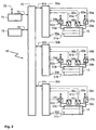
- the control device 40 is in the embodiment in Figure 2 is modular, wherein the modules as individual software modules within a central one Control device 40 can be formed or as decentralized control modules, for example on a common Bus work. Such decentralized control modules can also in whole or in part as analog electrical circuits be constructed or each have a processor, memory, Have input / output modules and control software. Mixed forms are also possible.
- Figure 2 shows the linear drives 10, 11 and 12, for simplification the representation in the design already mentioned above designed as a working cylinder with pistons and piston rods are.
- first linear drive 10 Components with a reference number consisting of a number and a "a” provided components assigned to the second linear drive 11 accordingly with a digit and "b" and the third Components assigned to linear drive 12 correspondingly with a Number and "c" designated.
- FIG. 2 only those assigned to the first linear drive 10 Components explained.
- the first linear drive 10 is controlled by an axis controller module 50a monitored and regulated.
- the position of his piston will detected by a sensor system 51a and via the signal line 30a reported to the axis controller module 50a.
- the first linear drive 10 is passed through on the bearing cover side Actuating means 52a pressurized with compressed air via a line 53a or vented.
- the adjusting means 52a are replaced by a compressed air supply device indicated by a double arrow supplied with compressed air.
- the actuating means 52a are represented very simplified by a proportional valve, can however also comprise other proportionally acting valves, especially a 3/3 proportional valve, so the Compressed air and targeted ventilation can be controlled.
- the Actuating means 52a are controlled by a control line 54a Axis controller module 50a controlled.
- the bearing cap pending Pressure is through one connected to line 53a Pressure sensor 55a monitors the respective Pressure values via a signal line 56a to the axis controller module 50a reports.
- the first linear drive 10 is passed through the adjusting means 57a corresponding to the adjusting means 52a via a Line 58a pressurized with compressed air or vented.
- the Adjustment means 57a are controlled by a control line 59a Axis controller module 50a controlled.
- the one on the end cover Pressure is through one connected to line 58a Pressure sensor 60a monitors the respective Pressure values via a signal line 61a to the axis controller module 50a reports.
- the pressure sensors 60a and 55a can also attached directly to the working cylinder of the linear drive 10 his. In the case of control without a pressure sensor system, the Pressure sensors 60a and 55a can also be dispensed with.
- the positioning means 52a and the adjusting means 57a can also, for example be implemented as a single 5/3 proportional valve.
- the axis controller module is via a control and signaling connection 62a 50a connected to a bus 70. Instead of bus 70 individual connection lines can also be provided his.
- a central control module 71 is also connected to the bus 70 connected via a bidirectional connection 72 as well a central compensation control module 73 via a bidirectional Connection 74.
- the central control module 71 can an interface 75 position setpoints, preferably in Cartesian world coordinates, specified for the end effector 13 become. For example, at the interface 75 Operator terminal with keyboard, mouse and monitor or a parent Master computer can be connected.
- the central control module 71 and the compensation control module 73 are from the axis controller modules 50a, 50b and 50c both with the Pressure sensors 52a, 60a, 52b, 60b, 52c and 60c reported Pressure measured values as well as from the sensors 51a, 51b and 51c determined measured position values supplied. It is also possible that the central control module 71 and the compensation control module 73 each directly with the sensors mentioned are connected. Furthermore, the central control module 71 or each of the axis controller modules 50a, 50b and 50c based on the current position measurement the current acceleration and the current speed of the runners 14a, 14b and 14c determine.
- the central control module 71 determines Axis position setpoints to be set from the default value for the individual axes of the linear drives 10, 11 and 12.
- Cartesian coordinates are in related to the parallel kinematic system or the end effector 13 Coordinates converted.
- the central control module also takes into account 71 possible collisions and determines one Path curve for the end effector 13, in which no collisions may occur.
- the central control module 71 then transmits the axis controller modules 50a, 50b and 50c each have a sequence of axis position setpoints, which the axis controller modules 50a, 50b and 50c on the linear drives assigned to them 10, 11 and 12 must be set. Furthermore, the sequences of axis position setpoints also to the compensation control module 73 transmitted.
- the axis controller modules 50a, 50b and 50c then set the Axis position setpoints each by controlling the actuating means 52a, 57a, 52b, 57b, 52b and 57c, respectively the axis controller modules 50a, 50b and 50c each the current one Position of the respective runner 14a, 14b and 14c as well the pressure conditions currently available as on the respective Take linear forces into account.
- the axis controller modules 50a, 50b and 50c also determine e.g. based on the runner speed to be set, which Frictional forces between the pistons and the profile bars 16a, 16b and 16c and between these and the runners 14a, 14b and 14c occur.
- the linear drives then depend on this 10, 11 and 12 correspondingly more or less compressed air fed.
- the axis controller modules 50a, 50b and 50c can be dimensioned very easily because this only takes one linear drive into account control in a single axis direction.
- the central control module 71 via the interface 75 can also be specified, which acceleration the End effector 13 may experience.
- the central control module depends on this 71 the axis controller modules 50a, 50b and 50c then modified sequences of axis position setpoints.
- the axis controller modules 50a, 50b and 50c setpoints for the respective acceleration of the are assigned to them assigned linear drive, which Axis controller modules 50a, 50b and 50c then control the take into account the respective positioning means.
- the compensation control module 73 Based on the axis position target values obtained from the central control module 71 determines the compensation control module 73, which nonlinear forces, i.e. which gravitational forces, Centrifugal forces, Coriolis forces and reciprocally through the Linear drives 10, 11 and 12 exerted coupling forces on the End effector 13 act. To compensate for these forces the compensation control module 73 in a function as a controller without feedback the axis controller modules 50a, 50b and 50c each on the adjusting means 52a, 57a, 52b, 57b, 52b and 57c Send pressure correction values to be set so that the non-linear forces be compensated.
- the axis controller modules 50a, 50b and 50c each on the adjusting means 52a, 57a, 52b, 57b, 52b and 57c Send pressure correction values to be set so that the non-linear forces be compensated.
- the compensation control module 73 detects those from the axis controller modules 50a, 50b and 50c reported current pressure readings and position readings and evaluates them in a function as a controller for determination the pressure correction values.
- the compensation control module 73 however expediently only such Pressure correction values that the axis controller modules 50a, 50b and 50c to compensate for those non-linear forces, that result from the coupling via the end effector 13.
- the Axis controller modules 50a, 50b and 50c one provided for this Entrance on.
- the axis controller modules 50a, 50b and 50c must therefore not to be determined by the coupling via the End effector 13 designed pressure correction values his.
- the compensation control module 73 measured values for determining Report non-linear forces.
- the central control module 71 also on the basis of the pressure measurement values of the linear drives 10, 11 and 12 determine which forces are currently acting on the Runners 14a, 14b and 14c and thus act on the end effector 13.
- a collision sensor system e.g. from ultrasonic or radar sensors be the central control module 71 in the action area of the end effector 13, possibly causing a collision Reports objects.
- the type of breakdown into individual modules of the control device 40 in FIG. 2 is only to be understood as an example, another breakdown, adding more Function modules or another grouping of the modules are easily possible.
- a central conversion module to convert between Cartesian and related to the parallel kinematic system or the end effector 13 Coordinates and vice versa can be provided by the others Modules operated.
- the axis controller modules 50a, 50b and 50c, the central control module 71 and the central compensation control module 73 also designed as program modules be executed by a central processor. Furthermore, depending on the required control accuracy, the measurement the current pressure conditions on the linear drives 10, 11 and 12 are completely or partially eliminated.
Landscapes
- Engineering & Computer Science (AREA)
- Robotics (AREA)
- Mechanical Engineering (AREA)
- Health & Medical Sciences (AREA)
- General Health & Medical Sciences (AREA)
- Orthopedic Medicine & Surgery (AREA)
- Manipulator (AREA)
Abstract
Description
- Figur 1
- ein Ausführungsbeispiel eines erfindungsgemäßen parallelkinematischen Systemes sowie
- Figur 2
- ein Ausführungsbeispiel einer erfindungsgemäßen Steuereinrichtung.
Claims (20)
- Parallelkinematisches System, bei dem zumindest zwei Aktuatoren (10, 11, 12) parallelkinematisch positionierend auf eine Endeffektor-Vorrichtung (13) wirken und jeweils mit dieser durch Verbindungsmittel (20a; 21a; 23a, 23b, 23c-26a, 26b, 26c) in zumindest zwei Bewegungsfreiheitsgraden gelenkig verbunden sind und bei dem die Aktuatoren (10, 11, 12) jeweils einen durch einen Stator (15a, 15b, 15c) entlang einer Längsbewegungsachse geführten Läufer (14a, 14b, 14c) aufweisen, dadurch gekennzeichnet, dass die Aktuatoren (10, 11, 12) als durch fluidische Antriebswirkung angetriebene Antriebe ausgebildet sind, dass pro Aktuator (10, 11, 12) jeweils kontinuierlich wirkende Stellmittel (27, 52a, 57a) zur Beeinflussung der fluidischen Antriebswirkung auf den Läufer (14a, 14b, 14c) vorgesehen sind, dass pro Aktuator (10, 11, 12) Positionserfassungsmittel (30a, 51a) zur Erfassung der Position des Läufers (14a, 14b, 14c) vorgesehen sind und dass eine Steuereinrichtung (40) zur Steuerung der Stellmittel (27, 52a, 57a) in Abhängigkeit von den jeweiligen von den Positionserfassungsmitteln (30a, 51a) erfassten und an die Steuer-einrichtung (40) gemeldeten Positionen der Läufer (14a, 14b, 14c) vorgesehen sind, so dass die Endeffektor-Vorrichtung (13) durch Positionieren der Läufer (14a, 14b, 14c) relativ zu den ihnen zugeordneten Statoren (15a, 15b, 15c) positionierbar ist.
- Parallelkinematisches System nach Anspruch 1, dadurch gekennzeichnet, dass die Steuereinrichtung (40) derart zur Steuerung der Aktuatoren (10, 11, 12) über die Stellmittel (27, 52a, 57a) ausgestaltet ist, dass die Endeffektor-Vorrichtung (13) bei ihrer Positionierung entlang einer vorbestimmten Bewegungsbahn bewegt wird.
- Parallelkinematisches System nach Anspruch 1 oder 2, dadurch gekennzeichnet, dass die Steuereinrichtung (40) derart ausgestaltet ist, dass sie die Aktuatoren (10, 11, 12) über die Stellmittel (27, 52a, 57a) in Abhängigkeit von zumindest einem vorbestimmten Beschleunigungswert für die Endeffektor-Vorrichtung (13) ansteuert.
- Parallelkinematisches System nach einem der Ansprüche 1 bis 3, dadurch gekennzeichnet, dass zumindest einem Aktuator (10, 11, 12) ein Achsreglermodul (50a, 50b, 50c) der Steuer-einrichtung (40) zugeordnet ist, das in Abhängigkeit von der jeweiligen von den Positionserfassungsmitteln (30a, 51a) als Positions-Ist-Wert erfassten Position des Läufers (14a, 14b, 14c) und einem durch ein Zentral-Steuermodul der Steuereinrichtung (40) vorgegebenen Positions-Sollwert die Stellmittel (27, 52a, 57a) des Läufers (14a, 14b, 14c) steuert.
- Parallelkinematisches System nach einem der Ansprüche 1 bis 4, dadurch gekennzeichnet, dass Krafterfassungsmittel (55a, 60a) zur Erfassung und zur Meldung an die Steuereinrichtung (40) von Messwerten bezüglich zumindest einer auf zumindest einen Aktuator (10, 11, 12) einwirkenden Kraft vorgesehen sind.
- Parallelkinematisches System nach Anspruch 4 und 5, dadurch gekennzeichnet, dass mindestens ein Achsreglermodul (50a, 50b, 50c) zur Auswertung der von den Krafterfassungsmitteln (55a, 60a) gemeldeten Messwerte bezüglich der zumindest auf einen Aktuator (10, 11, 12) einwirkenden Kraft ausgebildet ist.
- Parallelkinematisches System nach einem der Ansprüche 1 bis 6, dadurch gekennzeichnet, dass die Steuereinrichtung (40) zur Steuerung der Stellmittel (27, 52a, 57a) in Abhängigkeit von auf die Endeffektor-Vorrichtung (13) wirkenden Nichtlinear-Kräften, insbesondere Gravitationskräften, Zentrifugalkräften, Corioliskräften und Koppelkräften, ausgebildet ist.
- Parallelkinematisches System nach Anspruch 7, dadurch gekennzeichnet, dass die Steuereinrichtung (40) ein Kompensationsregelmodul (73) aufweist, das zur Kompensation von auf die Endeffektor-Vorrichtung (13) wirkenden Nichtlinear-Kräften in Abhängigkeit von den durch die Positionserfassungsmittel (30a, 51a) und/oder von den durch die Krafterfassungsmittel (55a, 60a) erfassten und gemeldeten Werten die Stellmittel (27, 52a, 57a) ansteuert.
- Parallelkinematisches System nach Anspruch 8, dadurch gekennzeichnet, dass das Kompensationsregelmodul (73) und das zumindest eine Achsreglermodul (50a, 50b, 50c) derart ausgestaltet sind, dass das Kompensationsregelmodul (73) dem zumindest einen Achsreglermodul (50a, 50b, 50c) Kompensationswerte zur Kompensation von auf die Endeffektor-Vorrichtung (13) wirkenden Nichtlinear-Kräften vorgibt, in deren Abhängigkeit das zumindest eine Achsreglermodul (50a, 50b, 50c) die Stellmittel (27, 52a, 57a) des ihm zugeordneten Aktuators (10, 11, 12) steuert.
- Parallelkinematisches System nach einem der Ansprüche 1 bis 9, dadurch gekennzeichnet, dass die Steuereinrichtung (40) Transformationsmittel (42) für eine Transformation von kartesischen Koordinaten in auf die Endeffektor-Vorrichtung (13) bezogenen Koordinaten und umgekehrt aufweist.
- Parallelkinematisches System nach einem der Ansprüche 1 bis 10, dadurch gekennzeichnet, dass die vorzugsweise von den jeweiligen Gehäusen der Aktuatoren (10, 11, 12) gebildeten Statoren (15a, 15b, 15c) tragende Bestandteile der Gestellstruktur des parallelkinematischen Systemes bilden.
- Parallelkinematisches System nach Anspruch 11, dadurch gekennzeichnet, dass die Statoren (15a, 15b, 15c) säulenartig angeordnet sind und vorzugsweise durch sie verbindende Stützmittel (8, 9) gegeneinander abgestützt sind.
- Parallelkinematisches System nach einem der Ansprüche 4 bis 12, dadurch gekennzeichnet, dass das zumindest eine Achsreglermodul (50a, 50b, 50c) die Stellmittel (27, 52a, 57a) des ihm zugeordneten Aktuators (10, 11, 12) in Abhängigkeit von den zwischen Läufer (14a, 14b, 14c) und Stator (15a, 15b, 15c) des Aktuators (10, 11, 12) auftretenden Reibkräften steuert.
- Parallelkinematisches System nach einem der Ansprüche 1 bis 13, dadurch gekennzeichnet, dass die Verbindungsmittel (20a; 21a; 23a, 23b, 23c - 26a, 26b, 26c) jeweils als zueinander parallele Verbindungsstangen ausgebildet sind.
- Parallelkinematisches System nach einem der Ansprüche 1 bis 14, dadurch gekennzeichnet, dass die Verbindungsmittel (20a; 21a; 23a, 23b, 23c - 26a, 26b, 26c) jeweils zumindest ein Kugelgelenk oder Kardangelenk aufweisen.
- Parallelkinematisches System nach einem der Ansprüche 1 bis 15, dadurch gekennzeichnet, dass zumindest drei Aktuatoren (10, 11, 12) vorgesehen sind, deren Statoren (15a, 15b, 15c) vorzugsweise säulenartig angeordnet sind und dabei vorzugsweise ein Prisma auf der Grundfläche eines gleichschenkligen Dreiecks bilden oder parallel nebeneinander liegend angeordnet sind.
- Verfahren zum Betreiben eines parallelkinematischen Systems, bei dem zumindest zwei Aktuatoren (10, 11, 12) parallelkinematisch positionierend auf eine Endeffektor-Vorrichtung (13) wirken und jeweils mit dieser durch Verbindungsmittel (20a; 21a; 23a, 23b, 23c - 26a, 26b, 26c) in zumindest zwei Bewegungsfreiheitsgraden gelenkig verbunden sind und bei dem die Aktuatoren (10, 11, 12) jeweils einen durch einen Stator (15a, 15b, 15c) entlang einer Längsbewegungsachse geführten Läufer (14a, 14b, 14c) aufweisen, dadurch gekennzeichnet, dass die Läufer (14a, 14b, 14c) jeweils durch fluidische Antriebswirkung angetrieben werden, dass die fluidische Antriebswirkung auf den jewei-ligen Läufer (14a, 14b, 14c) jeweils durch kontinuierlich wirkende Stellmittel (27, 52a, 57a) beeinflusst wird, dass die Position des jeweiligen Läufers (14a, 14b, 14c) durch Positionserfassungsmittel (30a, 51a) erfasst wird und an eine Steuereinrichtung (40) gemeldet wird und dass die Steuer-einrichtung (40) in Abhängigkeit von den gemeldeten Posi-tionen der Läufer (14a, 14b, 14c) die Stellmittel (27, 52a, 57a) derart ansteuert, dass die Endeffektor-Vorrichtung (13) durch Positionieren der Läufer (14a, 14b, 14c) relativ zu den sie jeweils führenden Statoren (15a, 15b, 15c) positionier-bar ist.
- Verfahren nach Anspruch 17, dadurch gekennzeichnet, dass die Stellmittel (27, 52a, 57a) derart angesteuert werden, dass die Positionierbewegung der Endeffektor-Vorrichtung (13) einer vorgegebenen Bewegungsbahn folgt.
- Steuereinrichtung (40) für ein parallelkinematisches System, bei dem zumindest zwei Aktuatoren (10, 11, 12) parallelkinematisch positionierend auf eine Endeffektor-Vorrichtung (13) wirken und jeweils mit dieser durch Verbindungsmittel (20a; 21a; 23a, 23b, 23c - 26a, 26b, 26c) in zumindest zwei Bewegungsfreiheitsgraden gelenkig verbunden sind und bei dem die Aktuatoren (10, 11, 12) jeweils einen durch einen Stator (15a, 15b, 15c) entlang einer Längsbewegungsachse geführten Läufer (14a, 14b, 14c) aufweisen, dadurch gekennzeichnet, dass die Steuereinrichtung (40) zum Empfangen und zur Auswertung von Positionsmesswerten ausgebildet ist, die die jeweilige Position der Läufer (14a, 14b, 14c) der Aktuatoren (10, 11, 12) repräsentieren und die von Positionserfassungsmitteln (30a, 51a) an die Steuereinrichtung (40) gemeldet werden, und dass die Steuereinrichtung (40) derart ausgestaltet ist, dass sie Stellmittel, über die jeweils eine fluidische Antriebswirkung auf den jeweiligen Läufer (14a, 14b, 14c) kontinuierlich beeinflussbar ist, in Abhängigkeit von den durch die jeweiligen Positionserfassungsmittel (30a, 51a) erfassten und an die Steuereinrichtung (40) gemeldeten Positionen der Läufer (14a, 14b, 14c) so ansteuern kann, dass die Endeffektor-Vorrichtung (13) durch Positionieren der Läufer (14a, 14b, 14c) relativ zu sie führenden Statoren (15a, 15b, 15c), insbesondere entlang einer vorgegebenen Bewegungsbahn, positionierbar ist.
- Programm-Modul für ein parallelkinematisches System, bei dem zumindest zwei Aktuatoren (10, 11, 12) parallelkinematisch positionierend auf eine Endeffektor-Vorrichtung (13) wirken und jeweils mit dieser durch Verbindungsmittel (20a; 21a; 23a, 23b, 23c - 26a, 26b, 26c) in zumindest zwei Bewegungsfreiheitsgraden gelenkig verbunden sind und bei dem die Aktuatoren (10, 11, 12) jeweils einen durch einen Stator (15a, 15b, 15c) entlang einer Längsbewegungsachse geführten Läufer (14a, 14b, 14c) aufweisen, wobei das Programm-Modul Programmcode enthält, der von einem Steuermittel (42) einer Steuereinrichtung (40) des parallelkinematischen Systems ausgeführt werden kann, dadurch gekennzeichnet, dass das Programm-Modul eine Empfangsfunktion aufweist, die derart ausgestaltet ist, dass die Steuereinrichtung (40) Positionsmesswerte empfangen kann, die die jeweilige Position der Läufer (14a, 14b, 14c) der Aktuatoren (10, 11, 12) repräsentieren und die von Positionserfassungsmitteln (30a, 51a) an die Steuereinrichtung (40) gemeldet werden, und dass das Programm-Modul eine Steuerfunktion aufweist, die derart ausgestaltet ist, dass die Steuereinrichtung (40) Stellmittel, über die jeweils eine fluidische Antriebswirkung auf den jeweiligen Läufer (14a, 14b, 14c) kontinuierlich beeinfluss-bar ist, in Abhängigkeit von den durch die jeweiligen Positionserfassungsmitteln (30a, 51a) erfassten und an die Steuereinrichtung (40) gemeldeten Positionen der Läufer (14a, 14b, 14c) so ansteuern kann, dass die Endeffektor-Vorrichtung (13) durch Positionieren der Läufer (14a, 14b, 14c) relativ zu den ihnen zugeordneten Statoren (15a, 15b, 15c), insbesondere entlang einer vorgegebenen Bewegungsbahn, positionierbar ist.
Priority Applications (1)
| Application Number | Priority Date | Filing Date | Title |
|---|---|---|---|
| EP00102940A EP1125693A1 (de) | 2000-02-14 | 2000-02-14 | Parallelkinematisches System |
Applications Claiming Priority (1)
| Application Number | Priority Date | Filing Date | Title |
|---|---|---|---|
| EP00102940A EP1125693A1 (de) | 2000-02-14 | 2000-02-14 | Parallelkinematisches System |
Publications (1)
| Publication Number | Publication Date |
|---|---|
| EP1125693A1 true EP1125693A1 (de) | 2001-08-22 |
Family
ID=8167839
Family Applications (1)
| Application Number | Title | Priority Date | Filing Date |
|---|---|---|---|
| EP00102940A Withdrawn EP1125693A1 (de) | 2000-02-14 | 2000-02-14 | Parallelkinematisches System |
Country Status (1)
| Country | Link |
|---|---|
| EP (1) | EP1125693A1 (de) |
Cited By (20)
| Publication number | Priority date | Publication date | Assignee | Title |
|---|---|---|---|---|
| DE20303367U1 (de) | 2003-02-28 | 2003-07-24 | Faude, Dieter, 71116 Gärtringen | Roboter für Werkzeuge |
| WO2003086717A1 (de) * | 2002-04-13 | 2003-10-23 | 1 1 Prototyping Herbak Gmbh | Hybrider parallelmanipulator zum verfahren eines arbeitskopfes in raum |
| DE102008025845A1 (de) | 2008-05-29 | 2009-12-03 | Festo Ag & Co. Kg | Antriebssystem |
| CN100586666C (zh) * | 2008-03-28 | 2010-02-03 | 北京工业大学 | 一种四自由度并联机构 |
| DE102009015977A1 (de) | 2009-03-26 | 2010-09-30 | Festo Ag & Co. Kg | Antriebsvorrichtung |
| DE102009051442A1 (de) * | 2009-10-30 | 2011-05-05 | Technische Universität Braunschweig | Einlegegerät |
| CN102172911A (zh) * | 2011-02-11 | 2011-09-07 | 中国电力科学研究院 | 用于测试输电线路舞动性能的移动输入式机器人 |
| CN102922512A (zh) * | 2012-11-02 | 2013-02-13 | 清华大学 | 一种可实现三平动一转动的四自由度单动平台并联机构 |
| EP2133181A3 (de) * | 2008-06-10 | 2013-03-27 | Murata Machinery, Ltd. | Parallelmechanismus |
| CN103231364A (zh) * | 2013-05-07 | 2013-08-07 | 林发明 | 三、四自由度并联机构 |
| CN103406897A (zh) * | 2013-07-31 | 2013-11-27 | 浙江理工大学 | 具有二移一转的三自由度并联机构 |
| CN103659793A (zh) * | 2012-09-04 | 2014-03-26 | 哈尔滨工业大学深圳研究生院 | 单支链含闭环的平移驱动三平动并联机构 |
| NL2010312C2 (en) * | 2013-02-15 | 2014-08-18 | Oldin Beheer B V | Load handling robot with three single degree of freedom actuators. |
| CN104354154A (zh) * | 2014-09-19 | 2015-02-18 | 深圳职业技术学院 | 三平动并联机器人机构 |
| CN104858859A (zh) * | 2015-05-27 | 2015-08-26 | 北京交通大学 | 一种多输出3d打印冗余并联机器人 |
| CN105729137A (zh) * | 2016-03-31 | 2016-07-06 | 苏州亚思科精密数控有限公司 | 一种小型钻床工作台 |
| DE102019202898A1 (de) * | 2019-03-04 | 2020-09-10 | Festo Se & Co. Kg | Antriebssystem |
| DE102019205042A1 (de) * | 2019-04-09 | 2020-10-15 | Carl Zeiss Industrielle Messtechnik Gmbh | Vorrichtung und Verfahren zur Positionierung eines Sensors oder Sensorteils |
| CN113053228A (zh) * | 2021-03-17 | 2021-06-29 | 深圳市大峡谷科技发展有限公司 | 一种连杆式组合升降自由摆动智能动态模型 |
| CN116100596A (zh) * | 2023-02-28 | 2023-05-12 | 西安交通大学 | 线气混合驱动的执行器及其控制方法 |
Citations (5)
| Publication number | Priority date | Publication date | Assignee | Title |
|---|---|---|---|---|
| US5179525A (en) * | 1990-05-01 | 1993-01-12 | University Of Florida | Method and apparatus for controlling geometrically simple parallel mechanisms with distinctive connections |
| US5489168A (en) * | 1989-09-01 | 1996-02-06 | Giddings & Lewis | Metrology instrument arm system |
| WO1997022436A1 (de) * | 1995-12-20 | 1997-06-26 | Alexander Konrad Wiegand | Vorrichtung zur räumlichen gesteuerten bewegung eines körpers in drei bis sechs freiheitsgraden |
| DE19611130A1 (de) * | 1996-03-21 | 1997-09-25 | Vdw Verein Deutscher Werkzeugm | Vorrichtung zur Erzeugung einer definierten Positionierung und Orientierung mindestens einer Plattform |
| WO1999028095A1 (en) * | 1997-12-01 | 1999-06-10 | Giddings & Lewis | System and method for compensating for compliance of a hexapod positioning device |
-
2000
- 2000-02-14 EP EP00102940A patent/EP1125693A1/de not_active Withdrawn
Patent Citations (5)
| Publication number | Priority date | Publication date | Assignee | Title |
|---|---|---|---|---|
| US5489168A (en) * | 1989-09-01 | 1996-02-06 | Giddings & Lewis | Metrology instrument arm system |
| US5179525A (en) * | 1990-05-01 | 1993-01-12 | University Of Florida | Method and apparatus for controlling geometrically simple parallel mechanisms with distinctive connections |
| WO1997022436A1 (de) * | 1995-12-20 | 1997-06-26 | Alexander Konrad Wiegand | Vorrichtung zur räumlichen gesteuerten bewegung eines körpers in drei bis sechs freiheitsgraden |
| DE19611130A1 (de) * | 1996-03-21 | 1997-09-25 | Vdw Verein Deutscher Werkzeugm | Vorrichtung zur Erzeugung einer definierten Positionierung und Orientierung mindestens einer Plattform |
| WO1999028095A1 (en) * | 1997-12-01 | 1999-06-10 | Giddings & Lewis | System and method for compensating for compliance of a hexapod positioning device |
Cited By (31)
| Publication number | Priority date | Publication date | Assignee | Title |
|---|---|---|---|---|
| WO2003086717A1 (de) * | 2002-04-13 | 2003-10-23 | 1 1 Prototyping Herbak Gmbh | Hybrider parallelmanipulator zum verfahren eines arbeitskopfes in raum |
| DE20303367U1 (de) | 2003-02-28 | 2003-07-24 | Faude, Dieter, 71116 Gärtringen | Roboter für Werkzeuge |
| WO2004076132A3 (de) * | 2003-02-28 | 2004-11-25 | Faude Dieter | Parallelroboter für werkzeuge |
| CN100586666C (zh) * | 2008-03-28 | 2010-02-03 | 北京工业大学 | 一种四自由度并联机构 |
| DE102008025845A1 (de) | 2008-05-29 | 2009-12-03 | Festo Ag & Co. Kg | Antriebssystem |
| DE102008025845B4 (de) * | 2008-05-29 | 2013-07-11 | Festo Ag & Co. Kg | Antriebssystem |
| EP2133181A3 (de) * | 2008-06-10 | 2013-03-27 | Murata Machinery, Ltd. | Parallelmechanismus |
| US8456124B2 (en) | 2008-06-10 | 2013-06-04 | Murata Machinery, Ltd. | Parallel mechanism |
| DE102009015977A1 (de) | 2009-03-26 | 2010-09-30 | Festo Ag & Co. Kg | Antriebsvorrichtung |
| DE102009051442A1 (de) * | 2009-10-30 | 2011-05-05 | Technische Universität Braunschweig | Einlegegerät |
| CN102172911A (zh) * | 2011-02-11 | 2011-09-07 | 中国电力科学研究院 | 用于测试输电线路舞动性能的移动输入式机器人 |
| CN102172911B (zh) * | 2011-02-11 | 2014-12-03 | 中国电力科学研究院 | 用于测试输电线路舞动性能的移动输入式机器人 |
| CN103659793A (zh) * | 2012-09-04 | 2014-03-26 | 哈尔滨工业大学深圳研究生院 | 单支链含闭环的平移驱动三平动并联机构 |
| CN103659793B (zh) * | 2012-09-04 | 2016-11-09 | 哈尔滨工业大学深圳研究生院 | 单支链含闭环的平移驱动三平动并联机构 |
| CN102922512A (zh) * | 2012-11-02 | 2013-02-13 | 清华大学 | 一种可实现三平动一转动的四自由度单动平台并联机构 |
| DE102014101912B4 (de) * | 2013-02-15 | 2021-01-14 | Oldin Beheer B.V. | Lastenhandhabungsroboter mit drei Aktuatoren für einzelne Freiheitsgrade |
| NL2010312C2 (en) * | 2013-02-15 | 2014-08-18 | Oldin Beheer B V | Load handling robot with three single degree of freedom actuators. |
| DE102014101912A1 (de) | 2013-02-15 | 2014-08-21 | Oldin Beheer B.V. | Lastenhandhabungsroboter mit drei Aktuatoren für einzelne Freiheitsgrade |
| US9505139B2 (en) | 2013-02-15 | 2016-11-29 | Oldin Beheer B.V. | Load handling robot with three single degree of freedom actuators |
| CN103231364A (zh) * | 2013-05-07 | 2013-08-07 | 林发明 | 三、四自由度并联机构 |
| CN103406897B (zh) * | 2013-07-31 | 2015-08-12 | 浙江理工大学 | 具有二移一转的三自由度并联机构 |
| CN103406897A (zh) * | 2013-07-31 | 2013-11-27 | 浙江理工大学 | 具有二移一转的三自由度并联机构 |
| CN104354154A (zh) * | 2014-09-19 | 2015-02-18 | 深圳职业技术学院 | 三平动并联机器人机构 |
| CN104858859A (zh) * | 2015-05-27 | 2015-08-26 | 北京交通大学 | 一种多输出3d打印冗余并联机器人 |
| CN105729137A (zh) * | 2016-03-31 | 2016-07-06 | 苏州亚思科精密数控有限公司 | 一种小型钻床工作台 |
| WO2020178158A1 (de) | 2019-03-04 | 2020-09-10 | Festo Se & Co. Kg | Antriebssystem |
| DE102019202898A1 (de) * | 2019-03-04 | 2020-09-10 | Festo Se & Co. Kg | Antriebssystem |
| DE102019205042A1 (de) * | 2019-04-09 | 2020-10-15 | Carl Zeiss Industrielle Messtechnik Gmbh | Vorrichtung und Verfahren zur Positionierung eines Sensors oder Sensorteils |
| DE102019205042B4 (de) | 2019-04-09 | 2023-05-17 | Carl Zeiss Industrielle Messtechnik Gmbh | Vorrichtung und Verfahren zur Positionierung eines Sensors oder Sensorteils |
| CN113053228A (zh) * | 2021-03-17 | 2021-06-29 | 深圳市大峡谷科技发展有限公司 | 一种连杆式组合升降自由摆动智能动态模型 |
| CN116100596A (zh) * | 2023-02-28 | 2023-05-12 | 西安交通大学 | 线气混合驱动的执行器及其控制方法 |
Similar Documents
| Publication | Publication Date | Title |
|---|---|---|
| EP1125693A1 (de) | Parallelkinematisches System | |
| EP2359988A1 (de) | Verfahren zum Kalibrieren eines Parallelroboters | |
| DE19709851A1 (de) | Verfahren und programmierbarer Positioner für die spannungsfreie Montage von Baugruppen | |
| DE3217966A1 (de) | Betaetigungsarmeinheit, die von einem computersystem gesteuert ist | |
| DE4010200A1 (de) | Einrichtung zum handhaben von bauteilen mit einer greifvorrichtung | |
| DE10333067B4 (de) | Elektrisches Stellglied und Verfahren zur Steuerung desselben | |
| EP1561526B1 (de) | Vorrichtung zur Fixierung von Nietelementen in Bauteilen | |
| DE102021130823B4 (de) | Ausgleichsmechanismus für roboterhilfsgerät | |
| DE102016120808A1 (de) | Unterdruckgreifer zum Ansaugen und Halten eines Werkstücks | |
| EP2460618A1 (de) | Fertigungsanlage und Fertigungsverfahren für Fensterrahmen | |
| EP4337589A1 (de) | Verfahren zum steuern und/oder regeln eines fahrzeuggebundenen hebezeuges | |
| DE3710688C2 (de) | Roboterführbares Werkzeug | |
| EP1068044B1 (de) | Tripod-lagerungseinrichtung und verfahren zur torsionskompensation | |
| DE102014112547A1 (de) | Vorrichtung zum handgeführten Bewegen von Lasten | |
| EP4110563B1 (de) | Kompaktes 6-achs-positioniersystem | |
| EP1430985B1 (de) | Schweisszange umfassend einen programmierbaren Linearantrieb mit zwei unabhängigen Regelkreisen sowie Verfahren zur Ansteuerung des Linearantriebs solcher Schweisszange | |
| DE4405525A1 (de) | Kran mit einem Fahrantrieb zum horizontalen Verfahren einer an einem Seil hängenden Last | |
| DE4140687C2 (de) | Roboter-Antriebsvorrichtung nach dem kartesischen Prinzip für mehrachsige, räumlich angeordnete Transportsysteme, insbesondere für NC-Linearachsen | |
| DE102019102453B4 (de) | Verstellbares Gegengewicht für einen Robotermanipulator | |
| EP4344930A1 (de) | Stromabnehmer | |
| EP2072171B1 (de) | Vorrichtung zur Bearbeitung von Werkstücken | |
| DE3741425C2 (de) | ||
| DE4037262C2 (de) | Zielbohrstange | |
| DE102020106741A1 (de) | 6-Achs-Positioniersystem mit arretierender Komponente | |
| DE102024121685A1 (de) | System mit einem Kran und einem Roboter sowie Verfahren zum Betreiben eines solchen Systems |
Legal Events
| Date | Code | Title | Description |
|---|---|---|---|
| PUAI | Public reference made under article 153(3) epc to a published international application that has entered the european phase |
Free format text: ORIGINAL CODE: 0009012 |
|
| AK | Designated contracting states |
Kind code of ref document: A1 Designated state(s): AT BE CH CY DE DK ES FI FR GB GR IE IT LI LU MC NL PT SE Kind code of ref document: A1 Designated state(s): DE FR GB IT |
|
| AX | Request for extension of the european patent |
Free format text: AL;LT;LV;MK;RO;SI |
|
| 17P | Request for examination filed |
Effective date: 20010821 |
|
| AKX | Designation fees paid |
Free format text: DE FR GB IT |
|
| RAP1 | Party data changed (applicant data changed or rights of an application transferred) |
Owner name: FESTO AG & CO. KG |
|
| STAA | Information on the status of an ep patent application or granted ep patent |
Free format text: STATUS: THE APPLICATION IS DEEMED TO BE WITHDRAWN |
|
| 18D | Application deemed to be withdrawn |
Effective date: 20100605 |