EP1128576B1 - Diversität-Empfangsantenne in drahtlosen Kommunikationen - Google Patents
Diversität-Empfangsantenne in drahtlosen Kommunikationen Download PDFInfo
- Publication number
- EP1128576B1 EP1128576B1 EP01200714A EP01200714A EP1128576B1 EP 1128576 B1 EP1128576 B1 EP 1128576B1 EP 01200714 A EP01200714 A EP 01200714A EP 01200714 A EP01200714 A EP 01200714A EP 1128576 B1 EP1128576 B1 EP 1128576B1
- Authority
- EP
- European Patent Office
- Prior art keywords
- signals
- antenna
- input
- antenna signals
- discriminator
- Prior art date
- Legal status (The legal status is an assumption and is not a legal conclusion. Google has not performed a legal analysis and makes no representation as to the accuracy of the status listed.)
- Expired - Lifetime
Links
- 230000006854 communication Effects 0.000 title abstract description 25
- 238000004891 communication Methods 0.000 title abstract description 25
- 238000005562 fading Methods 0.000 claims abstract description 34
- 238000000034 method Methods 0.000 claims description 11
- 230000003111 delayed effect Effects 0.000 claims description 4
- 238000012935 Averaging Methods 0.000 claims 1
- 238000004519 manufacturing process Methods 0.000 claims 1
- 238000001228 spectrum Methods 0.000 description 4
- 238000007796 conventional method Methods 0.000 description 3
- 238000005516 engineering process Methods 0.000 description 2
- 230000006855 networking Effects 0.000 description 2
- 238000004088 simulation Methods 0.000 description 2
- 235000008694 Humulus lupulus Nutrition 0.000 description 1
- 230000007175 bidirectional communication Effects 0.000 description 1
- 230000005540 biological transmission Effects 0.000 description 1
- 239000003990 capacitor Substances 0.000 description 1
- 230000008859 change Effects 0.000 description 1
- 238000012937 correction Methods 0.000 description 1
- 230000008878 coupling Effects 0.000 description 1
- 238000010168 coupling process Methods 0.000 description 1
- 238000005859 coupling reaction Methods 0.000 description 1
- 238000005265 energy consumption Methods 0.000 description 1
- 230000000977 initiatory effect Effects 0.000 description 1
- 238000012986 modification Methods 0.000 description 1
- 230000004048 modification Effects 0.000 description 1
- 238000012544 monitoring process Methods 0.000 description 1
- 230000002093 peripheral effect Effects 0.000 description 1
- 230000008569 process Effects 0.000 description 1
- 230000001360 synchronised effect Effects 0.000 description 1
- 238000012549 training Methods 0.000 description 1
- 238000012546 transfer Methods 0.000 description 1
- 238000012795 verification Methods 0.000 description 1
Images


Classifications
-
- H—ELECTRICITY
- H04—ELECTRIC COMMUNICATION TECHNIQUE
- H04B—TRANSMISSION
- H04B7/00—Radio transmission systems, i.e. using radiation field
- H04B7/02—Diversity systems; Multi-antenna system, i.e. transmission or reception using multiple antennas
- H04B7/04—Diversity systems; Multi-antenna system, i.e. transmission or reception using multiple antennas using two or more spaced independent antennas
- H04B7/08—Diversity systems; Multi-antenna system, i.e. transmission or reception using multiple antennas using two or more spaced independent antennas at the receiving station
- H04B7/0837—Diversity systems; Multi-antenna system, i.e. transmission or reception using multiple antennas using two or more spaced independent antennas at the receiving station using pre-detection combining
Definitions
- the invention relates generally to wireless communications and, more particularly, to antenna reception diversity in wireless communications.
- Dutta-Roy discusses several communication protocols in the 2.4 GHz band, including IEEE 802.11 direct-sequence spread spectrum (DSSS) and frequency-hopping (FHSS) protocols.
- DSSS direct-sequence spread spectrum
- FHSS frequency-hopping
- a disadvantage of these protocols is the high overhead associated with their implementation.
- a less complex wireless protocol known as Shared Wireless Access Protocol (SWAP) also operates in the 2.4 GHz band. This protocol has been developed by the HomeRF Working Group and is supported by North American communications companies.
- SWAP Shared Wireless Access Protocol
- the SWAP protocol uses frequency-hopping spread spectrum technology to produce a data rate of 1 Mb/sec.
- Another less complex protocol is named Bluetooth after a 10th century Scandinavian king who united several Danish kingdoms. This protocol also operates in the 2.4 GHz band and advantageously offers short-range wireless communication between Bluetooth devices without the need for a central network.
- the Bluetooth protocol provides a 1 Mb/sec data rate with low energy consumption for battery powered devices operating in the 2.4 GHz ISM (industrial, scientific, medical) band.
- the current Bluetooth protocol provides a 10-meter range and a maximum asymmetric data transfer rate of 723 kb/sec.
- the protocol supports a maximum of three voice channels for synchronous, CVSD-encoded transmission at 64 kb/sec.
- the Bluetooth protocol treats all radios as peer units except for a unique 48-bit address.
- the initiating unit is a temporary master. This temporary assignment, however, may change after initial communications are established. Each master may have active connections of up to seven slaves.
- Bluetooth master devices include cordless phone base stations, local area network (LAN) access points, laptop computers, or bridges to other networks.
- Bluetooth slave devices may include cordless handsets, cell phones, headsets, personal digital assistants, digital cameras, or computer peripherals such as printers, scanners, fax machines and other devices.
- the Bluetooth protocol uses time-division duplex (TDD) to support bi-directional communication.
- Frequency hopping permits operation in noisy environments and permits multiple piconets to exist in close proximity.
- the frequency hopping scheme permits up to 1600 hops per second over 79 1-MHZ channels or the entire 2.4 GHz ISM spectrum.
- error correcting schemes permit data packet protection by 1/3 and 2/3 rate forward error correction.
- Bluetooth uses retransmission of packets for guaranteed reliability. These schemes help correct data errors, but at the expense of throughput.
- the Bluetooth protocol is specified in detail in Specification of the Bluetooth System, Version 10A, July 26, 1999.
- Antenna reception diversity techniques are conventionally used to overcome fading in wireless communications. With antenna reception diversity, a communication signal is received by a plurality of antennas, and the associated antenna signals are then suitably combined to produce the desired communication signal for the receiver. Antenna reception diversity techniques can therefore improve communication quality in the presence of fading.
- United States Patent No. 5,838,742 describes a technique where diversity path signals, each comprising time division multiplexed symbols in a time slot including known symbols, are combined with respective weights to reduce co-channel interference.
- Initial weights are determined, using a window on the known symbols, to optimize signal to interference plus noise ratio. These weights are used to determine symbols adjacent to the window, and the window is changed to include determined symbols and the weights redetermined. This process is repeated with the window being moved progressively, preferably with successive positions overlapping, throughout the time slot.
- the initially known symbols can comprise synchronization symbols and/or CDVCC (coded digital verification colour code) symbols. Both symbol types can be used with respective windows being moved in opposite directions through symbols between them to provide two results for each such symbol, the better one of which is selected in dependence upon a monitoring of possibly averaged errors for the symbols.
- the present invention provides a method and an apparatus for improved antenna reception diversity as set out in the appended claims.
- the invention is advantageous in that inherent characteristics of the receiver can be exploited such that the received signal is produced without any additional overhead that would otherwise be needed to provide estimated fading amplitudes.
- FIGURE 1 diagrammatically illustrates pertinent portions of a conventional non-linear wireless communication receiver, for example a Bluetooth receiver.
- the signal for example a Bluetooth FSK (frequency shift keying) signal
- IF intermediate frequency
- LPF low pass filter
- FIGURE 2 illustrates the discriminator 13 of FIGURE 1 in more detail.
- the discriminator 13 is implemented as a delay and multiply circuit which multiplies the limiter output signal by a delayed version of the limiter output signal (see also FIGURE 1 ).
- Optimal antenna selection diversity can be achieved by combining the radio frequency (RF) signals (received by a plurality of antennas) after the IF filter 11 and before the limiter 12.
- RF radio frequency
- a linear receiver can be inserted after the IF filter 11 as illustrated generally in the exemplary embodiment of FIGURE 3 . All receiver examples described herein assume the use of N antennas and N corresponding RF front ends.
- FIGURE 3 illustrates at 31 N antenna signals which have been received from N separate antennas and have each passed through an associated IF filter such as shown at 11 in the non-linear receiver of FIGURE 1 .
- the signals at 31 are input to a conventional N-channel linear receiver (or N linear receivers) 32.
- the linear receiver 32 can use conventional techniques to estimate fading amplitudes associated with each of the N antennas.
- the linear receiver can use conventional techniques to estimate fading amplitudes from training symbols, for example the symbols of the Bluetooth synchronization word.
- the fading amplitudes for each antenna signal are output from the linear receiver 32 to an averager 35 which can average the estimated fading amplitudes associated with each of the antenna signals, and thereby can output N average estimated fading amplitudes. These average estimated fading amplitudes are designated as ⁇ i in FIGURE 3 . These average estimated fading amplitudes are input to a combiner 36 along with N corresponding antenna signals v i produced by N associated non-linear receivers such as the one shown in FIGURE 1 .
- the signals v i are thus ratiometrically combined with respect to the squares of the signals ⁇ i .
- * ⁇ i * 2 is replaced in Equation 1 by * ⁇ i *.
- FIGURE 4 diagrammatically illustrates pertinent portions of another embodiment of a wireless communication receiver according to the invention.
- N antenna signals which have each passed through an associated IF filter 11, limiter 12 and discriminator 13 as illustrated in FIGURE 1 , are input to a bank of N low pass filters 41.
- the signals output from the filters 41 can be input to a conventional thresholder 43, and are also input to a combiner 42. These signals are designated as v1 i in FIGURE 4 .
- the thresholder 43 can be omitted in some embodiments, as shown by broken line.
- the signals output from the thresholder 43 are applied to a conventional correlator 44 which can use conventional techniques to correlate with any known part of the received signals.
- the correlator 44 can correlate with the Bluetooth synchronization word.
- the correlator can correlate with a larger part of the received signal, for example a packet header, in situations when the header is fixed (i.e., known).
- the maximum value of the correlation for each antenna signal is output from the correlator 44 to the combiner 42. These maximum values, designated as ⁇ 1 i in FIGURE 4 , can be used as an estimate of the fading amplitude.
- the signals v1 i are thus ratiometrically combined with respect to the squares of the signals ⁇ 1 i .
- * ⁇ i 1* 2 is replaced in Equation 2 by * ⁇ i 1*.
- FIGURE 5 illustrates exemplary operations which can be performed by the receivers of FIGURES 3 and 4 .
- the signals from the antennas are received at 51, and the corresponding fading amplitude information is obtained at 52. Thereafter at 53, the fading amplitude information is combined with the antenna signals (e.g., using Equation 1 or 2) to produce the received signal.
- the present invention recognizes that, if the limiter 12 is removed from the conventional receiver of FIGURE 1 , it can be shown analytically that the output of the delay and multiply discriminator 13 (see also FIGURE 2 ) has already been multiplied by the square of the fading amplitude associated with that antenna.
- the exemplary receiver of FIGURE 6 exploits this characteristic by coupling the output of the IF filter bank 61 directly to a bank of delay and multiply discriminators (or an N-channel discriminator) at 62.
- the discriminator outputs are applied to an LP filter bank 63, and the resulting LP-filtered signals, designated as v2 i in FIGURE 6 , are applied to a combiner 64.
- FIGURE 7 diagrammatically illustrates pertinent portions of an exemplary embodiment of a wireless communication receiver (e.g., a Bluetooth receiver) which exploits the aforementioned fading amplitude multiplication property of a delay and multiply discriminator, and which also avoids the necessity of implementing a real number multiplier.
- the embodiment of FIGURE 7 is generally similar to the embodiment of FIGURE 6 , except that limiters (or an N-channel limiter) 71 are inserted into the delay and multiply discriminators between the IF filters 61 and the delay elements (or N-channel delay element) 66.
- the multiplier 65A is just a real number adder, which is easily implemented, for example, using charge/discharge capacitors.
- FIGURE 8 illustrates exemplary operations which can be performed by the receivers of FIGURES 6 and 7 .
- the antenna signals are received at 81, and are applied to delay and multiply discriminators at 82.
- the fading amplitude multiplication characteristic of the discriminators is exploited to combine the antenna signals with the corresponding fading amplitude information.
- the discriminator outputs are combined, for example, according to Equation 4.
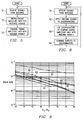
- the curve 92 is obtained using one antenna
- the curve 93 is obtained using two selectively switched antennas which share a common RF front end.
- the curve 94 corresponds to the receiver of FIGURE 3
- the curve 95 corresponds to the receiver of FIGURE 4
- the curve 96 corresponds to the receiver of FIGURE 7 .
- FIGURES 2-8 can be implemented, for example, by suitable modifications in software, hardware, or a combination of software and hardware, in conventional radio receivers that use antenna reception diversity, for example Bluetooth receivers.
Landscapes
- Engineering & Computer Science (AREA)
- Computer Networks & Wireless Communication (AREA)
- Signal Processing (AREA)
- Radio Transmission System (AREA)
- Mobile Radio Communication Systems (AREA)
- Details Of Aerials (AREA)
Claims (14)
- Ein Verfahren zum Erzeugen eines empfangenen Signals aus einer Mehrzahl von Antennensignalen (vi), entsprechend erzeugt von einer Mehrzahl von Antennen durch einen nichtlinearen Empfänger, wobei das Verfahren gekennzeichnet ist durch:Multiplizieren des Quadrats eines Schätzwerts schwächer werdender Amplitude (αi) für jedes Antennensignal mit dem zugeordneten Antennensignal (vi; v1i), um eine Mehrzahl von kombinierten Signalen zu erzeugen;
undSummieren der kombinierten Signale, um das empfangene Signal (r) zu erzeugen. - Das Verfahren aus Anspruch 1, das ferner das Verwenden eines linearen Empfängers (32) enthält, um Schätzwerte schwächer werdender Amplitude (αi; α1i), die den entsprechenden Antennensignalen (31) zugeordnet sind, zu erhalten.
- Das Verfahren aus Anspruch 2, enthaltend:das Verwenden eines Korrelators (44), um schwächer werdende Amplituden (α1i) abzuschätzen, die den entsprechenden Antennensignalen (v1i) zugeordnet sind.
- Das Verfahren aus Anspruch 3, das ferner enthält das Bestimmen von maximalen Korrelationswerten für die entsprechenden Antennensignale (vi) und das Bereitstellen der maximalen Korrelationswerte als Schätzwerte (α1i) schwächer werdender Amplitude.
- Das Verfahren aus Anspruch 1, wobei der Multiplikations-Schritt das Multiplizieren der Antennensignale (vi) mit entsprechend verzögerten Versionen der Antennensignale (vi) enthält, um so kombinierte Signale (v2i, v3i) zu erzeugen, die das Quadrat eines Schätzwerts schwächer werdender Amplitude (αi) für jedes Antennensignal, das mit dem zugeordneten Antennensignal multipliziert wurde, darstellen.
- Das Verfahren aus Anspruch 5, das ferner das Durchlaufen eines jeden Antennensignals (vi) durch einen Begrenzer (71) und ein Verzögerungselement (66) enthält, um verzögerte Versionen der Antennensignale zu erzeugen.
- Ein Gerät zum Erzeugen eines empfangenen Signals aus einer Mehrzahl von Antennensignalen (vi), entsprechend erzeugt von einer Mehrzahl von Antennen (N) durch einen nichtlinearen Empfänger, wobei das Gerät gekennzeichnet ist durch:Mittel (36; 42; 65; 65A) zum Multiplizieren des Quadrats eines Schätzwerts schwächer werdender Amplitude (αi) für jedes aus der Mehrzahl von Antennensignalen mit dem zugeordneten Antennensignal (vi; v1i), um eine Mehrzahl von kombinierten Signalen zu erzeugen;
undMittel zum Summieren (36, 42, 64, 72) der kombinierten Signale, um das empfangene Signal (r) zu erzeugen. - Das Gerät aus Anspruch 7, enthaltend
einen linearen Empfänger (32), der eingerichtet ist, um an seinem Ausgang Informationen zu erzeugen, die bezeichnend sind für Schätzwerte schwächer werdender Amplitude (αj), die dem jeweils entsprechenden Antennensignal (vi) zugeordnet sind; und
wobei die Mittel zum Multiplizieren und die Mittel zum Summieren eine Kombinationseinrichtung (36, 42) enthalten, die einen ersten Eingang zum Empfangen der Antennensignale (vi) und einen zweiten Eingang zum Empfangen der Schätzwerte schwächer werdender Amplitude (αj), die den entsprechenden Antennensignalen des linearen Empfängers zugeordnet sind, besitzt. - Das Gerät aus Anspruch 8, das eine Einrichtung zur Mittelwertbildung (35) einschließt, die zwischen dem Ausgang des genannten, linearen Empfängers (32) und dem zweiten Eingang der genannten Kombinationseinrichtung (36) angeschlossen ist, um die genannten Informationen, die an genanntem Ausgang bereitgestellt werden, zu mitteln, um die Schätzwerte schwächer werdender Amplitude (αi) zu erzeugen.
- Das Gerät aus Anspruch 8, das ferner einen Korrelator (44) enthält, der einen Eingang besitzt, der an genannten, ersten Eingang der Kombinationseinrichtung (42) angeschlossen ist, um maximale Korrelationswerte zu erzeugen, die den entsprechenden Antennensignalen zugeordnet sind, wobei der genannte Korrelator (44) einen Ausgang besitzt, der an genannten, zweiten Eingang der genannten Kombinationseinrichtung (42) angeschlossen ist, um die Korrelationswerte der genannten Kombinationseinrichtung (44) als die Schätzwerte der schwächer werdenden Amplitude (αi) bereitzustellen.
- Das Gerät aus Anspruch 10, das ferner eine Schwellwerteinrichtung (43) enthält, die zwischen genanntem, erstem Eingang der Kombinationseinrichtung (42) und dem Eingang des Korrelators (44) angeschlossen ist.
- Das Gerät aus Anspruch 7, das ferner enthält
einen Diskriminator (62), der einen Eingang zum Empfangen der Mehrzahl von Antennensignale (31) besitzt, wobei der genannte Diskriminator fähig ist zum Multiplizieren der Antennensignale (vi) mit entsprechend verzögerten Versionen der Antennensignale (vi), um so kombinierte Signale (v2i; v3i) zu erzeugen die das Quadrat darstellen eines Schätzwerts schwächer werdender Amplitude (αi) für jedes der Antennensignale multipliziert mit dem zugeordneten Antennensignal. - Das Gerät aus Anspruch 12, wobei der genannte Diskriminator einen Multiplizierer (65, 65A) einschließt, der einen ersten Eingang besitzt, der an den Eingang des Diskriminators (62) angeschlossen ist, wobei der genannte Multiplizierer (65, 65A) einen zweiten Eingang einschließt und der genannte Diskriminator (62) ferner ein Verzögerungselement (66) einschließt, das zwischen dem genannten Eingang des Diskriminators und genanntem, zweiten Eingang des Multiplizierers (65, 65A) angeschlossen ist.
- Das Gerät aus Anspruch 12, wobei der genannte Diskriminator (62) ferner einen Begrenzer (71) einschließt, der zwischen dem Eingang des Diskriminators (62) und dem Verzögerungselement (66) angeschlossen ist.
Applications Claiming Priority (4)
| Application Number | Priority Date | Filing Date | Title |
|---|---|---|---|
| US18463400P | 2000-02-24 | 2000-02-24 | |
| US184634P | 2000-02-24 | ||
| US634052 | 2000-08-08 | ||
| US09/634,052 US6714774B1 (en) | 2000-02-24 | 2000-08-08 | Antenna reception diversity in wireless communications |
Publications (2)
| Publication Number | Publication Date |
|---|---|
| EP1128576A1 EP1128576A1 (de) | 2001-08-29 |
| EP1128576B1 true EP1128576B1 (de) | 2010-10-06 |
Family
ID=26880343
Family Applications (1)
| Application Number | Title | Priority Date | Filing Date |
|---|---|---|---|
| EP01200714A Expired - Lifetime EP1128576B1 (de) | 2000-02-24 | 2001-02-26 | Diversität-Empfangsantenne in drahtlosen Kommunikationen |
Country Status (4)
| Country | Link |
|---|---|
| US (1) | US6714774B1 (de) |
| EP (1) | EP1128576B1 (de) |
| AT (1) | ATE484112T1 (de) |
| DE (1) | DE60143173D1 (de) |
Families Citing this family (6)
| Publication number | Priority date | Publication date | Assignee | Title |
|---|---|---|---|---|
| US7035350B2 (en) * | 2001-10-22 | 2006-04-25 | Broadcom Corporation | Bluetooth access code assisted initial DC estimation and frame synchronization |
| US7231000B2 (en) * | 2001-10-22 | 2007-06-12 | Broadcom Corporation | System and method for DC offset compensation and bit synchronization |
| US7251466B2 (en) * | 2004-08-20 | 2007-07-31 | Xceive Corporation | Television receiver including an integrated band selection filter |
| US20080195456A1 (en) * | 2006-09-28 | 2008-08-14 | Dudley Fitzpatrick | Apparatuses, Methods and Systems for Coordinating Personnel Based on Profiles |
| US8599824B2 (en) * | 2008-01-11 | 2013-12-03 | Broadcom Corporation | Method and system for bluetooth conditional synchronization |
| US11764857B2 (en) * | 2021-02-25 | 2023-09-19 | The Boeing Company | Systems and methods for multiple signal reception using receiver diversity |
Family Cites Families (10)
| Publication number | Priority date | Publication date | Assignee | Title |
|---|---|---|---|---|
| JP2982504B2 (ja) * | 1992-07-31 | 1999-11-22 | 日本電気株式会社 | 適応受信機 |
| JP2780576B2 (ja) * | 1992-08-05 | 1998-07-30 | 日本電気株式会社 | 干渉波除去装置 |
| DE69327837T2 (de) * | 1992-12-01 | 2000-10-12 | Koninklijke Philips Electronics N.V., Eindhoven | Teilband-Diversityübertragungssystem |
| MY113061A (en) * | 1994-05-16 | 2001-11-30 | Sanyo Electric Co | Diversity reception device |
| JP2561031B2 (ja) * | 1994-06-07 | 1996-12-04 | 日本電気株式会社 | 送受信装置 |
| SE503785C2 (sv) * | 1994-12-12 | 1996-09-02 | Ericsson Telefon Ab L M | Förfarande och anordning för att sammanlagra signaler |
| US5778310A (en) * | 1995-11-30 | 1998-07-07 | Northern Telecom Limited | Co-channel interference reduction |
| CA2180924C (en) | 1996-07-10 | 2003-04-08 | Nortel Networks Limited | Diversity path co-channel interference reduction |
| US5930293A (en) * | 1997-03-10 | 1999-07-27 | Lucent Technologies Inc. | Method and apparatus for achieving antenna receive diversity with wireless repeaters |
| US6505053B1 (en) * | 1999-11-05 | 2003-01-07 | At&T Corp. | Method for sinusoidal modeling and prediction of fast fading processes |
-
2000
- 2000-08-08 US US09/634,052 patent/US6714774B1/en not_active Expired - Lifetime
-
2001
- 2001-02-26 DE DE60143173T patent/DE60143173D1/de not_active Expired - Lifetime
- 2001-02-26 EP EP01200714A patent/EP1128576B1/de not_active Expired - Lifetime
- 2001-02-26 AT AT01200714T patent/ATE484112T1/de not_active IP Right Cessation
Also Published As
| Publication number | Publication date |
|---|---|
| DE60143173D1 (de) | 2010-11-18 |
| ATE484112T1 (de) | 2010-10-15 |
| US6714774B1 (en) | 2004-03-30 |
| EP1128576A1 (de) | 2001-08-29 |
Similar Documents
| Publication | Publication Date | Title |
|---|---|---|
| El-Hoiydi | Interference between Bluetooth networks-upper bound on the packet error rate | |
| EP1107475B1 (de) | Übertragungsschaltung und Verfahren zur Kommunikation | |
| US6396457B1 (en) | Concentrator for coupling local wireless networks to a wired network | |
| EP1183813B1 (de) | Zeit- und frequenzdiversität in fh/tdd systemen | |
| JP2992670B2 (ja) | 移動体通信装置 | |
| CN1082324C (zh) | 提高频谱效率的方法 | |
| US5481533A (en) | Hybrid intra-cell TDMA/inter-cell CDMA for wireless networks | |
| EP1362435A2 (de) | Verfahren zum erzeugen von diversität in einem kommunikationsnetzwerk | |
| US7376115B2 (en) | Method for generation of training sequence in channel estimation | |
| US7684465B1 (en) | Frequency hopping communication protocol | |
| US6961365B2 (en) | Method for signal processing in user equipment of CDMA mobile communication system | |
| WO2001015476A1 (en) | System and method for minimizing the loss of information in cordless communications | |
| EP1128576B1 (de) | Diversität-Empfangsantenne in drahtlosen Kommunikationen | |
| US5442660A (en) | Frequency hopping sequence using galois field | |
| KR20070103088A (ko) | Cdma 수신기와 관련 송신기를 동기화시키기 위한파일럿 신호를 검색하는 방법 | |
| US6970495B1 (en) | Adjustment of slave frequency hopping pattern to improve channel measurement opportunities in wireless communications | |
| EP1614232B1 (de) | Verfahren und vorrichtung zur erleichterung der signaldiskrimination in drahtlosen netzwerken durch anwenden bekannter frequenzoffsets | |
| US6931051B2 (en) | Frequency hopping wireless communication system with filtered adaptive slicer | |
| US6975684B1 (en) | Dynamic slave frequency selection for improving uplink frequency hopping wireless communications | |
| US7088785B2 (en) | Block level space time transmit diversity in wireless communications | |
| JP2001517394A (ja) | データ伝送方法、受信方法、及び受信器 | |
| EP3691139B1 (de) | Drahtlose kommunikationsvorrichtung zur durchführung von strahlformung unter frequenzsprung und zugehöriges drahtloses kommunikationsverfahren | |
| US7218680B1 (en) | Retransmission techniques for enhanced performance in fading wireless communication channels | |
| JP2011114636A (ja) | 近似同期cdma通信方式 | |
| JP2988258B2 (ja) | 移動体通信装置 |
Legal Events
| Date | Code | Title | Description |
|---|---|---|---|
| PUAI | Public reference made under article 153(3) epc to a published international application that has entered the european phase |
Free format text: ORIGINAL CODE: 0009012 |
|
| 17P | Request for examination filed |
Effective date: 20010226 |
|
| AK | Designated contracting states |
Kind code of ref document: A1 Designated state(s): AT BE CH CY DE DK ES FI FR GB GR IE IT LI LU MC NL PT SE TR |
|
| AX | Request for extension of the european patent |
Free format text: AL;LT;LV;MK;RO;SI |
|
| AKX | Designation fees paid |
Free format text: AT BE CH CY DE DK ES FI FR GB GR IE IT LI LU MC NL PT SE TR |
|
| 17Q | First examination report despatched |
Effective date: 20071221 |
|
| GRAP | Despatch of communication of intention to grant a patent |
Free format text: ORIGINAL CODE: EPIDOSNIGR1 |
|
| GRAS | Grant fee paid |
Free format text: ORIGINAL CODE: EPIDOSNIGR3 |
|
| GRAA | (expected) grant |
Free format text: ORIGINAL CODE: 0009210 |
|
| AK | Designated contracting states |
Kind code of ref document: B1 Designated state(s): AT BE CH CY DE DK ES FI FR GB GR IE IT LI LU MC NL PT SE TR |
|
| REG | Reference to a national code |
Ref country code: GB Ref legal event code: FG4D |
|
| REG | Reference to a national code |
Ref country code: CH Ref legal event code: EP |
|
| REG | Reference to a national code |
Ref country code: IE Ref legal event code: FG4D |
|
| REF | Corresponds to: |
Ref document number: 60143173 Country of ref document: DE Date of ref document: 20101118 Kind code of ref document: P |
|
| REG | Reference to a national code |
Ref country code: NL Ref legal event code: T3 |
|
| PG25 | Lapsed in a contracting state [announced via postgrant information from national office to epo] |
Ref country code: AT Free format text: LAPSE BECAUSE OF FAILURE TO SUBMIT A TRANSLATION OF THE DESCRIPTION OR TO PAY THE FEE WITHIN THE PRESCRIBED TIME-LIMIT Effective date: 20101006 Ref country code: SE Free format text: LAPSE BECAUSE OF FAILURE TO SUBMIT A TRANSLATION OF THE DESCRIPTION OR TO PAY THE FEE WITHIN THE PRESCRIBED TIME-LIMIT Effective date: 20101006 Ref country code: PT Free format text: LAPSE BECAUSE OF FAILURE TO SUBMIT A TRANSLATION OF THE DESCRIPTION OR TO PAY THE FEE WITHIN THE PRESCRIBED TIME-LIMIT Effective date: 20110207 Ref country code: FI Free format text: LAPSE BECAUSE OF FAILURE TO SUBMIT A TRANSLATION OF THE DESCRIPTION OR TO PAY THE FEE WITHIN THE PRESCRIBED TIME-LIMIT Effective date: 20101006 |
|
| PG25 | Lapsed in a contracting state [announced via postgrant information from national office to epo] |
Ref country code: BE Free format text: LAPSE BECAUSE OF FAILURE TO SUBMIT A TRANSLATION OF THE DESCRIPTION OR TO PAY THE FEE WITHIN THE PRESCRIBED TIME-LIMIT Effective date: 20101006 Ref country code: GR Free format text: LAPSE BECAUSE OF FAILURE TO SUBMIT A TRANSLATION OF THE DESCRIPTION OR TO PAY THE FEE WITHIN THE PRESCRIBED TIME-LIMIT Effective date: 20110107 |
|
| PG25 | Lapsed in a contracting state [announced via postgrant information from national office to epo] |
Ref country code: ES Free format text: LAPSE BECAUSE OF FAILURE TO SUBMIT A TRANSLATION OF THE DESCRIPTION OR TO PAY THE FEE WITHIN THE PRESCRIBED TIME-LIMIT Effective date: 20110117 |
|
| PLBE | No opposition filed within time limit |
Free format text: ORIGINAL CODE: 0009261 |
|
| STAA | Information on the status of an ep patent application or granted ep patent |
Free format text: STATUS: NO OPPOSITION FILED WITHIN TIME LIMIT |
|
| PG25 | Lapsed in a contracting state [announced via postgrant information from national office to epo] |
Ref country code: DK Free format text: LAPSE BECAUSE OF FAILURE TO SUBMIT A TRANSLATION OF THE DESCRIPTION OR TO PAY THE FEE WITHIN THE PRESCRIBED TIME-LIMIT Effective date: 20101006 |
|
| 26N | No opposition filed |
Effective date: 20110707 |
|
| PG25 | Lapsed in a contracting state [announced via postgrant information from national office to epo] |
Ref country code: MC Free format text: LAPSE BECAUSE OF NON-PAYMENT OF DUE FEES Effective date: 20110228 |
|
| REG | Reference to a national code |
Ref country code: CH Ref legal event code: PL |
|
| PG25 | Lapsed in a contracting state [announced via postgrant information from national office to epo] |
Ref country code: LI Free format text: LAPSE BECAUSE OF NON-PAYMENT OF DUE FEES Effective date: 20110228 Ref country code: CH Free format text: LAPSE BECAUSE OF NON-PAYMENT OF DUE FEES Effective date: 20110228 |
|
| REG | Reference to a national code |
Ref country code: DE Ref legal event code: R097 Ref document number: 60143173 Country of ref document: DE Effective date: 20110707 |
|
| REG | Reference to a national code |
Ref country code: DE Ref legal event code: R082 Ref document number: 60143173 Country of ref document: DE |
|
| PG25 | Lapsed in a contracting state [announced via postgrant information from national office to epo] |
Ref country code: IT Free format text: LAPSE BECAUSE OF FAILURE TO SUBMIT A TRANSLATION OF THE DESCRIPTION OR TO PAY THE FEE WITHIN THE PRESCRIBED TIME-LIMIT Effective date: 20101006 |
|
| PG25 | Lapsed in a contracting state [announced via postgrant information from national office to epo] |
Ref country code: CY Free format text: LAPSE BECAUSE OF FAILURE TO SUBMIT A TRANSLATION OF THE DESCRIPTION OR TO PAY THE FEE WITHIN THE PRESCRIBED TIME-LIMIT Effective date: 20101006 Ref country code: LU Free format text: LAPSE BECAUSE OF NON-PAYMENT OF DUE FEES Effective date: 20110226 |
|
| PG25 | Lapsed in a contracting state [announced via postgrant information from national office to epo] |
Ref country code: TR Free format text: LAPSE BECAUSE OF FAILURE TO SUBMIT A TRANSLATION OF THE DESCRIPTION OR TO PAY THE FEE WITHIN THE PRESCRIBED TIME-LIMIT Effective date: 20101006 |
|
| REG | Reference to a national code |
Ref country code: FR Ref legal event code: PLFP Year of fee payment: 16 |
|
| PGFP | Annual fee paid to national office [announced via postgrant information from national office to epo] |
Ref country code: DE Payment date: 20160302 Year of fee payment: 16 Ref country code: IE Payment date: 20160126 Year of fee payment: 16 |
|
| PGFP | Annual fee paid to national office [announced via postgrant information from national office to epo] |
Ref country code: NL Payment date: 20160205 Year of fee payment: 16 Ref country code: FR Payment date: 20160125 Year of fee payment: 16 Ref country code: GB Payment date: 20160127 Year of fee payment: 16 |
|
| REG | Reference to a national code |
Ref country code: DE Ref legal event code: R119 Ref document number: 60143173 Country of ref document: DE |
|
| REG | Reference to a national code |
Ref country code: NL Ref legal event code: MM Effective date: 20170301 |
|
| GBPC | Gb: european patent ceased through non-payment of renewal fee |
Effective date: 20170226 |
|
| REG | Reference to a national code |
Ref country code: IE Ref legal event code: MM4A |
|
| PG25 | Lapsed in a contracting state [announced via postgrant information from national office to epo] |
Ref country code: NL Free format text: LAPSE BECAUSE OF NON-PAYMENT OF DUE FEES Effective date: 20170301 |
|
| REG | Reference to a national code |
Ref country code: FR Ref legal event code: ST Effective date: 20171031 |
|
| PG25 | Lapsed in a contracting state [announced via postgrant information from national office to epo] |
Ref country code: DE Free format text: LAPSE BECAUSE OF NON-PAYMENT OF DUE FEES Effective date: 20170901 Ref country code: FR Free format text: LAPSE BECAUSE OF NON-PAYMENT OF DUE FEES Effective date: 20170228 |
|
| PG25 | Lapsed in a contracting state [announced via postgrant information from national office to epo] |
Ref country code: GB Free format text: LAPSE BECAUSE OF NON-PAYMENT OF DUE FEES Effective date: 20170226 Ref country code: IE Free format text: LAPSE BECAUSE OF NON-PAYMENT OF DUE FEES Effective date: 20170226 |