EP1132169A2 - A control unit for window frames, a method for production of the control unit and a machine which implements this method - Google Patents
A control unit for window frames, a method for production of the control unit and a machine which implements this method Download PDFInfo
- Publication number
- EP1132169A2 EP1132169A2 EP01830151A EP01830151A EP1132169A2 EP 1132169 A2 EP1132169 A2 EP 1132169A2 EP 01830151 A EP01830151 A EP 01830151A EP 01830151 A EP01830151 A EP 01830151A EP 1132169 A2 EP1132169 A2 EP 1132169A2
- Authority
- EP
- European Patent Office
- Prior art keywords
- section bar
- mobile frame
- machining
- single rod
- frame
- Prior art date
- Legal status (The legal status is an assumption and is not a legal conclusion. Google has not performed a legal analysis and makes no representation as to the accuracy of the status listed.)
- Granted
Links
Images

Classifications
-
- E—FIXED CONSTRUCTIONS
- E05—LOCKS; KEYS; WINDOW OR DOOR FITTINGS; SAFES
- E05C—BOLTS OR FASTENING DEVICES FOR WINGS, SPECIALLY FOR DOORS OR WINDOWS
- E05C9/00—Arrangements of simultaneously actuated bolts or other securing devices at well-separated positions on the same wing
- E05C9/02—Arrangements of simultaneously actuated bolts or other securing devices at well-separated positions on the same wing with one sliding bar for fastening when moved in one direction and unfastening when moved in opposite direction; with two sliding bars moved in the same direction when fastening or unfastening
-
- B—PERFORMING OPERATIONS; TRANSPORTING
- B23—MACHINE TOOLS; METAL-WORKING NOT OTHERWISE PROVIDED FOR
- B23P—METAL-WORKING NOT OTHERWISE PROVIDED FOR; COMBINED OPERATIONS; UNIVERSAL MACHINE TOOLS
- B23P15/00—Making specific metal objects by operations not covered by a single other subclass or a group in this subclass
-
- B—PERFORMING OPERATIONS; TRANSPORTING
- B23—MACHINE TOOLS; METAL-WORKING NOT OTHERWISE PROVIDED FOR
- B23P—METAL-WORKING NOT OTHERWISE PROVIDED FOR; COMBINED OPERATIONS; UNIVERSAL MACHINE TOOLS
- B23P2700/00—Indexing scheme relating to the articles being treated, e.g. manufactured, repaired, assembled, connected or other operations covered in the subgroups
- B23P2700/08—Fittings for doors and windows of buildings
Definitions
- the present invention relates to a control unit for window frames, a method for production of the control unit and a machine which implements this method.
- control unit allows the achievement of the mobile frame configurations (side-hung turning opening, tilting opening, closed) by operation of a handle on the outer surface of the mobile frame itself.
- the control unit consists of a pair of rod segments (a flat section of a bar) connected by a connecting element or, as it is called in the sector, a drive unit, which is placed between the two segments and attached to them using pins, normally present on the drive unit, which may be inserted in the holes in the corresponding ends of the segments.
- the two segments also have other seats or holes, made close to the ends opposite those attached to the drive unit, for their connection, during frame assembly, to the moving parts which open and close the mobile frame (push bolts or lock terminals) and to drive elements (such as corner drives) for mobile frame tilting opening.
- the control unit structured in this way is obtained using a method according to which the rod segments are produced using a special cutting machine, starting with a section bar with a suitable cross-section which can be attached with a matching fit in a channel present on the frame section.
- the length of the segments depends on the dimensions (height) of the mobile frame in which they will be inserted. Once cut, the segments are machined to create the seats and/or holes mentioned, which are needed in order to connect them to the drive unit and to the opening/closing and drive parts.
- the aim of the present invention is, therefore, to overcome the above-mentioned disadvantages by providing a control unit whose structure is extremely simplified, thus facilitating assembly and so making the entire unit more economically viable.
- Another aim of the present invention is to provide a method for production of the control unit which is extremely fast and precise and a machine which implements this method.
- the present invention achieves the preset aims with a control unit for window frames, the latter comprising a fixed frame and a mobile frame with more than one opening configuration.
- the control unit consists of a single rod which extends substantially the height of the mobile frame and can be inserted in a sliding channel in one of the uprights of the mobile frame, forming means which transmit the sliding movement; drive means which may be attached to a control handle and at least part of the control elements for moving the mobile frame relative to the fixed frame.
- the preset aims are also accordingly achieved by a method for production of the control unit comprising the steps, which may be carried out simultaneously or in succession, of feeding a section bar with a cross-section that makes a matching fit with the sliding channel in an operating direction; performing a plurality of machining operations on the section bar, using appropriate means, designed to produce a series of features in the shape and/or profile of the section bar, so as to form at least the drive means and part of the control elements, and cutting from the section bar a portion comprising the above-mentioned features, to form a single rod whose length is substantially equal to the height of the mobile frame.
- This method is implemented by a machine comprising a first station which feeds the section bar in an operating direction; a second station which machines the section bar, this station having a plurality of machining units designed to allow the simultaneous or successive creation of a series of features in the shape and/or profile of the section bar, so as to form at least the drive means and part of the control elements, and cutting to size of the section bar, to form a single rod with the drive means and at least part of the control elements.
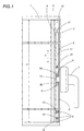
- control unit disclosed is fitted on metal frames of the type comprising a fixed frame 1 and a mobile frame 2, with height H, which opens according to one or more configurations.
- a frame with both side-hung turning and tilting opening is considered, although this does not mean that the control unit disclosed cannot be fitted on frames with simple side-hung turning opening or tilting opening only, or on frames with sliding opening.
- the control unit labelled 3 as a whole, fits in such a way that it can slide inside a channel 4 on one of the uprights 5 of the section (which determines the height H referred to above) and forms part of the mobile frame 2.
- This control unit 3 comprises drive means 6 which may be attached to a control handle 7 mounted on the mobile frame 2 and which operates a control lever 13, and means 8 for transmitting a sliding movement by the drive means 6 in both directions and along the channel 4 (see arrow F in Figure 1), obtained by movement of the handle 7.
- the transmission means 8 are attached to the drive means 6 and, respectively, to elements 9 for connecting and/or elements 10 for moving the mobile frame 2 relative to the fixed frame 1, in order to allow achievement of the mobile frame 2 opening or closing configurations.
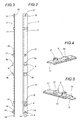
- control unit 3 comprises a single rod 11 which extends substantially the height H of the mobile frame 2, forming the means 8 which transmit the sliding movement, the drive means 6 and at least part of the control elements 10.
- the single rod 11 also has means 12 for connection to other mobile frame 2 control elements 10.
- the drive means 6 comprise a pair of first projections 6a and 6b, opposite one another, consisting of portions of the surface of the single rod 11 and forming elements which intercept the handle 7 control lever 13 in both directions.
- Figure 5 shows one of the ends of the single rod 11, with tapering 14 of the cross-section of the rod 11, designed to form a control end piece, for rotation, for the mobile frame 2, when it is in the tilting opening configuration, and forming one of the control elements 10.
- the taper 14 consists of two arced notches, positioned opposite one another, at the end of the rod 11, forming a sort of double pivot zone for the mobile frame 2.
- Figure 5 also shows how, again close to the tapered end 14, the single rod 11 has a second projection 15 consisting of a portion of the surface of the single rod 11 designed to form another control element 10 needed for mobile frame 2 tilting opening.
- the rod 11 has a first hole 16 at the end opposite that with the taper 14, forming the above-mentioned means 12 for connection to control elements 10 which, in the embodiment illustrated, consist of a corner drive with a first pin 17 for connection to the rod 11.
- the single rod 11 has a second hole 18 between the second projection 15 and the tapered end 14, designed to allow the insertion on the single rod 11 of a second pin 19, forming one of the connecting elements 9, for making contact with and holding the mobile frame 2 against the fixed frame 1 when the window frame is in the closed configuration.
- the single rod 11 may have a third hole 20, close to the pair of first projections 6a and 6b, designed to allow the insertion of a third pin 21 for making contact with and holding the mobile frame 2 against the fixed frame 1 when the window frame is in the closed configuration.
- the basic control unit 3 is obtained, although during machining of the section bar, a first boring operation is preferably carried out, to make at least the first hole 16 for connecting other control elements 10.
- main machining operations include the following:
- This method may be implemented using a machine, illustrated in the diagram in Figure 6, comprising:
- the first station 31, located upstream of the second station 32 relative to the operating direction L, comprises a section bar P infeed channel 34 and a unit 35 for the bilateral pickup and feed of the section bar P connected to the control unit 33.
- the pickup unit 35 may consist of a pair of rollers 35a and 35b positioned opposite one another and in contact with both sides of the section bar P.
- One of the rollers, 35a is motor-powered and is connected to a counting element 26 (for example, an encoder), which is controlled directly by the control unit 33, for checking the length of the section bar P fed in.
- a counting element 26 for example, an encoder
- the second station 32 for machining the section bar P, may comprise a support frame 37 for the machining units 30, located above the section bar P fed in and positioned one after another.
- This frame 37 may be controlled by means 38 (for example a cylinder 38c) which move it between a non-operating position, in which the units 30 are distanced from the section bar P (see Figure 6), and an operating position, in which the units 30 are close to the section bar P (see arrow Fl and Figure 7).
- means 38 for example a cylinder 38c which move it between a non-operating position, in which the units 30 are distanced from the section bar P (see Figure 6), and an operating position, in which the units 30 are close to the section bar P (see arrow Fl and Figure 7).
- an activation element 39 controlled by the control unit 33, and designed to allow the unit 30 to perform another operating stroke so that, when the frame 37 is in the operating position, the machining unit makes contact with the section bar P (see arrow F2 in Figure 7).
- This activation element 39 for each machining unit 30 may be magnetic and activated by means of the unit 33 according to a preset program.
- the second station 32 may comprise a support and sliding base 40, opposite the machining units 30, consisting of a support track 41 for the section bar P. This track is designed to form an element which opposes the machining units 30 during the cutting downstroke.
- each of the machining units 30 (in Figure 6, for example, five units are illustrated, although this number may vary according to requirements) consists of a cutting head 42 shaped in such a way as to produce the single feature in the shape and/or profile of the section bar P, bore a hole in it, or cut the section bar.
- the control unit 33 may consist of a microprocessor unit which the operator may programme using a keyboard according to the various machining requirements and the length of the rod 11.
- control unit the method for producing the unit and the machine described above, therefore, fulfil the preset aims thanks to the rationalisation and unification of a set of elements which, in the known embodiments, are separate and are made with successive machining operations.
Landscapes
- Engineering & Computer Science (AREA)
- Mechanical Engineering (AREA)
- Wing Frames And Configurations (AREA)
- Automatic Assembly (AREA)
- Manufacture Of Motors, Generators (AREA)
- Power-Operated Mechanisms For Wings (AREA)
- Numerical Control (AREA)
- Automobile Manufacture Line, Endless Track Vehicle, Trailer (AREA)
- Multi-Process Working Machines And Systems (AREA)
Abstract
Description
- Figure 1 is a schematic front view of a metal frame in the side-hung turning opening configuration, equipped with a control unit, in accordance with the present invention;
- Figures 2 and 3 are respectively a top plan view and a side view of the control unit disclosed, with some parts cut away to better illustrate others;
- Figures 4 and 5 are perspective views of details of the control unit illustrated in Figure 2;
- Figure 6 is a diagram of a machine which produces the control unit illustrated in the previous figures;
- Figure 7 is a detail of the machine illustrated in Figure 6.
- feeding a section bar P with a cross-section
which makes a matching fit with the
channel 4 in an operating direction L (see Figure 6); - performing a plurality of machining operations on
the section bar P, using means 30 (described
below), designed to make a series of features in
the shape and/or profile of the section bar P, to
form at least the drive means 6 and part of the
control elements 10; - cutting from the section bar P of a portion,
comprising the above-mentioned features, which
forms the
single rod 11 whose length is substantially equal to the height H of themobile frame 2.
- a cutting operation, on the surface of the
section bar P, to produce the pair of
first projections - another cutting operation on the surface of the
section bar P, for forming the
second projection 15 which is one of thecontrol elements 10; - another cutting operation at one end of the
section bar P, for tapering 14 the end so as to
create another
control element 10.
- a
first station 31, which feeds a continuous section bar P in the operating direction L (see arrow L); - a
second station 32, for machining the section bar P, equipped with a plurality ofmachining units 30 designed to allow simultaneous or successive operations for making a series of features in the shape and/or profile of the section bar P, to form the drive means 6 and part of thecontrol elements 10, and cutting to size of the section bar P to form thesingle rod 11 equipped with thedrive means 6 and part of thecontrol elements 10; - a
control unit 33 for thefeed station 31 and themachining units 30, designed to activate themachining units 30 according to the final length of thesingle rod 11, the type of machining to be done and section bar P feed in thesecond station 32.
Claims (22)
- A control unit for window frames comprising a fixed frame (1) and mobile frame (2), having a height (H) and opening in one or more configurations; the control unit (3) comprising, sliding in a channel (4) in one of the uprights (5) of the section forming the mobile frame (2), drive means (6) which may be attached to a control handle (7) mounted on the mobile frame (2), and means (8) for transmitting a sliding movement by the drive means (6) in both directions and along the channel (4), obtained by movement of the handle (7); the transmission means (8) being attached to the drive means (6) and, respectively, to connecting elements (9) and/or control elements (10) for the mobile frame (2) relative to the fixed frame (1), allowing the mobile frame (2) to move to the opening or closing configurations, the control unit being characterised in that it comprises a single rod (11) extending substantially the height (H) of the mobile frame (2), it being possible to insert the rod in the channel (4), the rod forming the means (8) which transmit the sliding movement, the drive means (6) and at least part of the control elements (10).
- The unit according to claim 1, characterised in that the single rod (11) is equipped with means (12) for connecting the mobile frame (2) to other control elements (10).
- The unit according to claims 1 and 2, characterised in that the drive means (6) comprise a pair of first projections (6a, 6b), opposite one another, being formed from portions of the surface of the single rod (11) and forming elements which intercept the handle (7) control lever (13) in both directions.
- The unit according to claims 1 to 3, characterised in that, at least at one end, the single rod (11) has a taper (14) in its cross-section, being designed to create a connection for rotation of the mobile frame (2) in a tilting opening configuration and forming part of the control elements (10).
- The unit according to claim 4, characterised in that, at least at the tapered end (14), the single rod (11) has a second projection (15) on a portion of the surface of the single rod (11), being designed to form a contact element, when the mobile frame (2) is in a tilting opening configuration and constituting one of the control elements (10).
- The unit according to claims 1 to 5, characterised in that the single rod (11) has at least one first hole (16) at the end opposite the taper (14) forming the means (12) for connecting the mobile frame (2) to other control elements (10), comprising a first connecting pin (17).
- The unit according to claims 1 to 6, characterised in that the single rod (11) has a second hole (18) between the second projection (15) and the tapered end (14), being designed to allow the insertion of a second pin (19) which is one of the connecting elements (9) on the single rod (11).
- The unit according to claims 1 to 7, characterised in that the single rod (11) has a third hole (20), close to the pair of first projections (6a, 6b), being designed to allow the insertion of a third pin (21) which is another connecting element (9) on the single rod (11).
- A method for producing a control unit for window frames of the type comprising a fixed frame (1) and mobile frame (2), having a height (H) and opening in one or more configurations; the control unit (3) comprising, sliding in a channel (4) in one of the uprights (5) of the section forming the mobile frame (2), drive means (6) which may be attached to a control handle (7) mounted on the mobile frame (2), and means (8) for transmitting a sliding movement by the drive means (6) in both directions and along the channel (4), obtained by movement of the handle (7); the transmission means (8) being attached to the drive means (6) and, respectively, to connecting elements (9) and/or control elements (10) for the mobile frame (2) relative to the fixed frame (1), allowing the mobile frame (2) to move to the opening or closing configurations, the method being characterised in that it comprises the following steps, which may be simultaneous or successive:feeding a section bar (P) with a cross-section which makes a matching fit with the channel (4) in an operating direction (L);performing a plurality of machining operations on the section bar (P) using means (30) designed to make a series of features in the shape and/or profile of the section bar (P), for forming at least the drive means (6) and part of the control elements (10);cutting from the section bar (P) of a portion, comprising the above-mentioned features, which forms the single rod (11) whose length is substantially equal to the height (H) of the mobile frame 2.
- The method according to claim 9, characterised in that the step of machining the single rod (11) comprises at least one boring operation, to produce at least one seat (16) for connecting another control element (10).
- The method according to claim 9, characterised in that the machining step comprises an operation for cutting the surface of the section bar (P), producing a pair of first projections (6a, 6b) which are opposite one another and form the drive means (6).
- The method according to claim 9, characterised in that the machining step comprises an operation for cutting the surface of the section bar (P), forming a second projection (15) which is one of the control elements (10).
- The method according to claim 9, characterised in that the machining step comprises an operation for cutting one end of the section bar (P), being designed to form a taper (14) at said end and form one of the control elements (10).
- The method according to claims 9 and 10, characterised in that the machining step comprises another boring operation for making at least one seat (18) for the insertion of a contact element or pin (19) which can be attached to the single rod (11).
- The method according to claims 9 and 10, characterised in that the machining step comprises another boring operation for making at least one seat (20) for the insertion of a contact element or pin (21) which can be attached to the single rod (11).
- A machine for producing a control unit for window frames of the type comprising a fixed frame (1) and mobile frame (2), having a height (H) and opening in one or more configurations; the control unit (3) comprising, sliding in a channel (4) in one of the uprights (5) of the section forming the mobile frame (2), drive means (6) which may be attached to a control handle (7) mounted on the mobile frame (2), and means (8) for transmitting a sliding movement by the drive means (6) in both directions and along the channel (4), obtained by movement of the handle (7); the transmission means (8) being attached to the drive means (6) and, respectively, to connecting elements (9) and/or control elements (10) for the mobile frame (2) relative to the fixed frame (1), allowing the mobile frame (2) to move to the opening or closing configurations, the machine being characterised in that it comprises:a first station (31), for feeding a section bar (P) in an operating direction (L);a second station (32), for machining the section bar (P), equipped with a plurality of machining units (30) designed to allow simultaneous or successive operations for making a series of features in the shape and/or profile of the section bar (P), for forming the drive means (6) and part of the control elements (10), and cutting to size of the section bar (P) to form the single rod (11) equipped with the drive means (6) and the part of the control elements (10);a control unit (33) for the feed station (31) and the machining units (30), for activating the machining units (30) according to the final length of the single rod (11), the type of machining to be done and section bar (P) feed in the second station (32).
- The machine according to claim 16, characterised in that the first station (31) comprises an infeed channel (34) for the section bar (P) and a unit (35) for the bilateral pickup and feed of the section bar (P), being connected to the control unit (33).
- The machine according to claim 16, characterised in that the bilateral pickup unit (35) consists of a pair of rollers (35a, 35b), being opposite one another and on both sides of the section bar (P); at least one of the rollers (35a, 35b) being motor-powered and connected to a counting element (36) controlled by the control unit (33).
- The machine according to claim 16, characterised in that the second station (32) for machining the section bar (P) comprises a support frame (37) for the machining units (30), the latter being located above the section bar (P) fed in and positioned one after another; the frame (37) being controlled by means (38) which move it between a non-operating position, in which the units (30) are distanced from the section bar (P), and an operating position, in which the units (30) are close to the section bar (P); between the frame (37) and each of the units (30) there being an activation element (39), controlled by the control unit (33), which allows the unit (30) to perform another operating stroke so that, when the frame (37) is in the operating position, the machining unit makes contact with the section bar (P).
- The machine according to claim 19, characterised in that the activation element (39) of each machining unit (30) is of the magnetic type.
- The machine according to claims 15 to 19, characterised in that the second station (32) comprises a support base (40) opposite the machining units (30), consisting of a support track (41) for the section bar (P); the track being designed to form an element which opposes the machining units (30).
- The machine according to claim 16, characterised in that each of the machining units (30) consists of a cutting head (42) shaped in such a way as to produce a feature in the shape and/or profile of the section bar (P) or to cut the section bar.
Applications Claiming Priority (2)
| Application Number | Priority Date | Filing Date | Title |
|---|---|---|---|
| ITBO000117 | 2000-03-07 | ||
| IT2000BO000117A ITBO20000117A1 (en) | 2000-03-07 | 2000-03-07 | MANEUVERING GROUP FOR WINDOWS, METHOD FOR THE CREATION OF THE MANEUVERING GROUP AND MACHINE IMPLEMENTING THIS METHOD. |
Publications (3)
| Publication Number | Publication Date |
|---|---|
| EP1132169A2 true EP1132169A2 (en) | 2001-09-12 |
| EP1132169A3 EP1132169A3 (en) | 2002-11-27 |
| EP1132169B1 EP1132169B1 (en) | 2004-07-28 |
Family
ID=11438272
Family Applications (1)
| Application Number | Title | Priority Date | Filing Date |
|---|---|---|---|
| EP01830151A Expired - Lifetime EP1132169B1 (en) | 2000-03-07 | 2001-03-06 | A control unit for window frames, a method for production of the control unit and a machine which implements this method |
Country Status (5)
| Country | Link |
|---|---|
| EP (1) | EP1132169B1 (en) |
| AT (1) | ATE271952T1 (en) |
| DE (1) | DE60104460T2 (en) |
| ES (1) | ES2225458T3 (en) |
| IT (1) | ITBO20000117A1 (en) |
Cited By (5)
| Publication number | Priority date | Publication date | Assignee | Title |
|---|---|---|---|---|
| EP1232830A3 (en) * | 2001-02-14 | 2002-11-27 | GSG INTERNATIONAL S.p.A. | A method for the production of accessories for window frames and the equipment for implementing the method |
| EP1495832A1 (en) * | 2003-07-10 | 2005-01-12 | Siegenia-Aubi Kg | Device for mounting an espagnolette fitting to a frame member or frame of a window or a door |
| EP1454708A3 (en) * | 2003-03-05 | 2006-04-19 | GSG INTERNATIONAL S.p.A. | Apparatus for making operating units for doors or windows |
| EP1460216A3 (en) * | 2003-03-05 | 2006-08-02 | GSG International S.p.A. | An operating unit for doors and windows |
| ITBO20080663A1 (en) * | 2008-10-30 | 2010-04-30 | Gsg Int Spa | CLOSING DEVICE FOR WINDOWS. |
Families Citing this family (2)
| Publication number | Priority date | Publication date | Assignee | Title |
|---|---|---|---|---|
| US11866968B2 (en) * | 2019-09-17 | 2024-01-09 | Truth Hardware Corporation | Tie bar and guide for casement window |
| US12163361B2 (en) * | 2020-03-17 | 2024-12-10 | Truth Hardware Corporation | Roll-form tie bar and guide for casement window |
Family Cites Families (9)
| Publication number | Priority date | Publication date | Assignee | Title |
|---|---|---|---|---|
| DE1149635B (en) * | 1960-04-26 | 1963-05-30 | Wilhelm Frank | Driving rod for fittings of Genstern, doors or the like equipped with a gear. |
| DE3831529C2 (en) * | 1988-09-16 | 1994-05-05 | Winkhaus Fa August | Espagnolette lock |
| FR2664932A1 (en) * | 1990-07-20 | 1992-01-24 | Bezault Sa | Rod-and-espagnolette device for locking casements when they are closed |
| DE4207345C2 (en) * | 1992-03-07 | 2002-10-10 | Melchert Beschlaege | Locking handle fitting on windows, doors or the like to be operated by means of a handle |
| DE4312293A1 (en) * | 1993-04-15 | 1994-10-20 | Schueco Int Kg | Coupling device of a push rod or a fitting driver for a locking rod of a window or a door guided in grooves |
| DE4328205C2 (en) * | 1993-08-21 | 1998-01-29 | Federhenn Maschinen Gmbh | Device for storing and feeding long, bar-shaped workpieces to a processing station |
| IT1280227B1 (en) * | 1995-03-22 | 1998-01-05 | Giesse Spa | CLOSING ELEMENT FOR METAL FRAMES |
| FR2747723B1 (en) * | 1996-04-23 | 1998-06-05 | Ferco Int Usine Ferrures | CREMONE AND CREMONE ROD |
| DE19906758A1 (en) * | 1998-02-20 | 1999-10-14 | Lemuth Gmbh | Fitting for window casement and door-leaf |
-
2000
- 2000-03-07 IT IT2000BO000117A patent/ITBO20000117A1/en unknown
-
2001
- 2001-03-06 EP EP01830151A patent/EP1132169B1/en not_active Expired - Lifetime
- 2001-03-06 ES ES01830151T patent/ES2225458T3/en not_active Expired - Lifetime
- 2001-03-06 AT AT01830151T patent/ATE271952T1/en not_active IP Right Cessation
- 2001-03-06 DE DE60104460T patent/DE60104460T2/en not_active Expired - Lifetime
Cited By (7)
| Publication number | Priority date | Publication date | Assignee | Title |
|---|---|---|---|---|
| EP1232830A3 (en) * | 2001-02-14 | 2002-11-27 | GSG INTERNATIONAL S.p.A. | A method for the production of accessories for window frames and the equipment for implementing the method |
| EP1454708A3 (en) * | 2003-03-05 | 2006-04-19 | GSG INTERNATIONAL S.p.A. | Apparatus for making operating units for doors or windows |
| EP1460216A3 (en) * | 2003-03-05 | 2006-08-02 | GSG International S.p.A. | An operating unit for doors and windows |
| EP1495832A1 (en) * | 2003-07-10 | 2005-01-12 | Siegenia-Aubi Kg | Device for mounting an espagnolette fitting to a frame member or frame of a window or a door |
| ITBO20080663A1 (en) * | 2008-10-30 | 2010-04-30 | Gsg Int Spa | CLOSING DEVICE FOR WINDOWS. |
| WO2010049750A1 (en) * | 2008-10-30 | 2010-05-06 | Gsg International S.P.A. | A device for connecting door and window operating units |
| US9151094B2 (en) | 2008-10-30 | 2015-10-06 | Gsg International S.P.A. | Device for connecting door and window operating units |
Also Published As
| Publication number | Publication date |
|---|---|
| ES2225458T3 (en) | 2005-03-16 |
| ATE271952T1 (en) | 2004-08-15 |
| DE60104460T2 (en) | 2005-08-04 |
| EP1132169B1 (en) | 2004-07-28 |
| ITBO20000117A1 (en) | 2001-09-07 |
| DE60104460D1 (en) | 2004-09-02 |
| EP1132169A3 (en) | 2002-11-27 |
Similar Documents
| Publication | Publication Date | Title |
|---|---|---|
| US6178857B1 (en) | Method of end trimming of blinds | |
| US6758120B2 (en) | Blind cut down apparatus | |
| EP0850346B1 (en) | End trimming apparatus for venetian blinds | |
| US6196099B1 (en) | End trimming apparatus for blinds | |
| CA2243369C (en) | Dual mini-blind cutter | |
| DE3318653A1 (en) | DEVICE FOR CUTTING WITH SIMULTANEOUS TRAINING OF CUTS | |
| EP1132169B1 (en) | A control unit for window frames, a method for production of the control unit and a machine which implements this method | |
| KR20130044424A (en) | Ornament chain manufacturing machine and its used ornament chain manufacturing method for scratch removement and process reduction | |
| US5574651A (en) | Method and system for machining muntin sections and seating bars | |
| US4612700A (en) | Component insertion apparatus | |
| EP1236610B1 (en) | Method for making a lumbar support | |
| US5535497A (en) | High speed automatic terminal-pressing machine | |
| DE1801832A1 (en) | Control for producing smooth metal surfaces | |
| EP1232830B1 (en) | A method for the production of drive rods for handle units for window frames and the equipment for implementing the method | |
| DE2640232B2 (en) | ||
| DE4403338C2 (en) | Movable tubular steel cutting machine | |
| EP1454708B1 (en) | Apparatus for making operating units for doors or windows | |
| US6021701A (en) | System for cutting and finishing muntins | |
| US6227026B1 (en) | Band-blade cutting tool and band-blade working apparatus | |
| DE68923644T2 (en) | Scissors for shoe lasting machine. | |
| DE2344775A1 (en) | METHOD AND DEVICE FOR CONTROLLING THE DEPTH OF A TOOL INTO THE SURFACE OF A WORKPIECE | |
| CN206632605U (en) | A kind of modular shape drawer | |
| CA2199439C (en) | System for cutting and finishing muntins | |
| DE4442830C2 (en) | Apparatus for melt molding a lower limit member to a continuous zipper chain | |
| DE60308296T2 (en) | Device for positioning and clamping molded parts and machine equipped therewith |
Legal Events
| Date | Code | Title | Description |
|---|---|---|---|
| PUAI | Public reference made under article 153(3) epc to a published international application that has entered the european phase |
Free format text: ORIGINAL CODE: 0009012 |
|
| AK | Designated contracting states |
Kind code of ref document: A2 Designated state(s): AT BE CH CY DE DK ES FI FR GB GR IE IT LI LU MC NL PT SE TR |
|
| AX | Request for extension of the european patent |
Free format text: AL;LT;LV;MK;RO;SI |
|
| PUAL | Search report despatched |
Free format text: ORIGINAL CODE: 0009013 |
|
| AK | Designated contracting states |
Kind code of ref document: A3 Designated state(s): AT BE CH CY DE DK ES FI FR GB GR IE IT LI LU MC NL PT SE TR |
|
| AX | Request for extension of the european patent |
Free format text: AL;LT;LV;MK;RO;SI |
|
| RIC1 | Information provided on ipc code assigned before grant |
Free format text: 7B 23P 15/00 A, 7E 05D 15/52 B |
|
| 17P | Request for examination filed |
Effective date: 20030116 |
|
| 17Q | First examination report despatched |
Effective date: 20030314 |
|
| AKX | Designation fees paid |
Designated state(s): AT BE CH CY DE DK ES FI FR GB GR IE IT LI LU MC NL PT SE TR |
|
| GRAP | Despatch of communication of intention to grant a patent |
Free format text: ORIGINAL CODE: EPIDOSNIGR1 |
|
| GRAS | Grant fee paid |
Free format text: ORIGINAL CODE: EPIDOSNIGR3 |
|
| GRAA | (expected) grant |
Free format text: ORIGINAL CODE: 0009210 |
|
| AK | Designated contracting states |
Kind code of ref document: B1 Designated state(s): AT BE CH CY DE DK ES FI FR GB GR IE IT LI LU MC NL PT SE TR |
|
| PG25 | Lapsed in a contracting state [announced via postgrant information from national office to epo] |
Ref country code: TR Free format text: LAPSE BECAUSE OF FAILURE TO SUBMIT A TRANSLATION OF THE DESCRIPTION OR TO PAY THE FEE WITHIN THE PRESCRIBED TIME-LIMIT Effective date: 20040728 Ref country code: NL Free format text: LAPSE BECAUSE OF FAILURE TO SUBMIT A TRANSLATION OF THE DESCRIPTION OR TO PAY THE FEE WITHIN THE PRESCRIBED TIME-LIMIT Effective date: 20040728 Ref country code: AT Free format text: LAPSE BECAUSE OF FAILURE TO SUBMIT A TRANSLATION OF THE DESCRIPTION OR TO PAY THE FEE WITHIN THE PRESCRIBED TIME-LIMIT Effective date: 20040728 Ref country code: BE Free format text: LAPSE BECAUSE OF FAILURE TO SUBMIT A TRANSLATION OF THE DESCRIPTION OR TO PAY THE FEE WITHIN THE PRESCRIBED TIME-LIMIT Effective date: 20040728 Ref country code: FI Free format text: LAPSE BECAUSE OF FAILURE TO SUBMIT A TRANSLATION OF THE DESCRIPTION OR TO PAY THE FEE WITHIN THE PRESCRIBED TIME-LIMIT Effective date: 20040728 Ref country code: LI Free format text: LAPSE BECAUSE OF FAILURE TO SUBMIT A TRANSLATION OF THE DESCRIPTION OR TO PAY THE FEE WITHIN THE PRESCRIBED TIME-LIMIT Effective date: 20040728 Ref country code: CH Free format text: LAPSE BECAUSE OF FAILURE TO SUBMIT A TRANSLATION OF THE DESCRIPTION OR TO PAY THE FEE WITHIN THE PRESCRIBED TIME-LIMIT Effective date: 20040728 Ref country code: FR Free format text: LAPSE BECAUSE OF FAILURE TO SUBMIT A TRANSLATION OF THE DESCRIPTION OR TO PAY THE FEE WITHIN THE PRESCRIBED TIME-LIMIT Effective date: 20040728 |
|
| REG | Reference to a national code |
Ref country code: GB Ref legal event code: FG4D |
|
| REG | Reference to a national code |
Ref country code: CH Ref legal event code: EP |
|
| REG | Reference to a national code |
Ref country code: IE Ref legal event code: FG4D |
|
| REF | Corresponds to: |
Ref document number: 60104460 Country of ref document: DE Date of ref document: 20040902 Kind code of ref document: P |
|
| PG25 | Lapsed in a contracting state [announced via postgrant information from national office to epo] |
Ref country code: DK Free format text: LAPSE BECAUSE OF FAILURE TO SUBMIT A TRANSLATION OF THE DESCRIPTION OR TO PAY THE FEE WITHIN THE PRESCRIBED TIME-LIMIT Effective date: 20041028 Ref country code: SE Free format text: LAPSE BECAUSE OF FAILURE TO SUBMIT A TRANSLATION OF THE DESCRIPTION OR TO PAY THE FEE WITHIN THE PRESCRIBED TIME-LIMIT Effective date: 20041028 |
|
| REG | Reference to a national code |
Ref country code: GR Ref legal event code: EP Ref document number: 20040403671 Country of ref document: GR |
|
| NLV1 | Nl: lapsed or annulled due to failure to fulfill the requirements of art. 29p and 29m of the patents act | ||
| REG | Reference to a national code |
Ref country code: CH Ref legal event code: PL |
|
| PG25 | Lapsed in a contracting state [announced via postgrant information from national office to epo] |
Ref country code: CY Free format text: LAPSE BECAUSE OF FAILURE TO SUBMIT A TRANSLATION OF THE DESCRIPTION OR TO PAY THE FEE WITHIN THE PRESCRIBED TIME-LIMIT Effective date: 20050306 Ref country code: LU Free format text: LAPSE BECAUSE OF NON-PAYMENT OF DUE FEES Effective date: 20050306 Ref country code: GB Free format text: LAPSE BECAUSE OF NON-PAYMENT OF DUE FEES Effective date: 20050306 |
|
| PG25 | Lapsed in a contracting state [announced via postgrant information from national office to epo] |
Ref country code: IE Free format text: LAPSE BECAUSE OF NON-PAYMENT OF DUE FEES Effective date: 20050307 |
|
| REG | Reference to a national code |
Ref country code: ES Ref legal event code: FG2A Ref document number: 2225458 Country of ref document: ES Kind code of ref document: T3 |
|
| PG25 | Lapsed in a contracting state [announced via postgrant information from national office to epo] |
Ref country code: MC Free format text: LAPSE BECAUSE OF NON-PAYMENT OF DUE FEES Effective date: 20050331 |
|
| PLAQ | Examination of admissibility of opposition: information related to despatch of communication + time limit deleted |
Free format text: ORIGINAL CODE: EPIDOSDOPE2 |
|
| PLBQ | Unpublished change to opponent data |
Free format text: ORIGINAL CODE: EPIDOS OPPO |
|
| PLBI | Opposition filed |
Free format text: ORIGINAL CODE: 0009260 |
|
| PLAQ | Examination of admissibility of opposition: information related to despatch of communication + time limit deleted |
Free format text: ORIGINAL CODE: EPIDOSDOPE2 |
|
| PLAR | Examination of admissibility of opposition: information related to receipt of reply deleted |
Free format text: ORIGINAL CODE: EPIDOSDOPE4 |
|
| PLBQ | Unpublished change to opponent data |
Free format text: ORIGINAL CODE: EPIDOS OPPO |
|
| PLAB | Opposition data, opponent's data or that of the opponent's representative modified |
Free format text: ORIGINAL CODE: 0009299OPPO |
|
| 26 | Opposition filed |
Opponent name: COMALL INTERNATIONAL S.R.L. Effective date: 20050315 |
|
| PLAX | Notice of opposition and request to file observation + time limit sent |
Free format text: ORIGINAL CODE: EPIDOSNOBS2 |
|
| R26 | Opposition filed (corrected) |
Opponent name: COMALL INTERNATIONAL S.R.L. Effective date: 20050315 |
|
| EN | Fr: translation not filed | ||
| PLAK | Information related to reply of patent proprietor to notice(s) of opposition modified |
Free format text: ORIGINAL CODE: EPIDOSCOBS3 |
|
| PLBB | Reply of patent proprietor to notice(s) of opposition received |
Free format text: ORIGINAL CODE: EPIDOSNOBS3 |
|
| GBPC | Gb: european patent ceased through non-payment of renewal fee |
Effective date: 20050306 |
|
| REG | Reference to a national code |
Ref country code: IE Ref legal event code: MM4A |
|
| PG25 | Lapsed in a contracting state [announced via postgrant information from national office to epo] |
Ref country code: PT Free format text: LAPSE BECAUSE OF NON-PAYMENT OF DUE FEES Effective date: 20041228 |
|
| PLCK | Communication despatched that opposition was rejected |
Free format text: ORIGINAL CODE: EPIDOSNREJ1 |
|
| PLBN | Opposition rejected |
Free format text: ORIGINAL CODE: 0009273 |
|
| STAA | Information on the status of an ep patent application or granted ep patent |
Free format text: STATUS: OPPOSITION REJECTED |
|
| 27O | Opposition rejected |
Effective date: 20080703 |
|
| PGFP | Annual fee paid to national office [announced via postgrant information from national office to epo] |
Ref country code: GR Payment date: 20110323 Year of fee payment: 11 |
|
| REG | Reference to a national code |
Ref country code: GR Ref legal event code: ML Ref document number: 20040403671 Country of ref document: GR Effective date: 20121008 |
|
| PG25 | Lapsed in a contracting state [announced via postgrant information from national office to epo] |
Ref country code: GR Free format text: LAPSE BECAUSE OF NON-PAYMENT OF DUE FEES Effective date: 20121008 |
|
| PGFP | Annual fee paid to national office [announced via postgrant information from national office to epo] |
Ref country code: ES Payment date: 20140423 Year of fee payment: 14 Ref country code: IT Payment date: 20140327 Year of fee payment: 14 Ref country code: DE Payment date: 20140530 Year of fee payment: 14 |
|
| REG | Reference to a national code |
Ref country code: DE Ref legal event code: R119 Ref document number: 60104460 Country of ref document: DE |
|
| PG25 | Lapsed in a contracting state [announced via postgrant information from national office to epo] |
Ref country code: IT Free format text: LAPSE BECAUSE OF NON-PAYMENT OF DUE FEES Effective date: 20150306 |
|
| PG25 | Lapsed in a contracting state [announced via postgrant information from national office to epo] |
Ref country code: DE Free format text: LAPSE BECAUSE OF NON-PAYMENT OF DUE FEES Effective date: 20151001 |
|
| REG | Reference to a national code |
Ref country code: ES Ref legal event code: FD2A Effective date: 20160427 |
|
| PG25 | Lapsed in a contracting state [announced via postgrant information from national office to epo] |
Ref country code: ES Free format text: LAPSE BECAUSE OF NON-PAYMENT OF DUE FEES Effective date: 20150307 |