EP1132321A2 - Rollenförderer - Google Patents
Rollenförderer Download PDFInfo
- Publication number
- EP1132321A2 EP1132321A2 EP01890056A EP01890056A EP1132321A2 EP 1132321 A2 EP1132321 A2 EP 1132321A2 EP 01890056 A EP01890056 A EP 01890056A EP 01890056 A EP01890056 A EP 01890056A EP 1132321 A2 EP1132321 A2 EP 1132321A2
- Authority
- EP
- European Patent Office
- Prior art keywords
- roller
- drivable
- brakable
- roller conveyor
- drive
- Prior art date
- Legal status (The legal status is an assumption and is not a legal conclusion. Google has not performed a legal analysis and makes no representation as to the accuracy of the status listed.)
- Granted
Links
Images


Classifications
-
- B—PERFORMING OPERATIONS; TRANSPORTING
- B65—CONVEYING; PACKING; STORING; HANDLING THIN OR FILAMENTARY MATERIAL
- B65G—TRANSPORT OR STORAGE DEVICES, e.g. CONVEYORS FOR LOADING OR TIPPING, SHOP CONVEYOR SYSTEMS OR PNEUMATIC TUBE CONVEYORS
- B65G13/00—Roller-ways
- B65G13/02—Roller-ways having driven rollers
- B65G13/06—Roller driving means
- B65G13/07—Roller driving means having endless driving elements
-
- B—PERFORMING OPERATIONS; TRANSPORTING
- B65—CONVEYING; PACKING; STORING; HANDLING THIN OR FILAMENTARY MATERIAL
- B65G—TRANSPORT OR STORAGE DEVICES, e.g. CONVEYORS FOR LOADING OR TIPPING, SHOP CONVEYOR SYSTEMS OR PNEUMATIC TUBE CONVEYORS
- B65G13/00—Roller-ways
- B65G13/02—Roller-ways having driven rollers
- B65G13/06—Roller driving means
- B65G13/071—Roller driving means with frictional engagement
-
- B—PERFORMING OPERATIONS; TRANSPORTING
- B65—CONVEYING; PACKING; STORING; HANDLING THIN OR FILAMENTARY MATERIAL
- B65G—TRANSPORT OR STORAGE DEVICES, e.g. CONVEYORS FOR LOADING OR TIPPING, SHOP CONVEYOR SYSTEMS OR PNEUMATIC TUBE CONVEYORS
- B65G47/00—Article or material-handling devices associated with conveyors; Methods employing such devices
- B65G47/22—Devices influencing the relative position or the attitude of articles during transit by conveyors
- B65G47/26—Devices influencing the relative position or the attitude of articles during transit by conveyors arranging the articles, e.g. varying spacing between individual articles
- B65G47/261—Accumulating articles
Definitions
- the invention relates to a roller conveyor according to the Preamble of claim 1.
- Accumulation roller conveyors are often used for unpressurized storage and Conveying piece goods used and have rotatably mounted Idlers, which are combined into groups of roles, in each role group has a drivable and brakable role is provided.
- a roller conveyor of the type mentioned is from the EP 0586 624 B1 known. There is one in each role group Motor roller provided in which an electric motor with Planetary gear is provided. Each of them is one Roller group assigned to the roller group can be controlled individually.
- roller conveyor is known from EP 0446 992 B1 become.
- this is a roller drive device described, in which the drive and locking of the drivable and braked roller only pneumatically actuated elements that are arranged within the role are.
- the aim of the invention is to avoid these disadvantages and propose a roller conveyor of the type mentioned at the beginning, which is characterized by a simple structure.
- the proposed measures have the advantage that the drivable and brakable role of each role group via simple electromagnets on the one hand with the drive roller can be coupled and on the other hand by another Electromagnets can be braked and locked.
- the installation effort is relatively low because only relatively small electrical lines need to be installed and on pneumatic lines and Pressure accumulator can be dispensed with.
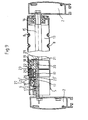
- Fig. 1 shows a section of an inventive Roller conveyor 1. This has 2 held in a frame A large number of rollers 3, which are divided into several sections 4 are divided.
- a circumferential belt 5 is provided for the drive in the area of drive rollers 6 by means of two pressure rollers 7 is pressed against it.
- the drive roller 6 of each section 4 with a drivable and braked Roll 13 detachable This can be driven and braked roller 13 Drive-connected via idler belts 8 with idlers 9, on which piece goods 10 are eligible.
- optical sensors 11 held which detect piece goods 10 and control signals to a control device, not shown send, which will be explained later, clutch and Braking devices of the drivable and brakable rollers 13 controls.
- FIGS. 2 and 3 differs of that according to FIGS. 1 and 2 in that instead of Sensors 11 switching flaps 12 are provided, each one Section 4 are assigned. These flaps 12 are from General cargo 10 actuated and protrude into the path of movement the same.
- the switching flaps 14 act with sensors 11 ' together, the control signals to a not shown Send control.
- An actuated control flap 12 brings (Fig. 4) a sensor 11 'for emitting a signal.
- the belt 5 in Area of each drive roller 6 through the pressure rollers 7 and the drive roller 6 deflected and encloses it in an angle of approx. 20 °.
- the driving and Braked roller 13 provided with two circumferential grooves 14 in which belts 8 are guided around the two neighboring ones Rotate idlers 3. These are with additional straps 8 other idlers of the same section 4 drive connected.
- a ring magnet 18 is in the drivable and brakable roller 13 provided with an inserted coil 19, which is non-rotatable the axis 15 is held.
- the connecting wires of the coil 19 is thereby via an axial and a radial bore 20, 21 guided.
- the ring magnet 18 has one provided with a friction lining 22 Pole face with an annular armature 23rd cooperates.
- the armature 23 is on an axial The direction of the toothing (not shown), which enables axial movement of the armature 23.
- This toothing is in an annular groove 24 with the roller 13 firmly connected annular body 25 incorporated, the one Bearing 17 is rotatably supported on the axis 15.
- this ring body 25 On the outside of this ring body 25 is another Ring groove 26 incorporated, in which another anchor 23 ' an axial toothing axially displaceable, but non-rotatable in the ring body 25 is held.
- This anchor 23 acts with one in the area of the drive roller 6 arranged ring magnets 18 'together, one firmly on the axis 15 held support member 30 in which a coil 19 'is held.
- the coil 19 'of the ring magnet 18' is over Connecting lines 19 'connected in the axial Bore 20 and a radial bore 21 'of the axis 15 run.
- This ring-shaped support part 30 provided with a flange is of a with the roller 6, which is a magnetizable Material is made via a non-magnetizable Gap part 27, e.g. is made of plastic, connected magnetizable flux guide part 31, wherein between the tubular portion of the support member and an air gap remains in the flow guiding part 31.
- the flow guide part 31 is rotatable with a ball bearing 17 supported on the axis 15. Because of the connection of the Flow guide part 31 with the drive roller 6 over the Split part 27, the drive roller 6 via two ball bearings 17th supported.
- Fig. 9 shows a coupled with the drive roller 6 drivable and brakable roller 13.
- the coil 19 'of the Ring magnet 18 'excited whereby the armature 23' to the Pole surfaces of the drive roller 6 and its flux guide part 31 is present. This creates a frictional connection between the Friction lining 22 'and the armature 23' which rotatably with the Ring body 25 of the drivable and brakable roller 13 connected is.
- the coil 19 of the ring magnet 18, which is in the range of drivable and brakable roller 13 is arranged, not excited and thereby released the brake.
- the drivable and braked roller 13 can, depending on the which coil 19, 19 'of the clutch device or brake is excited, driven by the drive roller 6 or with the Axis 15 connected and therefore braked or blocked become.
Landscapes
- Engineering & Computer Science (AREA)
- Mechanical Engineering (AREA)
- Rollers For Roller Conveyors For Transfer (AREA)
- Rolls And Other Rotary Bodies (AREA)
Abstract
Description
Claims (6)
- Rollenförderer mit einer Vielzahl von in einem Rahmen (2) gehaltenen Rollen (3, 6, 13), die mehreren Abschnitten (4) zugeordnet sind und in jedem Abschnitt (4) eine antreibbare und bremsbare Rolle (13) zugeordnet ist, die mit den übrigen Rollen (3) desselben Abschnittes (4) gekuppelt ist, dadurch gekennzeichnet, daß die antreib- und bremsbaren Rollen (13) auf je einer feststehenden Achse (15) gehalten sind, auf der auch eine Antriebsrolle (6) gehalten ist, die über eine elektromechanische Kupplung (18', 23') mit der antreib- und bremsbaren Rolle (13) kuppelbar ist, die ihrerseits mit einer elektromechanischen Bremseinrichtung (18, 23) versehen ist.
- Rollenförderer nach Anspruch 1, dadurch gekennzeichnet, daß die elektromechanische Kupplung einen mit der Achse (15) drehfest verbundenen Ringmagnet (18') aufweist der die Antriebsrolle (6) magnetisiert, die an der der antreib- und bremsbaren Rolle (13) zugekehrten Stirnfläche mit einem Reibbelag (22') versehenen ist, an der ein drehfest mit der antreib- und bremsbaren Rolle (13) verbundener und axial verschiebbar an dieser gehaltener Anker (23') zur Anlage bringbar ist.
- Rollenförderer nach Anspruch 1 oder 2, dadurch gekennzeichnet, daß die Bremseinrichtung einen mit der Achse (15) fest verbundenen Ringmagneten (18) aufweist, dessen Polfläche mit einem Reibbelag (22) versehen ist und mit einem drehfest mit der antreib- und bremsbaren Rolle (13) verbundenen und axial verschiebbar an dieser gehaltenen Anker (23) zusammenwirkt.
- Rollenförderer nach einem der Ansprüche 1 bis 3, dadurch gekennzeichnet, daß die Anker (23, 23') auf einer sich axial erstreckenden Verzahnung gehalten sind.
- Rollenförderer nach einem der Ansprüche 1 bis 4, dadurch gekennzeichnet, daß die Antriebsrollen (6) aller Abschnitte (4) des Rollenförderers (1) über einen umlaufenden Antriebsriemen (5) angetrieben sind.
- Rollenförderer nach einem der Ansprüche 1 bis 5, dadurch gekennzeichnet, daß die antreib- und bremsbare Rolle (13) eines jeden Abschnittes (4) über Riemen (8) mit den übrigen Rollen (3) des betreffenden Abschnittes (4) antriebsverbunden sind.
Priority Applications (1)
| Application Number | Priority Date | Filing Date | Title |
|---|---|---|---|
| AT01890056T ATE249997T1 (de) | 2000-03-06 | 2001-03-02 | Rollenförderer |
Applications Claiming Priority (2)
| Application Number | Priority Date | Filing Date | Title |
|---|---|---|---|
| AT0015000U AT4177U1 (de) | 2000-03-06 | 2000-03-06 | Rollenförderer |
| AT1502000 | 2000-03-06 |
Publications (3)
| Publication Number | Publication Date |
|---|---|
| EP1132321A2 true EP1132321A2 (de) | 2001-09-12 |
| EP1132321A3 EP1132321A3 (de) | 2001-10-04 |
| EP1132321B1 EP1132321B1 (de) | 2003-09-17 |
Family
ID=3482847
Family Applications (1)
| Application Number | Title | Priority Date | Filing Date |
|---|---|---|---|
| EP01890056A Expired - Lifetime EP1132321B1 (de) | 2000-03-06 | 2001-03-02 | Rollenförderer |
Country Status (5)
| Country | Link |
|---|---|
| US (1) | US6471043B2 (de) |
| EP (1) | EP1132321B1 (de) |
| JP (1) | JP2001287820A (de) |
| AT (2) | AT4177U1 (de) |
| ES (1) | ES2206394T3 (de) |
Cited By (5)
| Publication number | Priority date | Publication date | Assignee | Title |
|---|---|---|---|---|
| EP1314663A1 (de) * | 2001-11-27 | 2003-05-28 | Hirschi & Co AG | Staudrucklose Staurollenbahn |
| WO2003106305A1 (de) * | 2002-06-14 | 2003-12-24 | Tgw Transportgeräte Gmbh & Co.Kg. | Rollenanordnung für einen staurollenförderer |
| DE102006043731A1 (de) * | 2006-09-13 | 2008-03-27 | Moll Maschinenbau Gmbh | Staurollenförderer |
| DE102008052903A1 (de) * | 2008-10-23 | 2010-04-29 | Hanns-Peter Mösonef | Rollenfördervorrichtung zum Transportieren von Fördergütern entlang einer Förderstrecke |
| WO2010138984A1 (de) * | 2009-06-03 | 2010-12-09 | Tgw Mechanics Gmbh | Fördervorrichtung zum transport von stückgütern |
Families Citing this family (34)
| Publication number | Priority date | Publication date | Assignee | Title |
|---|---|---|---|---|
| US20040173440A1 (en) * | 2001-06-05 | 2004-09-09 | Harald Mauch | Measurement and detection roller |
| US6615975B2 (en) * | 2001-07-27 | 2003-09-09 | Gebo Convoyeurs Consultants & Systems Inc. | Magnetic coupling assembly for conveyor rollers |
| US6782996B1 (en) * | 2003-02-13 | 2004-08-31 | Rapistan Systems Advertising Corp. | Axle cartridge for conveyor roller |
| US7021456B2 (en) * | 2003-12-05 | 2006-04-04 | Rapistan Systems Advertising Corp. | Conveyor roller with brake |
| US7213701B2 (en) * | 2005-02-03 | 2007-05-08 | Tgw Ermanco Incorporated | Conveyor roller axle stiffener |
| US7477814B2 (en) * | 2005-02-07 | 2009-01-13 | Hewlett-Packard Development Company, L.P. | Method of making a louver device for a light guide screen |
| US7268942B2 (en) * | 2005-02-07 | 2007-09-11 | Hewlett-Packard Development Company, L.P. | Method of making a self-aligned light guide screen |
| US20060176554A1 (en) * | 2005-02-07 | 2006-08-10 | Huei-Pei Kuo | Holographic louver device for a light guide screen |
| US7324278B2 (en) * | 2005-02-07 | 2008-01-29 | Huei-Pei Kuo | Black matrix light guide screen display |
| MX2007002827A (es) * | 2005-03-25 | 2007-04-27 | Yazaki Ind Chem Co Ltd | Transportador por gravedad de rueda o rodillo capaz de controlar el frenado con respecto a un objeto que esta siendo transportado. |
| US7189584B2 (en) * | 2005-04-27 | 2007-03-13 | Hewlett-Packard Development Company, L.P. | Fabrication alignment technique for light guide screen |
| US20060260913A1 (en) * | 2005-05-20 | 2006-11-23 | Wolf Stephen C | Retractable multiple-stage trailer loader/unloader apparatus |
| US7364035B2 (en) | 2005-05-25 | 2008-04-29 | Dematic Corp. | Airless accumulation conveyor |
| US7397984B2 (en) * | 2005-11-01 | 2008-07-08 | Hewlett-Packard Development Company, L.P. | Light guide screen louver device |
| US7535638B2 (en) * | 2005-11-01 | 2009-05-19 | Hewlett-Packard Development Company, L.P. | Fractional coverage louver device for a light guide screen |
| US20070098326A1 (en) * | 2005-11-01 | 2007-05-03 | Kuo Huei P | Light guide screen with louver device |
| US7522339B2 (en) * | 2005-11-21 | 2009-04-21 | Hewlett-Packard Development Company, L.P. | High contrast projection systen |
| US20070131520A1 (en) * | 2005-12-08 | 2007-06-14 | Pepperl + Fuchs, Inc. | Sensor mounting system for a conveyor |
| DE102006048145B4 (de) * | 2006-10-10 | 2014-01-02 | Sick Ag | Rolle für einen Rollenförderer |
| NO327191B1 (no) | 2006-12-05 | 2009-05-04 | Hunton Fiber As | fastkilingsdetektor for en torker til fiberplater eller gipsplater |
| US7503450B2 (en) * | 2007-08-13 | 2009-03-17 | Magstar Technologies, Inc. | Long roller slip conveyor |
| DE102010002039A1 (de) * | 2010-02-17 | 2011-08-18 | Krones Ag, 93073 | Vorrichtung zum Fördern und/oder Stauen von Artikeln |
| AT512115B1 (de) * | 2011-10-27 | 2020-02-15 | Knapp Ag | Kupplungs-brems-einheit für einen stauförderer |
| DE102014003430B4 (de) * | 2014-03-11 | 2020-07-23 | Interroll-Holding Ag | Bremsvorrichtung für einen Rollenförderer, Rollenförder und Verfahren zum Herstellen einer Bremsvorrichtung |
| EP3354604A1 (de) | 2017-01-27 | 2018-08-01 | Schott AG | Rolle, insbesondere für rollenförderer |
| CN110636981B (zh) | 2017-03-08 | 2021-10-26 | 雷勃美国公司 | 包裹分拣传送模块和系统及其方法 |
| US10532894B2 (en) | 2017-03-10 | 2020-01-14 | Regal Beloit America, Inc. | Modular transfer units, systems, and methods |
| WO2019104095A2 (en) | 2017-11-22 | 2019-05-31 | Regal Beloit America, Inc. | Modular sortation units, systems, and methods |
| US10081492B1 (en) * | 2018-03-14 | 2018-09-25 | Hytrol Conveyor Company, Inc. | Zoned accumulation conveyor with electrical actuator and associated method |
| CN112938311B (zh) * | 2019-12-11 | 2022-05-06 | 沈阳新松机器人自动化股份有限公司 | 一种外接动力源多级离合移载贮存辊道装置 |
| CN113071940B (zh) * | 2021-02-23 | 2022-09-20 | 东莞市恒耀超音波设备有限公司 | 一种带刹车机构的用于口罩生产线的间断性传输装置 |
| CN113859905B (zh) * | 2021-09-03 | 2023-07-14 | 中国第一汽车股份有限公司 | 一种限制驱动力的输送线用辊轮 |
| CN114834511B (zh) * | 2022-04-22 | 2023-08-22 | 浙江省特种设备科学研究院 | 一种电梯砝码智能装卸小车 |
| US20250026571A1 (en) * | 2023-07-19 | 2025-01-23 | Intelligrated Headquarters, Llc | Energy reuse systems and methods |
Citations (2)
| Publication number | Priority date | Publication date | Assignee | Title |
|---|---|---|---|---|
| EP0446992B1 (de) | 1990-03-13 | 1994-06-08 | Daifuku Co., Ltd. | Antriebssystem für Rollenförderer |
| EP0586624B1 (de) | 1991-12-23 | 1996-09-25 | Interroll Holding AG | Steuerungssystem für einen stauförderer |
Family Cites Families (12)
| Publication number | Priority date | Publication date | Assignee | Title |
|---|---|---|---|---|
| US3713521A (en) | 1970-10-12 | 1973-01-30 | Takenishi Seisakusho K K | Roller provided with speed controlling mechanism for articles being conveyed on a roller conveyor |
| US3840110A (en) * | 1972-07-24 | 1974-10-08 | Ermanco Inc | Conveyor apparatus |
| US3961700A (en) * | 1973-08-09 | 1976-06-08 | Fleischauer Fred J | Limited torque conveyor construction |
| US4103769A (en) * | 1976-07-06 | 1978-08-01 | Stone Conveyor, Inc. (Entire) | Live roller conveyor |
| FR2510528B1 (fr) * | 1981-07-30 | 1987-04-30 | Jaffre Felicien | Perfectionnements aux transporteurs a rouleaux avec accumulation de charges |
| IT8553173U1 (it) * | 1985-03-26 | 1986-09-26 | O C I Spa | Trasportatore a rulli motorizzati con frizionamento magnetico |
| GB8808290D0 (en) * | 1988-04-08 | 1988-05-11 | Conveyor Units Ltd | Live roller conveyor |
| MY105440A (en) * | 1990-03-08 | 1994-10-31 | Daifuku Kk | Roller conveyor. |
| JP3237355B2 (ja) | 1993-11-29 | 2001-12-10 | 石川島播磨重工業株式会社 | ローラコンベア |
| US5918728A (en) * | 1997-09-16 | 1999-07-06 | Motion Systems, L.C.L.L.C. | Gearless motorized roller with variable frequency controller |
| US6206181B1 (en) * | 1997-09-16 | 2001-03-27 | Motion Systems, L.C. | Gearless motorized conveyor roller |
| US6035999A (en) * | 1998-07-09 | 2000-03-14 | Milwaukee Electronics Corporation | Zoned transport conveyor with automatic zone start-up and shut-down |
-
2000
- 2000-03-06 AT AT0015000U patent/AT4177U1/de not_active IP Right Cessation
-
2001
- 2001-03-02 EP EP01890056A patent/EP1132321B1/de not_active Expired - Lifetime
- 2001-03-02 AT AT01890056T patent/ATE249997T1/de active
- 2001-03-02 ES ES01890056T patent/ES2206394T3/es not_active Expired - Lifetime
- 2001-03-05 US US09/799,453 patent/US6471043B2/en not_active Expired - Fee Related
- 2001-03-06 JP JP2001061275A patent/JP2001287820A/ja active Pending
Patent Citations (2)
| Publication number | Priority date | Publication date | Assignee | Title |
|---|---|---|---|---|
| EP0446992B1 (de) | 1990-03-13 | 1994-06-08 | Daifuku Co., Ltd. | Antriebssystem für Rollenförderer |
| EP0586624B1 (de) | 1991-12-23 | 1996-09-25 | Interroll Holding AG | Steuerungssystem für einen stauförderer |
Non-Patent Citations (2)
| Title |
|---|
| "STAU-ROLLENFOERDERER MIT ELEKTROMAGNETISCHER STAUKUPPLUNG, PASSAGE", STAU-ROLLENFOERDERER MIT ELEKTROMAGNETISCHER STAUKUPPLUNG, XX, XX, 8 March 2000 (2000-03-08), XX, pages 01 - 03, XP002905079 |
| "ZEICHNUNGEN E99/32 ROLLEN ANTRIEBSKUPPLUNG", ANNOUNCEMENT WARNER ELECTRIC, XX, XX, 1 August 1999 (1999-08-01), XX, pages 01 - 05, XP002905080 |
Cited By (6)
| Publication number | Priority date | Publication date | Assignee | Title |
|---|---|---|---|---|
| EP1314663A1 (de) * | 2001-11-27 | 2003-05-28 | Hirschi & Co AG | Staudrucklose Staurollenbahn |
| WO2003106305A1 (de) * | 2002-06-14 | 2003-12-24 | Tgw Transportgeräte Gmbh & Co.Kg. | Rollenanordnung für einen staurollenförderer |
| US7290649B2 (en) | 2002-06-14 | 2007-11-06 | TGW Transportgeräte GmbH | Roller arrangement for an accumulating roller conveyor |
| DE102006043731A1 (de) * | 2006-09-13 | 2008-03-27 | Moll Maschinenbau Gmbh | Staurollenförderer |
| DE102008052903A1 (de) * | 2008-10-23 | 2010-04-29 | Hanns-Peter Mösonef | Rollenfördervorrichtung zum Transportieren von Fördergütern entlang einer Förderstrecke |
| WO2010138984A1 (de) * | 2009-06-03 | 2010-12-09 | Tgw Mechanics Gmbh | Fördervorrichtung zum transport von stückgütern |
Also Published As
| Publication number | Publication date |
|---|---|
| EP1132321B1 (de) | 2003-09-17 |
| EP1132321A3 (de) | 2001-10-04 |
| ATE249997T1 (de) | 2003-10-15 |
| US20020008007A1 (en) | 2002-01-24 |
| US6471043B2 (en) | 2002-10-29 |
| AT4177U1 (de) | 2001-03-26 |
| JP2001287820A (ja) | 2001-10-16 |
| ES2206394T3 (es) | 2004-05-16 |
Similar Documents
| Publication | Publication Date | Title |
|---|---|---|
| EP1132321B1 (de) | Rollenförderer | |
| EP2594510B1 (de) | Fördervorrichtung | |
| EP0810089B1 (de) | Bahneinzugsvorrichtung für eine bahnförmiges Material verarbeitende Maschine, insbesondere eine Rollenrotations-Druckmaschine | |
| DE69707030T2 (de) | Selbsthaltende Kupplungsvorrichtung | |
| EP0531752B1 (de) | Rotierend angetriebene Bremstelleranordnung eines Fadenspanners | |
| EP1538113B1 (de) | Fördereinrichtung | |
| EP2121415B1 (de) | Elektrische servolenkung mit riemenantrieb und berührungsloser riemenspannung | |
| DE69701222T2 (de) | Fadenspannvorrichtung und textilmaschine mit solcher vorrichtung | |
| DE3124540C2 (de) | Programmierbare Bremseinrichtung für eine Zeichenmaschine | |
| DE1244660B (de) | Vorrichtung fuer den Transport von Blaettern, Streifen u. dgl. | |
| EP1567431A1 (de) | Fördersystem für flache nicht-magnetische gegenstände | |
| EP1515904A1 (de) | Transporteinrichtung mit hysteresekupplung | |
| EP1878674B1 (de) | Kettenglied für eine umlaufende Transportkette einer Werkzeugmaschine, sowie Doppelendprofiler mit aus solchen Kettengliedern gebildeten Führungsketten | |
| CH717364B1 (de) | Konstantkraftvorrichtung für eine Schiebetüranlage sowie Schiebetüranlage. | |
| DE102013018272B4 (de) | Verfahren zum Überwachen des Zustandes einer Bremse und Mobilteil mit Rollenlagereinheit | |
| DE19828244A1 (de) | Bandantriebsvorrichtung für Bandumreifungsmaschinen | |
| EP2958785A1 (de) | Transportvorrichtung und verfahren zum betrieb der transportvorrichtung | |
| DE10058199A1 (de) | Vorrichtung zum Führen eines Antriebsmoments | |
| EP0351511A1 (de) | Abzugsvorrichtung für Flachstrickmaschinen | |
| WO1996031334A1 (de) | Vorrichtung zur geschwindigkeitsanpassung von längs einer schienenanordnung bewegbaren wagen | |
| DE102017214284B4 (de) | Aktuator für eine Hinterachslenkung eines Kraftfahrzeuges | |
| WO2017046235A1 (de) | Magnetische trennvorrichtung mit mechanischer aktivierung und deaktivierung | |
| DE19757979A1 (de) | Vorrichtungen zum Antrieb einer Warenbahnleitwalze | |
| DE19835523A1 (de) | Vorrichtung zum linearen Bewegen von Bauteilen | |
| DE8435394U1 (de) | Antriebs-bauelement fuer eine staufoerderbahn |
Legal Events
| Date | Code | Title | Description |
|---|---|---|---|
| PUAI | Public reference made under article 153(3) epc to a published international application that has entered the european phase |
Free format text: ORIGINAL CODE: 0009012 |
|
| PUAL | Search report despatched |
Free format text: ORIGINAL CODE: 0009013 |
|
| AK | Designated contracting states |
Kind code of ref document: A2 Designated state(s): AT BE CH CY DE DK ES FI FR GB GR IE IT LI LU MC NL PT SE TR |
|
| AX | Request for extension of the european patent |
Free format text: AL;LT;LV;MK;RO;SI |
|
| AK | Designated contracting states |
Kind code of ref document: A3 Designated state(s): AT BE CH CY DE DK ES FI FR GB GR IE IT LI LU MC NL PT SE TR |
|
| AX | Request for extension of the european patent |
Free format text: AL;LT;LV;MK;RO;SI |
|
| RIC1 | Information provided on ipc code assigned before grant |
Free format text: 7B 65G 47/26 A, 7B 65G 13/075 B, 7B 65G 13/073 B, 7B 65G 13/071 B, 7B 65G 13/07 B |
|
| TPAD | Observations filed by third parties |
Free format text: ORIGINAL CODE: EPIDOS TIPA |
|
| 17P | Request for examination filed |
Effective date: 20020117 |
|
| AKX | Designation fees paid |
Free format text: AT BE CH CY DE DK ES FI FR GB GR IE IT LI LU MC NL PT SE TR |
|
| GRAH | Despatch of communication of intention to grant a patent |
Free format text: ORIGINAL CODE: EPIDOS IGRA |
|
| GRAS | Grant fee paid |
Free format text: ORIGINAL CODE: EPIDOSNIGR3 |
|
| GRAA | (expected) grant |
Free format text: ORIGINAL CODE: 0009210 |
|
| AK | Designated contracting states |
Kind code of ref document: B1 Designated state(s): AT BE CH CY DE DK ES FI FR GB GR IE IT LI LU MC NL PT SE TR |
|
| PG25 | Lapsed in a contracting state [announced via postgrant information from national office to epo] |
Ref country code: CY Free format text: LAPSE BECAUSE OF FAILURE TO SUBMIT A TRANSLATION OF THE DESCRIPTION OR TO PAY THE FEE WITHIN THE PRESCRIBED TIME-LIMIT Effective date: 20030917 Ref country code: TR Free format text: LAPSE BECAUSE OF FAILURE TO SUBMIT A TRANSLATION OF THE DESCRIPTION OR TO PAY THE FEE WITHIN THE PRESCRIBED TIME-LIMIT Effective date: 20030917 Ref country code: IE Free format text: LAPSE BECAUSE OF FAILURE TO SUBMIT A TRANSLATION OF THE DESCRIPTION OR TO PAY THE FEE WITHIN THE PRESCRIBED TIME-LIMIT Effective date: 20030917 Ref country code: FI Free format text: LAPSE BECAUSE OF FAILURE TO SUBMIT A TRANSLATION OF THE DESCRIPTION OR TO PAY THE FEE WITHIN THE PRESCRIBED TIME-LIMIT Effective date: 20030917 |
|
| REG | Reference to a national code |
Ref country code: GB Ref legal event code: FG4D Free format text: NOT ENGLISH |
|
| REG | Reference to a national code |
Ref country code: CH Ref legal event code: EP Ref country code: SE Ref legal event code: TRGR |
|
| REF | Corresponds to: |
Ref document number: 50100624 Country of ref document: DE Date of ref document: 20031023 Kind code of ref document: P |
|
| REG | Reference to a national code |
Ref country code: IE Ref legal event code: FG4D Free format text: GERMAN |
|
| REG | Reference to a national code |
Ref country code: CH Ref legal event code: NV Representative=s name: PATENTANWAELTE FELDMANN & PARTNER AG |
|
| PG25 | Lapsed in a contracting state [announced via postgrant information from national office to epo] |
Ref country code: DK Free format text: LAPSE BECAUSE OF FAILURE TO SUBMIT A TRANSLATION OF THE DESCRIPTION OR TO PAY THE FEE WITHIN THE PRESCRIBED TIME-LIMIT Effective date: 20031217 Ref country code: GR Free format text: LAPSE BECAUSE OF FAILURE TO SUBMIT A TRANSLATION OF THE DESCRIPTION OR TO PAY THE FEE WITHIN THE PRESCRIBED TIME-LIMIT Effective date: 20031217 |
|
| PG25 | Lapsed in a contracting state [announced via postgrant information from national office to epo] |
Ref country code: PT Free format text: LAPSE BECAUSE OF FAILURE TO SUBMIT A TRANSLATION OF THE DESCRIPTION OR TO PAY THE FEE WITHIN THE PRESCRIBED TIME-LIMIT Effective date: 20031226 |
|
| GBT | Gb: translation of ep patent filed (gb section 77(6)(a)/1977) |
Effective date: 20031204 |
|
| PG25 | Lapsed in a contracting state [announced via postgrant information from national office to epo] |
Ref country code: LU Free format text: LAPSE BECAUSE OF NON-PAYMENT OF DUE FEES Effective date: 20040302 |
|
| PG25 | Lapsed in a contracting state [announced via postgrant information from national office to epo] |
Ref country code: MC Free format text: LAPSE BECAUSE OF NON-PAYMENT OF DUE FEES Effective date: 20040331 |
|
| REG | Reference to a national code |
Ref country code: IE Ref legal event code: FD4D |
|
| REG | Reference to a national code |
Ref country code: ES Ref legal event code: FG2A Ref document number: 2206394 Country of ref document: ES Kind code of ref document: T3 |
|
| ET | Fr: translation filed | ||
| PLBE | No opposition filed within time limit |
Free format text: ORIGINAL CODE: 0009261 |
|
| STAA | Information on the status of an ep patent application or granted ep patent |
Free format text: STATUS: NO OPPOSITION FILED WITHIN TIME LIMIT |
|
| 26N | No opposition filed |
Effective date: 20040618 |
|
| REG | Reference to a national code |
Ref country code: CH Ref legal event code: PFA Owner name: TGW MECHANICS GMBH Free format text: TGW-TRANSPORTGERAETE GMBH#COLLMANNSTRASSE 2#A-4600 WELS (AT) -TRANSFER TO- TGW MECHANICS GMBH#COLLMANNSTRASSE 2#4600 WELS (AT) |
|
| NLT1 | Nl: modifications of names registered in virtue of documents presented to the patent office pursuant to art. 16 a, paragraph 1 |
Owner name: TGW MECHANICS GMBH |
|
| REG | Reference to a national code |
Ref country code: CH Ref legal event code: NV Representative=s name: ABP PATENT NETWORK SWISS GMBH |
|
| REG | Reference to a national code |
Ref country code: FR Ref legal event code: CD |
|
| REG | Reference to a national code |
Ref country code: ES Ref legal event code: PC2A |
|
| PGFP | Annual fee paid to national office [announced via postgrant information from national office to epo] |
Ref country code: BE Payment date: 20120329 Year of fee payment: 12 Ref country code: IT Payment date: 20120228 Year of fee payment: 12 |
|
| PGFP | Annual fee paid to national office [announced via postgrant information from national office to epo] |
Ref country code: NL Payment date: 20120403 Year of fee payment: 12 |
|
| PGFP | Annual fee paid to national office [announced via postgrant information from national office to epo] |
Ref country code: ES Payment date: 20120329 Year of fee payment: 12 |
|
| PGFP | Annual fee paid to national office [announced via postgrant information from national office to epo] |
Ref country code: SE Payment date: 20130226 Year of fee payment: 13 Ref country code: GB Payment date: 20130326 Year of fee payment: 13 Ref country code: CH Payment date: 20130325 Year of fee payment: 13 |
|
| REG | Reference to a national code |
Ref country code: CH Ref legal event code: NV Representative=s name: ABP PATENT NETWORK AG, CH |
|
| PGFP | Annual fee paid to national office [announced via postgrant information from national office to epo] |
Ref country code: FR Payment date: 20130418 Year of fee payment: 13 |
|
| BERE | Be: lapsed |
Owner name: TGW MECHANICS G.M.B.H. Effective date: 20130331 |
|
| REG | Reference to a national code |
Ref country code: NL Ref legal event code: V1 Effective date: 20131001 |
|
| PG25 | Lapsed in a contracting state [announced via postgrant information from national office to epo] |
Ref country code: BE Free format text: LAPSE BECAUSE OF NON-PAYMENT OF DUE FEES Effective date: 20130331 |
|
| PG25 | Lapsed in a contracting state [announced via postgrant information from national office to epo] |
Ref country code: NL Free format text: LAPSE BECAUSE OF NON-PAYMENT OF DUE FEES Effective date: 20131001 |
|
| REG | Reference to a national code |
Ref country code: CH Ref legal event code: PL |
|
| REG | Reference to a national code |
Ref country code: SE Ref legal event code: EUG |
|
| GBPC | Gb: european patent ceased through non-payment of renewal fee |
Effective date: 20140302 |
|
| PG25 | Lapsed in a contracting state [announced via postgrant information from national office to epo] |
Ref country code: SE Free format text: LAPSE BECAUSE OF NON-PAYMENT OF DUE FEES Effective date: 20140303 |
|
| REG | Reference to a national code |
Ref country code: FR Ref legal event code: ST Effective date: 20141128 |
|
| PG25 | Lapsed in a contracting state [announced via postgrant information from national office to epo] |
Ref country code: CH Free format text: LAPSE BECAUSE OF NON-PAYMENT OF DUE FEES Effective date: 20140331 Ref country code: LI Free format text: LAPSE BECAUSE OF NON-PAYMENT OF DUE FEES Effective date: 20140331 Ref country code: GB Free format text: LAPSE BECAUSE OF NON-PAYMENT OF DUE FEES Effective date: 20140302 Ref country code: FR Free format text: LAPSE BECAUSE OF NON-PAYMENT OF DUE FEES Effective date: 20140331 |
|
| PG25 | Lapsed in a contracting state [announced via postgrant information from national office to epo] |
Ref country code: IT Free format text: LAPSE BECAUSE OF NON-PAYMENT OF DUE FEES Effective date: 20140302 |
|
| REG | Reference to a national code |
Ref country code: ES Ref legal event code: FD2A Effective date: 20150424 |
|
| PG25 | Lapsed in a contracting state [announced via postgrant information from national office to epo] |
Ref country code: ES Free format text: LAPSE BECAUSE OF NON-PAYMENT OF DUE FEES Effective date: 20140303 |
|
| PGFP | Annual fee paid to national office [announced via postgrant information from national office to epo] |
Ref country code: DE Payment date: 20160321 Year of fee payment: 16 |
|
| PGFP | Annual fee paid to national office [announced via postgrant information from national office to epo] |
Ref country code: AT Payment date: 20160322 Year of fee payment: 16 |
|
| REG | Reference to a national code |
Ref country code: DE Ref legal event code: R119 Ref document number: 50100624 Country of ref document: DE |
|
| REG | Reference to a national code |
Ref country code: AT Ref legal event code: MM01 Ref document number: 249997 Country of ref document: AT Kind code of ref document: T Effective date: 20170302 |
|
| PG25 | Lapsed in a contracting state [announced via postgrant information from national office to epo] |
Ref country code: DE Free format text: LAPSE BECAUSE OF NON-PAYMENT OF DUE FEES Effective date: 20171003 Ref country code: AT Free format text: LAPSE BECAUSE OF NON-PAYMENT OF DUE FEES Effective date: 20170302 |