EP1133041A1 - Führungsanordnung für Leiterfolie - Google Patents
Führungsanordnung für Leiterfolie Download PDFInfo
- Publication number
- EP1133041A1 EP1133041A1 EP01400632A EP01400632A EP1133041A1 EP 1133041 A1 EP1133041 A1 EP 1133041A1 EP 01400632 A EP01400632 A EP 01400632A EP 01400632 A EP01400632 A EP 01400632A EP 1133041 A1 EP1133041 A1 EP 1133041A1
- Authority
- EP
- European Patent Office
- Prior art keywords
- conductor
- sheet
- pin
- guide
- foldable
- Prior art date
- Legal status (The legal status is an assumption and is not a legal conclusion. Google has not performed a legal analysis and makes no representation as to the accuracy of the status listed.)
- Withdrawn
Links
Images

Classifications
-
- H—ELECTRICITY
- H02—GENERATION; CONVERSION OR DISTRIBUTION OF ELECTRIC POWER
- H02G—INSTALLATION OF ELECTRIC CABLES OR LINES, OR OF COMBINED OPTICAL AND ELECTRIC CABLES OR LINES
- H02G3/00—Installations of electric cables or lines or protective tubing therefor in or on buildings, equivalent structures or vehicles
- H02G3/26—Installations of cables, lines, or separate protective tubing therefor directly on or in walls, ceilings, or floors
Definitions
- the invention relates to a guide device for sheet conductor, especially for sheet cable.
- the object of the present invention is to provide a guiding device for sheet conductor, which allows such a change to be made in a simple manner direction of a sheet conductor.
- a guide device sheet conductor according to the invention is characterized in that it advantageously includes an element two-dimensional and capable of being folded around a fold line area and a return pin sheet conductor around which the conductor can be placed in an inclined position relative to the axis of the pin to achieve a deflection or change of direction, when the pin with the conductor returned by it is arranged in the fold line area.
- the part lying on one side of the fold line area of the foldable element is configured in part for guiding sheet conductor, provided with means for fixing the conductor, and the part on the other side of the fold line area is made as a covering part capable of being folded back on the guide part.
- the guide portion of the foldable member has means for fixing the sheet conductor to it, in its returned position.
- the fixing means are formed by pins positioning in the guide part of the element foldable and the sheet conductor has holes for positioning who are likely to engage around positioning tips.
- the guide part carries on its free surface means, such as fastening clips, for mounting on a support structure.
- the guide part and the covering part of the foldable element includes means by which they are advantageously removably lockable in their folded over position.
- the guide part and the part of overlap are formed by two separate parts, the deflection pin being associated with a part.
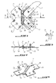
- Figure 1 shows a device for guiding sheet conductors according to the invention.
- These measures has a two-dimensional foldable element 1, which is configured to form a return or change of direction of a conductor in sheet 2, in the example shown of a sheet conductor in form of a ribbon.
- Sheet 2 conductor is returned by the device at an angle of 90 ° and presents, at this end, a cross shape with branch at right angles.
- Foldable item is foldable around a line area folding 3 which forms an angle with the axes of the branches 45 ° and passes through the midpoint of the element foldable.
- Fold line area 3 divides the element foldable in two parts, part 4 for guiding the sheet conductor 2 and a covering part 5 which is foldable on the guide part 4.
- the area of fold line 3 is curved in its cross section and protrudes down from the plane of the element. Above of this concave zone, in the middle of zone 3, extends a return or change pin direction 8 of the sheet.
- This pin extends parallel to zone 3 and to the plane of element 1. It is fixed at one end 9 to element 1 by through a bar 10. The other end of the pin is free. Since the pin 8 extends concentrically with the radius of curvature of the area folding line 3, element 1 is likely to be folded around the pin 8.
- the conductor tape in sheet is arranged, for its change of direction or its return by an angle of 90 °, around the pin 8, which forms with the axis of the conductor tape an angle of 45 °.
- the two branches 11, 12 of the guide part 4 are somewhat wider than the sheet conductor 2 and therefore constitute good bearing faces for the two conductor portions returned 90 °.
- Each bearing face of one of the branches 11, 12 carries a positioning tip 14 which passes through a hole positioning 15 provided in the conductor. The driver 2 is therefore likely to be positioned and fixed on the guide part 4.
- the covering part 5 comprises in each branch 17, 18 a positioning hole 19 in which engages, after folding of the covering part 5 on the guide part 4, the positioning tip 14 arranged symmetrically with respect to the area of the folding line 3, of the guide part branch corresponding. This gives an exact lock of the covering part on the guide part.
- the two parts 4, 5 are locked removably in their folded position.
- the foldable element 1 according to the invention can be fixed on a support structure, such as a body.
- a support structure such as a body.
- a dowel 24 made in one piece with element 1 and likely to be discarded by a small spacing axis 25, in a manner known per se.
- a lug cylindrical 26 is provided on the underside by example of branch 12, as anti-rotation means of the foldable element, as shown in Figure 3.
- Figure 5 shows another embodiment of the folding device according to the invention.
- element 1 consists of two parts, namely a part 28 which constitutes the guiding part of the element 1 and corresponds, from the point of view of its function, to the guide part 4 of the first embodiment, and a second part 29 which is comparable to the part of cover 5.
- the return pin 8 is fixed to the guide part 28.
- the covering part 29 has, on its side facing the pin, a semi-cylindrical element, tubular 31 whose radius is somewhat greater than that of the pin 3.
- the conductor is returned at an angle of 90 °.
- Other deflection angles are however possible. he is sufficient for this purpose to produce the foldable element 1 of so that the two branches of each part 4, 5 have an angle which corresponds to the deflection angle.
Landscapes
- Engineering & Computer Science (AREA)
- Architecture (AREA)
- Civil Engineering (AREA)
- Structural Engineering (AREA)
- Installation Of Indoor Wiring (AREA)
Applications Claiming Priority (2)
| Application Number | Priority Date | Filing Date | Title |
|---|---|---|---|
| FR0003046 | 2000-03-09 | ||
| FR0003046A FR2806221B1 (fr) | 2000-03-09 | 2000-03-09 | Dispositif de guidage pour conducteur en feuille |
Publications (1)
| Publication Number | Publication Date |
|---|---|
| EP1133041A1 true EP1133041A1 (de) | 2001-09-12 |
Family
ID=8847918
Family Applications (1)
| Application Number | Title | Priority Date | Filing Date |
|---|---|---|---|
| EP01400632A Withdrawn EP1133041A1 (de) | 2000-03-09 | 2001-03-09 | Führungsanordnung für Leiterfolie |
Country Status (2)
| Country | Link |
|---|---|
| EP (1) | EP1133041A1 (de) |
| FR (1) | FR2806221B1 (de) |
Citations (3)
| Publication number | Priority date | Publication date | Assignee | Title |
|---|---|---|---|---|
| US4192965A (en) * | 1977-12-29 | 1980-03-11 | Gte Automatic Electric Laboratories Incorporated | Flat ribbon cable retainer |
| US4406916A (en) * | 1981-12-18 | 1983-09-27 | Rockwell International Corporation | Adaptor for routing flat ribbon cables |
| JPH0731043A (ja) * | 1993-07-12 | 1995-01-31 | Yazaki Corp | フラットケーブル用保護具 |
-
2000
- 2000-03-09 FR FR0003046A patent/FR2806221B1/fr not_active Expired - Fee Related
-
2001
- 2001-03-09 EP EP01400632A patent/EP1133041A1/de not_active Withdrawn
Patent Citations (3)
| Publication number | Priority date | Publication date | Assignee | Title |
|---|---|---|---|---|
| US4192965A (en) * | 1977-12-29 | 1980-03-11 | Gte Automatic Electric Laboratories Incorporated | Flat ribbon cable retainer |
| US4406916A (en) * | 1981-12-18 | 1983-09-27 | Rockwell International Corporation | Adaptor for routing flat ribbon cables |
| JPH0731043A (ja) * | 1993-07-12 | 1995-01-31 | Yazaki Corp | フラットケーブル用保護具 |
Non-Patent Citations (1)
| Title |
|---|
| PATENT ABSTRACTS OF JAPAN vol. 1995, no. 04 31 May 1995 (1995-05-31) * |
Also Published As
| Publication number | Publication date |
|---|---|
| FR2806221A1 (fr) | 2001-09-14 |
| FR2806221B1 (fr) | 2004-02-13 |
Similar Documents
| Publication | Publication Date | Title |
|---|---|---|
| FR2911543A1 (fr) | Siege de vehicule automobile a profondeur d'assise reglable | |
| FR2928311A1 (fr) | Dispositif appui-tete electriquement reglable en hauteur d'un siege de vehicule automobile. | |
| EP1800559A1 (de) | Verbindung enthaltend ein Befestigungsgehäuse mit unterer Platte und oberer Platte | |
| EP3561608A1 (de) | Befestigungsleiste eines armbands an einer armbanduhr, die mit zwei einziehbaren drehzapfen ausgestattet ist | |
| FR2906781A1 (fr) | Dispositif motorise de reglage de colonne de direction avec une chaise-support. | |
| EP0035460B1 (de) | Bezeichnungselement für elektrische Drähte | |
| EP1133041A1 (de) | Führungsanordnung für Leiterfolie | |
| EP1226978A1 (de) | Ordnermechanismus | |
| FR2691342A1 (fr) | Table pliante. | |
| EP2963481A1 (de) | Scharnier eines brillengestells | |
| FR2611264A1 (fr) | Detecteur de proximite a tete orientable | |
| FR3070756B1 (fr) | Accessoire d’aide au reglage de l’alignement d’une roue avant d’une bicyclette par rapport a la potence de son guidon | |
| EP0046830B1 (de) | Präzisionszirkel mit gelenkigem Schenkel und steifer Stange | |
| EP0183629A1 (de) | Halter zur drehbaren Befestigung eines Stiftes an den Zirkelschenkeln und Zirkel ausgestattet mit diesem Halter | |
| EP0768548A1 (de) | Gerät zum Erleichtern der Herstellung optischer Faserverbindungen | |
| EP0976507B1 (de) | Zusammenklappbarer Fahrradständer | |
| FR2778705A1 (fr) | Support de barre de toit pour vehicule automobile | |
| FR3053655B1 (fr) | Voilier comportant une structure a flotteur et un mat | |
| FR2683982A1 (fr) | Fermoir portefeuille muni d'une boucle. | |
| FR2515345A1 (fr) | Barometre | |
| FR2773447A1 (fr) | Support de presentation d'une affiche ou similaire | |
| EP4219231A1 (de) | Sitzträgerelement mit verstellbarem abstützelement | |
| FR2743640A1 (fr) | Agencement de fixation d'un bracelet sur une montre | |
| EP3949790A1 (de) | Gürtelschnalle, die sich an mindestens zwei gürtelbreiten anpassen lässt, und gürtel mit einer solchen schnalle | |
| FR2723988A1 (fr) | Element de retenue pourvu d'un moyen de blocage |
Legal Events
| Date | Code | Title | Description |
|---|---|---|---|
| PUAI | Public reference made under article 153(3) epc to a published international application that has entered the european phase |
Free format text: ORIGINAL CODE: 0009012 |
|
| AK | Designated contracting states |
Kind code of ref document: A1 Designated state(s): DE Kind code of ref document: A1 Designated state(s): AT BE CH CY DE DK ES FI FR GB GR IE IT LI LU MC NL PT SE TR |
|
| AX | Request for extension of the european patent |
Free format text: AL;LT;LV;MK;RO;SI |
|
| 17P | Request for examination filed |
Effective date: 20020307 |
|
| AKX | Designation fees paid |
Free format text: AT |
|
| REG | Reference to a national code |
Ref country code: DE Ref legal event code: 8566 |
|
| RBV | Designated contracting states (corrected) |
Designated state(s): DE |
|
| RAP1 | Party data changed (applicant data changed or rights of an application transferred) |
Owner name: LISI AUTOMOTIVE RAPID |
|
| STAA | Information on the status of an ep patent application or granted ep patent |
Free format text: STATUS: THE APPLICATION IS DEEMED TO BE WITHDRAWN |
|
| 18D | Application deemed to be withdrawn |
Effective date: 20081001 |