EP1134069A1 - Hollow structure of fiber-reinforced resin and method of manufacturing the same - Google Patents
Hollow structure of fiber-reinforced resin and method of manufacturing the same Download PDFInfo
- Publication number
- EP1134069A1 EP1134069A1 EP99969691A EP99969691A EP1134069A1 EP 1134069 A1 EP1134069 A1 EP 1134069A1 EP 99969691 A EP99969691 A EP 99969691A EP 99969691 A EP99969691 A EP 99969691A EP 1134069 A1 EP1134069 A1 EP 1134069A1
- Authority
- EP
- European Patent Office
- Prior art keywords
- fibre
- aforesaid
- reinforced plastic
- hollow section
- inner mould
- Prior art date
- Legal status (The legal status is an assumption and is not a legal conclusion. Google has not performed a legal analysis and makes no representation as to the accuracy of the status listed.)
- Withdrawn
Links
- 229920005989 resin Polymers 0.000 title claims description 111
- 239000011347 resin Substances 0.000 title claims description 111
- 238000004519 manufacturing process Methods 0.000 title claims description 42
- 229920002430 Fibre-reinforced plastic Polymers 0.000 claims abstract description 246
- 239000011151 fibre-reinforced plastic Substances 0.000 claims abstract description 246
- 239000000835 fiber Substances 0.000 claims abstract description 133
- 230000003014 reinforcing effect Effects 0.000 claims abstract description 97
- 239000007787 solid Substances 0.000 claims abstract description 30
- 229920003002 synthetic resin Polymers 0.000 claims abstract description 18
- 239000000057 synthetic resin Substances 0.000 claims abstract description 18
- 238000010276 construction Methods 0.000 claims abstract description 13
- 239000000758 substrate Substances 0.000 claims description 113
- 238000000034 method Methods 0.000 claims description 71
- 239000000463 material Substances 0.000 claims description 67
- 238000000465 moulding Methods 0.000 claims description 61
- 239000006260 foam Substances 0.000 claims description 34
- 239000011162 core material Substances 0.000 claims description 28
- 238000009792 diffusion process Methods 0.000 claims description 19
- OKTJSMMVPCPJKN-UHFFFAOYSA-N Carbon Chemical compound [C] OKTJSMMVPCPJKN-UHFFFAOYSA-N 0.000 claims description 16
- 229910052799 carbon Inorganic materials 0.000 claims description 16
- 238000005470 impregnation Methods 0.000 claims description 14
- 238000000071 blow moulding Methods 0.000 claims description 13
- 239000003365 glass fiber Substances 0.000 claims description 13
- 239000003822 epoxy resin Substances 0.000 claims description 12
- 229920000647 polyepoxide Polymers 0.000 claims description 12
- 239000002023 wood Substances 0.000 claims description 12
- 229920003023 plastic Polymers 0.000 claims description 9
- 239000004033 plastic Substances 0.000 claims description 9
- 239000005060 rubber Substances 0.000 claims description 9
- 229920001971 elastomer Polymers 0.000 claims description 8
- 239000012530 fluid Substances 0.000 claims description 8
- 239000013013 elastic material Substances 0.000 claims description 7
- 238000002360 preparation method Methods 0.000 claims description 6
- 229920003169 water-soluble polymer Polymers 0.000 claims description 5
- 229920001903 high density polyethylene Polymers 0.000 claims description 4
- 239000004700 high-density polyethylene Substances 0.000 claims description 4
- 239000002861 polymer material Substances 0.000 claims description 4
- 229920006337 unsaturated polyester resin Polymers 0.000 claims description 4
- 229920001567 vinyl ester resin Polymers 0.000 claims description 4
- 238000005304 joining Methods 0.000 claims description 3
- 229920001568 phenolic resin Polymers 0.000 claims description 3
- 239000005011 phenolic resin Substances 0.000 claims description 3
- 239000011800 void material Substances 0.000 claims description 3
- 239000004760 aramid Substances 0.000 claims description 2
- 229920003235 aromatic polyamide Polymers 0.000 claims description 2
- LNEPOXFFQSENCJ-UHFFFAOYSA-N haloperidol Chemical compound C1CC(O)(C=2C=CC(Cl)=CC=2)CCN1CCCC(=O)C1=CC=C(F)C=C1 LNEPOXFFQSENCJ-UHFFFAOYSA-N 0.000 claims description 2
- 229920001230 polyarylate Polymers 0.000 claims description 2
- 229910052751 metal Inorganic materials 0.000 description 20
- 239000002184 metal Substances 0.000 description 20
- 238000010438 heat treatment Methods 0.000 description 19
- -1 polyethylene terephthalate Polymers 0.000 description 17
- 239000007789 gas Substances 0.000 description 9
- 238000002347 injection Methods 0.000 description 9
- 239000007924 injection Substances 0.000 description 9
- 238000001175 rotational moulding Methods 0.000 description 9
- 230000008878 coupling Effects 0.000 description 8
- 238000010168 coupling process Methods 0.000 description 8
- 238000005859 coupling reaction Methods 0.000 description 8
- 230000001965 increasing effect Effects 0.000 description 8
- 238000009413 insulation Methods 0.000 description 7
- 230000005291 magnetic effect Effects 0.000 description 7
- 230000002708 enhancing effect Effects 0.000 description 6
- 229910000743 fusible alloy Inorganic materials 0.000 description 6
- 230000005484 gravity Effects 0.000 description 6
- 238000012545 processing Methods 0.000 description 6
- XLYOFNOQVPJJNP-UHFFFAOYSA-N water Substances O XLYOFNOQVPJJNP-UHFFFAOYSA-N 0.000 description 6
- 239000004698 Polyethylene Substances 0.000 description 5
- 239000004743 Polypropylene Substances 0.000 description 5
- 238000001816 cooling Methods 0.000 description 5
- 238000005520 cutting process Methods 0.000 description 5
- 239000004744 fabric Substances 0.000 description 5
- 229920000573 polyethylene Polymers 0.000 description 5
- 229920001155 polypropylene Polymers 0.000 description 5
- 230000002787 reinforcement Effects 0.000 description 5
- 229920005992 thermoplastic resin Polymers 0.000 description 5
- 239000001993 wax Substances 0.000 description 5
- PXHVJJICTQNCMI-UHFFFAOYSA-N Nickel Chemical compound [Ni] PXHVJJICTQNCMI-UHFFFAOYSA-N 0.000 description 4
- 239000004809 Teflon Substances 0.000 description 4
- 229920006362 Teflon® Polymers 0.000 description 4
- 230000008901 benefit Effects 0.000 description 4
- 238000004132 cross linking Methods 0.000 description 4
- 230000000694 effects Effects 0.000 description 4
- 238000009730 filament winding Methods 0.000 description 4
- 239000006261 foam material Substances 0.000 description 4
- 239000003562 lightweight material Substances 0.000 description 4
- 239000007788 liquid Substances 0.000 description 4
- 230000033001 locomotion Effects 0.000 description 4
- 239000000696 magnetic material Substances 0.000 description 4
- 239000007769 metal material Substances 0.000 description 4
- 239000002245 particle Substances 0.000 description 4
- 229920000139 polyethylene terephthalate Polymers 0.000 description 4
- 239000005020 polyethylene terephthalate Substances 0.000 description 4
- 229920006327 polystyrene foam Polymers 0.000 description 4
- 239000004800 polyvinyl chloride Substances 0.000 description 4
- 229920000915 polyvinyl chloride Polymers 0.000 description 4
- 239000000843 powder Substances 0.000 description 4
- 230000035882 stress Effects 0.000 description 4
- 239000004593 Epoxy Substances 0.000 description 3
- JOYRKODLDBILNP-UHFFFAOYSA-N Ethyl urethane Chemical compound CCOC(N)=O JOYRKODLDBILNP-UHFFFAOYSA-N 0.000 description 3
- 239000004642 Polyimide Substances 0.000 description 3
- 230000015572 biosynthetic process Effects 0.000 description 3
- 239000011521 glass Substances 0.000 description 3
- 239000010440 gypsum Substances 0.000 description 3
- 229910052602 gypsum Inorganic materials 0.000 description 3
- 230000014759 maintenance of location Effects 0.000 description 3
- 239000011159 matrix material Substances 0.000 description 3
- 238000002844 melting Methods 0.000 description 3
- 230000002093 peripheral effect Effects 0.000 description 3
- ISWSIDIOOBJBQZ-UHFFFAOYSA-N phenol group Chemical group C1(=CC=CC=C1)O ISWSIDIOOBJBQZ-UHFFFAOYSA-N 0.000 description 3
- 229920000728 polyester Polymers 0.000 description 3
- 229920001721 polyimide Polymers 0.000 description 3
- 238000003825 pressing Methods 0.000 description 3
- 229920002379 silicone rubber Polymers 0.000 description 3
- 239000004945 silicone rubber Substances 0.000 description 3
- 239000003351 stiffener Substances 0.000 description 3
- KXGFMDJXCMQABM-UHFFFAOYSA-N 2-methoxy-6-methylphenol Chemical compound [CH]OC1=CC=CC([CH])=C1O KXGFMDJXCMQABM-UHFFFAOYSA-N 0.000 description 2
- CSCPPACGZOOCGX-UHFFFAOYSA-N Acetone Chemical compound CC(C)=O CSCPPACGZOOCGX-UHFFFAOYSA-N 0.000 description 2
- 229910000838 Al alloy Inorganic materials 0.000 description 2
- VTYYLEPIZMXCLO-UHFFFAOYSA-L Calcium carbonate Chemical compound [Ca+2].[O-]C([O-])=O VTYYLEPIZMXCLO-UHFFFAOYSA-L 0.000 description 2
- XEEYBQQBJWHFJM-UHFFFAOYSA-N Iron Chemical compound [Fe] XEEYBQQBJWHFJM-UHFFFAOYSA-N 0.000 description 2
- 229920000877 Melamine resin Polymers 0.000 description 2
- 239000004677 Nylon Substances 0.000 description 2
- 240000007182 Ochroma pyramidale Species 0.000 description 2
- 229920002323 Silicone foam Polymers 0.000 description 2
- XSQUKJJJFZCRTK-UHFFFAOYSA-N Urea Chemical compound NC(N)=O XSQUKJJJFZCRTK-UHFFFAOYSA-N 0.000 description 2
- 230000009471 action Effects 0.000 description 2
- 239000000853 adhesive Substances 0.000 description 2
- 230000001070 adhesive effect Effects 0.000 description 2
- 229910045601 alloy Inorganic materials 0.000 description 2
- 239000000956 alloy Substances 0.000 description 2
- XAGFODPZIPBFFR-UHFFFAOYSA-N aluminium Chemical compound [Al] XAGFODPZIPBFFR-UHFFFAOYSA-N 0.000 description 2
- 239000004202 carbamide Substances 0.000 description 2
- 239000000919 ceramic Substances 0.000 description 2
- 229910010293 ceramic material Inorganic materials 0.000 description 2
- 239000003795 chemical substances by application Substances 0.000 description 2
- 238000004140 cleaning Methods 0.000 description 2
- 239000011248 coating agent Substances 0.000 description 2
- 230000008602 contraction Effects 0.000 description 2
- 230000007797 corrosion Effects 0.000 description 2
- 238000005260 corrosion Methods 0.000 description 2
- 239000004703 cross-linked polyethylene Substances 0.000 description 2
- 229920003020 cross-linked polyethylene Polymers 0.000 description 2
- 239000013078 crystal Substances 0.000 description 2
- 238000013016 damping Methods 0.000 description 2
- 238000013461 design Methods 0.000 description 2
- 238000009826 distribution Methods 0.000 description 2
- 239000003302 ferromagnetic material Substances 0.000 description 2
- 239000000446 fuel Substances 0.000 description 2
- 239000003502 gasoline Substances 0.000 description 2
- 238000001746 injection moulding Methods 0.000 description 2
- 238000007689 inspection Methods 0.000 description 2
- 238000005259 measurement Methods 0.000 description 2
- JDSHMPZPIAZGSV-UHFFFAOYSA-N melamine Chemical compound NC1=NC(N)=NC(N)=N1 JDSHMPZPIAZGSV-UHFFFAOYSA-N 0.000 description 2
- 230000008018 melting Effects 0.000 description 2
- 239000000203 mixture Substances 0.000 description 2
- 229910052759 nickel Inorganic materials 0.000 description 2
- 229920001778 nylon Polymers 0.000 description 2
- 229910000889 permalloy Inorganic materials 0.000 description 2
- 238000005498 polishing Methods 0.000 description 2
- 229920000642 polymer Polymers 0.000 description 2
- 230000008569 process Effects 0.000 description 2
- 239000000047 product Substances 0.000 description 2
- 239000012779 reinforcing material Substances 0.000 description 2
- 238000005096 rolling process Methods 0.000 description 2
- 238000007789 sealing Methods 0.000 description 2
- 239000012056 semi-solid material Substances 0.000 description 2
- 239000013514 silicone foam Substances 0.000 description 2
- 238000005507 spraying Methods 0.000 description 2
- 238000003860 storage Methods 0.000 description 2
- 239000000126 substance Substances 0.000 description 2
- 229920001187 thermosetting polymer Polymers 0.000 description 2
- 239000002759 woven fabric Substances 0.000 description 2
- 230000037303 wrinkles Effects 0.000 description 2
- XMNIXWIUMCBBBL-UHFFFAOYSA-N 2-(2-phenylpropan-2-ylperoxy)propan-2-ylbenzene Chemical compound C=1C=CC=CC=1C(C)(C)OOC(C)(C)C1=CC=CC=C1 XMNIXWIUMCBBBL-UHFFFAOYSA-N 0.000 description 1
- 229920000178 Acrylic resin Polymers 0.000 description 1
- 239000004925 Acrylic resin Substances 0.000 description 1
- ZOXJGFHDIHLPTG-UHFFFAOYSA-N Boron Chemical compound [B] ZOXJGFHDIHLPTG-UHFFFAOYSA-N 0.000 description 1
- 229910000975 Carbon steel Inorganic materials 0.000 description 1
- VYZAMTAEIAYCRO-UHFFFAOYSA-N Chromium Chemical compound [Cr] VYZAMTAEIAYCRO-UHFFFAOYSA-N 0.000 description 1
- PWHULOQIROXLJO-UHFFFAOYSA-N Manganese Chemical compound [Mn] PWHULOQIROXLJO-UHFFFAOYSA-N 0.000 description 1
- 229910001289 Manganese-zinc ferrite Inorganic materials 0.000 description 1
- 229910000861 Mg alloy Inorganic materials 0.000 description 1
- ZOKXTWBITQBERF-UHFFFAOYSA-N Molybdenum Chemical compound [Mo] ZOKXTWBITQBERF-UHFFFAOYSA-N 0.000 description 1
- 229910000990 Ni alloy Inorganic materials 0.000 description 1
- 229910001053 Nickel-zinc ferrite Inorganic materials 0.000 description 1
- 206010067482 No adverse event Diseases 0.000 description 1
- 229930182556 Polyacetal Natural products 0.000 description 1
- 239000004952 Polyamide Substances 0.000 description 1
- 229920000265 Polyparaphenylene Polymers 0.000 description 1
- 239000004793 Polystyrene Substances 0.000 description 1
- 229920005830 Polyurethane Foam Polymers 0.000 description 1
- VYPSYNLAJGMNEJ-UHFFFAOYSA-N Silicium dioxide Chemical compound O=[Si]=O VYPSYNLAJGMNEJ-UHFFFAOYSA-N 0.000 description 1
- UCKMPCXJQFINFW-UHFFFAOYSA-N Sulphide Chemical compound [S-2] UCKMPCXJQFINFW-UHFFFAOYSA-N 0.000 description 1
- 229910001069 Ti alloy Inorganic materials 0.000 description 1
- ATJFFYVFTNAWJD-UHFFFAOYSA-N Tin Chemical compound [Sn] ATJFFYVFTNAWJD-UHFFFAOYSA-N 0.000 description 1
- HCHKCACWOHOZIP-UHFFFAOYSA-N Zinc Chemical compound [Zn] HCHKCACWOHOZIP-UHFFFAOYSA-N 0.000 description 1
- JIYIUPFAJUGHNL-UHFFFAOYSA-N [O--].[O--].[O--].[O--].[O--].[O--].[O--].[O--].[O--].[O--].[O--].[O--].[O--].[O--].[O--].[O--].[O--].[O--].[O--].[O--].[Mn++].[Mn++].[Mn++].[Fe+3].[Fe+3].[Fe+3].[Fe+3].[Fe+3].[Fe+3].[Fe+3].[Fe+3].[Fe+3].[Fe+3].[Zn++].[Zn++] Chemical compound [O--].[O--].[O--].[O--].[O--].[O--].[O--].[O--].[O--].[O--].[O--].[O--].[O--].[O--].[O--].[O--].[O--].[O--].[O--].[O--].[Mn++].[Mn++].[Mn++].[Fe+3].[Fe+3].[Fe+3].[Fe+3].[Fe+3].[Fe+3].[Fe+3].[Fe+3].[Fe+3].[Fe+3].[Zn++].[Zn++] JIYIUPFAJUGHNL-UHFFFAOYSA-N 0.000 description 1
- 238000009825 accumulation Methods 0.000 description 1
- 229920000122 acrylonitrile butadiene styrene Polymers 0.000 description 1
- 239000004411 aluminium Substances 0.000 description 1
- 229910052782 aluminium Inorganic materials 0.000 description 1
- 150000001412 amines Chemical class 0.000 description 1
- 230000001588 bifunctional effect Effects 0.000 description 1
- 229910052797 bismuth Inorganic materials 0.000 description 1
- JCXGWMGPZLAOME-UHFFFAOYSA-N bismuth atom Chemical group [Bi] JCXGWMGPZLAOME-UHFFFAOYSA-N 0.000 description 1
- 210000000746 body region Anatomy 0.000 description 1
- 229910052796 boron Inorganic materials 0.000 description 1
- 238000005219 brazing Methods 0.000 description 1
- 229910052793 cadmium Inorganic materials 0.000 description 1
- BDOSMKKIYDKNTQ-UHFFFAOYSA-N cadmium atom Chemical compound [Cd] BDOSMKKIYDKNTQ-UHFFFAOYSA-N 0.000 description 1
- 229910000019 calcium carbonate Inorganic materials 0.000 description 1
- 239000010962 carbon steel Substances 0.000 description 1
- 230000008859 change Effects 0.000 description 1
- 229910052804 chromium Inorganic materials 0.000 description 1
- 239000011651 chromium Substances 0.000 description 1
- 239000004927 clay Substances 0.000 description 1
- 238000000576 coating method Methods 0.000 description 1
- 239000002131 composite material Substances 0.000 description 1
- 238000002425 crystallisation Methods 0.000 description 1
- 230000008025 crystallization Effects 0.000 description 1
- 230000008030 elimination Effects 0.000 description 1
- 238000003379 elimination reaction Methods 0.000 description 1
- 230000007613 environmental effect Effects 0.000 description 1
- 230000002349 favourable effect Effects 0.000 description 1
- 239000000945 filler Substances 0.000 description 1
- 239000012467 final product Substances 0.000 description 1
- 239000005002 finish coating Substances 0.000 description 1
- 239000004811 fluoropolymer Substances 0.000 description 1
- 229920002313 fluoropolymer Polymers 0.000 description 1
- 239000002828 fuel tank Substances 0.000 description 1
- 239000008187 granular material Substances 0.000 description 1
- 238000007654 immersion Methods 0.000 description 1
- 230000001771 impaired effect Effects 0.000 description 1
- 230000006872 improvement Effects 0.000 description 1
- 239000011261 inert gas Substances 0.000 description 1
- 238000010102 injection blow moulding Methods 0.000 description 1
- 239000012796 inorganic flame retardant Substances 0.000 description 1
- 238000003780 insertion Methods 0.000 description 1
- 230000037431 insertion Effects 0.000 description 1
- 229910052742 iron Inorganic materials 0.000 description 1
- 229920001684 low density polyethylene Polymers 0.000 description 1
- 239000004702 low-density polyethylene Substances 0.000 description 1
- 239000010687 lubricating oil Substances 0.000 description 1
- 238000003754 machining Methods 0.000 description 1
- JMXCGRZQBOMCBD-UHFFFAOYSA-N magnesium;iron(3+);manganese(2+);oxygen(2-) Chemical compound [O-2].[O-2].[O-2].[O-2].[O-2].[Mg+2].[Mn+2].[Fe+3].[Fe+3] JMXCGRZQBOMCBD-UHFFFAOYSA-N 0.000 description 1
- 229910052748 manganese Inorganic materials 0.000 description 1
- 239000011572 manganese Substances 0.000 description 1
- 229920001179 medium density polyethylene Polymers 0.000 description 1
- 239000004701 medium-density polyethylene Substances 0.000 description 1
- 239000000155 melt Substances 0.000 description 1
- 229910052750 molybdenum Inorganic materials 0.000 description 1
- 239000011733 molybdenum Substances 0.000 description 1
- 230000003287 optical effect Effects 0.000 description 1
- 230000003647 oxidation Effects 0.000 description 1
- 238000007254 oxidation reaction Methods 0.000 description 1
- 238000010422 painting Methods 0.000 description 1
- 239000000123 paper Substances 0.000 description 1
- 230000035515 penetration Effects 0.000 description 1
- 150000002978 peroxides Chemical class 0.000 description 1
- 229920001643 poly(ether ketone) Polymers 0.000 description 1
- 229920002647 polyamide Polymers 0.000 description 1
- 229920006122 polyamide resin Polymers 0.000 description 1
- 229920002577 polybenzoxazole Polymers 0.000 description 1
- 229920001748 polybutylene Polymers 0.000 description 1
- 239000004417 polycarbonate Substances 0.000 description 1
- 229920000515 polycarbonate Polymers 0.000 description 1
- 239000004848 polyfunctional curative Substances 0.000 description 1
- 229920000306 polymethylpentene Polymers 0.000 description 1
- 229920006324 polyoxymethylene Polymers 0.000 description 1
- 229920001955 polyphenylene ether Polymers 0.000 description 1
- 229920002223 polystyrene Polymers 0.000 description 1
- 239000011496 polyurethane foam Substances 0.000 description 1
- 238000003908 quality control method Methods 0.000 description 1
- 230000009467 reduction Effects 0.000 description 1
- 238000009745 resin transfer moulding Methods 0.000 description 1
- 238000000926 separation method Methods 0.000 description 1
- 238000009751 slip forming Methods 0.000 description 1
- 239000002904 solvent Substances 0.000 description 1
- 238000001179 sorption measurement Methods 0.000 description 1
- 239000010935 stainless steel Substances 0.000 description 1
- 229910001220 stainless steel Inorganic materials 0.000 description 1
- 229910000815 supermalloy Inorganic materials 0.000 description 1
- 230000008646 thermal stress Effects 0.000 description 1
- 229920001169 thermoplastic Polymers 0.000 description 1
- 229920002725 thermoplastic elastomer Polymers 0.000 description 1
- 239000004416 thermosoftening plastic Substances 0.000 description 1
- 229910052718 tin Inorganic materials 0.000 description 1
- 238000012546 transfer Methods 0.000 description 1
- 238000002604 ultrasonography Methods 0.000 description 1
- 238000005406 washing Methods 0.000 description 1
- 239000013585 weight reducing agent Substances 0.000 description 1
- 238000003466 welding Methods 0.000 description 1
- 238000004804 winding Methods 0.000 description 1
- 229910052725 zinc Inorganic materials 0.000 description 1
- 239000011701 zinc Substances 0.000 description 1
- 229910000859 α-Fe Inorganic materials 0.000 description 1
Images


Classifications
-
- B—PERFORMING OPERATIONS; TRANSPORTING
- B29—WORKING OF PLASTICS; WORKING OF SUBSTANCES IN A PLASTIC STATE IN GENERAL
- B29C—SHAPING OR JOINING OF PLASTICS; SHAPING OF MATERIAL IN A PLASTIC STATE, NOT OTHERWISE PROVIDED FOR; AFTER-TREATMENT OF THE SHAPED PRODUCTS, e.g. REPAIRING
- B29C70/00—Shaping composites, i.e. plastics material comprising reinforcements, fillers or preformed parts, e.g. inserts
- B29C70/04—Shaping composites, i.e. plastics material comprising reinforcements, fillers or preformed parts, e.g. inserts comprising reinforcements only, e.g. self-reinforcing plastics
- B29C70/28—Shaping operations therefor
- B29C70/30—Shaping by lay-up, i.e. applying fibres, tape or broadsheet on a mould, former or core; Shaping by spray-up, i.e. spraying of fibres on a mould, former or core
-
- B—PERFORMING OPERATIONS; TRANSPORTING
- B29—WORKING OF PLASTICS; WORKING OF SUBSTANCES IN A PLASTIC STATE IN GENERAL
- B29C—SHAPING OR JOINING OF PLASTICS; SHAPING OF MATERIAL IN A PLASTIC STATE, NOT OTHERWISE PROVIDED FOR; AFTER-TREATMENT OF THE SHAPED PRODUCTS, e.g. REPAIRING
- B29C70/00—Shaping composites, i.e. plastics material comprising reinforcements, fillers or preformed parts, e.g. inserts
- B29C70/04—Shaping composites, i.e. plastics material comprising reinforcements, fillers or preformed parts, e.g. inserts comprising reinforcements only, e.g. self-reinforcing plastics
- B29C70/28—Shaping operations therefor
- B29C70/54—Component parts, details or accessories; Auxiliary operations, e.g. feeding or storage of prepregs or SMC after impregnation or during ageing
- B29C70/546—Measures for feeding or distributing the matrix material in the reinforcing structure
- B29C70/548—Measures for feeding or distributing the matrix material in the reinforcing structure using distribution constructions, e.g. channels incorporated in or associated with the mould
-
- B—PERFORMING OPERATIONS; TRANSPORTING
- B29—WORKING OF PLASTICS; WORKING OF SUBSTANCES IN A PLASTIC STATE IN GENERAL
- B29C—SHAPING OR JOINING OF PLASTICS; SHAPING OF MATERIAL IN A PLASTIC STATE, NOT OTHERWISE PROVIDED FOR; AFTER-TREATMENT OF THE SHAPED PRODUCTS, e.g. REPAIRING
- B29C70/00—Shaping composites, i.e. plastics material comprising reinforcements, fillers or preformed parts, e.g. inserts
- B29C70/04—Shaping composites, i.e. plastics material comprising reinforcements, fillers or preformed parts, e.g. inserts comprising reinforcements only, e.g. self-reinforcing plastics
- B29C70/06—Fibrous reinforcements only
-
- B—PERFORMING OPERATIONS; TRANSPORTING
- B29—WORKING OF PLASTICS; WORKING OF SUBSTANCES IN A PLASTIC STATE IN GENERAL
- B29C—SHAPING OR JOINING OF PLASTICS; SHAPING OF MATERIAL IN A PLASTIC STATE, NOT OTHERWISE PROVIDED FOR; AFTER-TREATMENT OF THE SHAPED PRODUCTS, e.g. REPAIRING
- B29C70/00—Shaping composites, i.e. plastics material comprising reinforcements, fillers or preformed parts, e.g. inserts
- B29C70/04—Shaping composites, i.e. plastics material comprising reinforcements, fillers or preformed parts, e.g. inserts comprising reinforcements only, e.g. self-reinforcing plastics
- B29C70/28—Shaping operations therefor
- B29C70/40—Shaping or impregnating by compression not applied
- B29C70/42—Shaping or impregnating by compression not applied for producing articles of definite length, i.e. discrete articles
- B29C70/44—Shaping or impregnating by compression not applied for producing articles of definite length, i.e. discrete articles using isostatic pressure, e.g. pressure difference-moulding, vacuum bag-moulding, autoclave-moulding or expanding rubber-moulding
- B29C70/443—Shaping or impregnating by compression not applied for producing articles of definite length, i.e. discrete articles using isostatic pressure, e.g. pressure difference-moulding, vacuum bag-moulding, autoclave-moulding or expanding rubber-moulding and impregnating by vacuum or injection
-
- B—PERFORMING OPERATIONS; TRANSPORTING
- B29—WORKING OF PLASTICS; WORKING OF SUBSTANCES IN A PLASTIC STATE IN GENERAL
- B29C—SHAPING OR JOINING OF PLASTICS; SHAPING OF MATERIAL IN A PLASTIC STATE, NOT OTHERWISE PROVIDED FOR; AFTER-TREATMENT OF THE SHAPED PRODUCTS, e.g. REPAIRING
- B29C70/00—Shaping composites, i.e. plastics material comprising reinforcements, fillers or preformed parts, e.g. inserts
- B29C70/04—Shaping composites, i.e. plastics material comprising reinforcements, fillers or preformed parts, e.g. inserts comprising reinforcements only, e.g. self-reinforcing plastics
- B29C70/28—Shaping operations therefor
- B29C70/40—Shaping or impregnating by compression not applied
- B29C70/42—Shaping or impregnating by compression not applied for producing articles of definite length, i.e. discrete articles
- B29C70/46—Shaping or impregnating by compression not applied for producing articles of definite length, i.e. discrete articles using matched moulds, e.g. for deforming sheet moulding compounds [SMC] or prepregs
- B29C70/48—Shaping or impregnating by compression not applied for producing articles of definite length, i.e. discrete articles using matched moulds, e.g. for deforming sheet moulding compounds [SMC] or prepregs and impregnating the reinforcements in the closed mould, e.g. resin transfer moulding [RTM], e.g. by vacuum
-
- B—PERFORMING OPERATIONS; TRANSPORTING
- B29—WORKING OF PLASTICS; WORKING OF SUBSTANCES IN A PLASTIC STATE IN GENERAL
- B29C—SHAPING OR JOINING OF PLASTICS; SHAPING OF MATERIAL IN A PLASTIC STATE, NOT OTHERWISE PROVIDED FOR; AFTER-TREATMENT OF THE SHAPED PRODUCTS, e.g. REPAIRING
- B29C70/00—Shaping composites, i.e. plastics material comprising reinforcements, fillers or preformed parts, e.g. inserts
- B29C70/68—Shaping composites, i.e. plastics material comprising reinforcements, fillers or preformed parts, e.g. inserts by incorporating or moulding on preformed parts, e.g. inserts or layers, e.g. foam blocks
- B29C70/86—Incorporated in coherent impregnated reinforcing layers, e.g. by winding
- B29C70/865—Incorporated in coherent impregnated reinforcing layers, e.g. by winding completely encapsulated
-
- B—PERFORMING OPERATIONS; TRANSPORTING
- B29—WORKING OF PLASTICS; WORKING OF SUBSTANCES IN A PLASTIC STATE IN GENERAL
- B29L—INDEXING SCHEME ASSOCIATED WITH SUBCLASS B29C, RELATING TO PARTICULAR ARTICLES
- B29L2031/00—Other particular articles
- B29L2031/30—Vehicles, e.g. ships or aircraft, or body parts thereof
- B29L2031/3076—Aircrafts
- B29L2031/3082—Fuselages
Definitions
- the present invention relates to a fibre-reinforced plastic (FRP) structure having a solid of non-revolution shape hollow section (hereinafter a 'fibre-reinforced plastic structure with a hollow section' is referred to as an 'FPR structure with a hollow section' or as a 'hollow FRP structure') such as, for example, an aircraft fuselage, an automobile body or a fluid transportation means, and to an improvement in the method of production thereof.
- FRP fibre-reinforced plastic
- an FRP structure with a hollow section having the shape feature of comparatively small openings compared to the size of the internal cavity and, moreover, which is light in weight and high in strength, so is ideal for use for modes of transport such as the aircraft and automobiles as aforementioned; and to a method of production which enables this structure to be produced simply and with good production efficiency.
- FRP structures have been a focus of attention as structures in cases where a light weight and high strength are demanded, such as for example modes of transport like automobiles and aircraft, containers for the storage or conveyance of gases and liquids, sports goods such as golf club shafts and fishing rods, and building structures such as earthquake-resisting reinforcements.
- hollow FRP structures with comparatively small openings are ideally employed.
- Such hollow FRP structures are normally produced by the so-called filament winding method in which resin-impregnated reinforcing fibre tow is wound onto a rotating liner and then curing carried out.
- hollow FRP structures produced by the filament winding method are limited to solid of revolution shapes where the internal/external shape in the cross-section perpendicular to the axis of rotation is substantially circular in each case. That is to say, only solid of revolution shapes are known as FRP structures with a hollow section where the openings are small compared to the interior width (diameter).
- the ratio of the interior maximum width to the maximum width of the openings is at least 1.1, it is not possible to withdraw the inner mould from the opening, so it is withdrawn for example by cutting the inner mould using a cutter as disclosed in US Patent 3,220,910. In such circumstances, there are limits to such a cutting system when forming a structure of the kind containing ribs.
- moulding techniques have been established by pulltrusion or by the so-called filament winding method in which resin-impregnated reinforcing fibre tow is wound onto a mandrel and then curing performed, but it cannot be said that a moulding technique has yet been established for hollow FRP structures which are of comparatively large size with an overall length of several metres, and which also have openings at the ends or along the length, and where the closed curved surface region is not continuous over the entire length.
- the present invention has as its objectives to resolve the problems of conventional hollow FRP structures as described above, and to provide a solid of non-revolution shape hollow FRP structure having an integral construction, where the FRP characteristics of light weight, high strength and high rigidity can be manifested to a maximum, enabling it to be favourably used for modes of transport and for containers of various kinds; and to a method for the production thereof.
- One embodiment of the fibre-reinforced plastic structure with a hollow section according to the present invention which enables the aforesaid objectives to be realized, is a fibre-reinforced plastic structure with a hollow section which is characterized in that
- Another embodiment of the fibre-reinforced plastic structure with a hollow section according to the present invention is a fibre-reinforced plastic structure with a hollow section which is characterized in that
- Figure 1 is a perspective view showing an example of a hollow FRP structure where the present invention can be applied.
- Figure 2 is a perspective view showing another example of a hollow FRP structure where the present invention can be applied.
- Figure 3 is a perspective view showing still another example of a hollow FRP structure where the present invention can be applied.
- Figure 4 is a perspective view showing still another example of a hollow FRP structure where the present invention can be applied.
- Figure 5 is a perspective view showing still another example of a hollow FRP structure where the present invention can be applied.
- Figure 6 is a schematic structural view showing an example of an FRP moulded body moulding method relating to the present invention.
- Figure 7 is a schematic structural view showing another example of an FRP moulded body moulding method relating to the present invention.
- Figure 8 is a sectional perspective view showing an example of a liner moulding method based on an inner mould with a concave groove, according to the present invention.
- Figure 9 is a schematic structural view showing an example of an FRP moulded body structure relating to the present invention which is different from Figure 1.
- Figure 10 is a perspective view of a hollow FRP structure relating to still another example of the present invention.
- Figure 11 is a perspective view of a hollow FRP structure relating to still another example of the present invention.
- Figure 12 is a perspective view of a hollow FRP structure relating to still another example of the present invention.
- Figure 13 is a schematic structural view showing an example of the method of moulding the still another FRP moulded body relating to the present invention shown in Figure 9.
- Figure 14 is a schematic structural view showing another example of a method of moulding an FRP moulded body relating to the present invention.
- Figure 15 is a schematic structural view showing another example of a method of moulding an FRP moulded body relating to an example of the present invention.
- Figure 16 is a schematic structural view showing still another example of the rib of an FRP moulded body relating to the present invention.
- Figure 17 is a schematic structural view showing still another example of the rib of an FRP moulded body relating to the present invention.
- Figure 18 is a schematic structural view showing still another example of the rib of an FRP moulded body relating to the present invention.
- a hollow section indicates that in a given section of the hollow FRP structure the space formed in the structure interior is enveloped by an outer peripheral portion comprising moulded body and it does not have an opening or passageway through to the outside. Furthermore, a closed space indicates a region over which such a hollow section continues in the lengthwise axial direction. That is to say, it is a region which does not connect with the outside in the circumferential direction.
- this closed space while it is not impossible for it to be a space which does not connect with the outside at all, like the interior of a ball, this is not very practical and, as a rule, it will connect to the outside via regions having openings at the ends of structure in the longitudinal direction or having openings part way along the length thereof, that is to say via regions which do not themselves form closed spaces.
- the longitudinal direction length of such a closed space can vary according to the application and the objectives, so cannot be precisely stipulated but, broadly speaking, it is preferably at least 0.2 m and/or at least 10% of the overall length. Below this numerical range, it may lack practicality due to falling below the lower limit of rigidity for moulding a hollow structure.
- a solid of non-revolution shape denotes any three-dimensional shape which is not a solid of revolution shape.
- a solid of revolution shape essentially denotes a three dimensional shape obtained from the locus when a plane figure shape is rotated, and it includes the sphere, ellipsoid of revolution, cone, cylinder and multi-tapered cylinder, etc.
- shapes which have an axis of symmetry are particularly preferred.
- the structure is not to be restricted to one where each and every section is non-spherical.
- Y X 2 (-0.5 ⁇ X ⁇ 0.5)
- the solid of non-revolution shape FRP structure relating to the present invention comprises a hollow shape, and reference to a hollow shape denotes a shape which essentially possesses an inner space such as a shell shape, tsuzumi drum shape, pipe shape or the like, and the inner space and the space outside are connected by an opening at one or more than one location.
- Such openings can be utilized for the entry and exit of people or hands, the introduction or removal of luggage, or as inlets/outlets for accommodating grain, liquids, gases or the like inside.
- One of the characteristics of the FRP structure with a hollow section of the present invention is that it has a hollow shape with an interior maximum width greater than the maximum width of the openings.
- the maximum width of an opening in the present invention is the maximum value of the distances across the opening and, in terms of dimension, it denotes a large size of at least 1 m.
- the maximum width of the opening corresponds to its diameter
- the maximum width is taken as the maximum value of the straight lines drawn between any two points around the edge of the opening.
- the interior maximum width of the cavity in the main body region in the present invention is the maximum distance across the inner space.
- the direction in which the length is measured is in a plane parallel to the plane of the opening, and the maximum length within this parallel plane is taken as the interior maximum width.
- the openings may also be other than at the two ends.
- the ratio of the interior maximum width to the maximum width of the opening(s) needs to lie within the range 1.1 to 500, and it is preferred that it lie within the range 1.2 to 100. A ratio within the range 1.5 to 50 is still further preferred. If it is smaller than the lower limiting value of this range, the internal space will be insufficient, while if it greater than the upper limiting value then, in the case of a vehicle or container for example, cleaning or washing of the inside will be troublesome.
- sections having a sectional maximum width (the maximum width within a given section) of at least 1.2 times (more preferably at least 1.5 times) the maximum width of the opening extend in the longitudinal direction at least 0.1 m (more preferably at least 0.5 m) and/or that they be at least 5% (more preferably at least 20%) of the total length.
- the magnitude of the sectional maximum width of sections satisfying this condition may be the same or they may be different, for example they may continuously vary. Below the lower limiting value of this range, the interior space will be inadequate and the space for accommodating people may be narrow and uncomfortable. This is a particularly important condition in applications relating to modes of transport such as aircraft and cars.
- the solid of non-revolution shapes in the present invention include those with left/right symmetry and those with top/bottom symmetry. Due to the fact that it is a solid of non-revolution shape, the hollow FRP structure of the present invention can be applied to a variety of applications such as modes of transport and containers of various kinds. Modes of transport include airliners, planes, helicopters and other such flying machines, cars, buses, trucks, motorcycles, bicycles, and passenger ships, sailboats, motor boats, leisure craft and other such vessels, trains, high speed trains and other such rolling stock, and also distribution equipment and the like. As described below, the hollow FRP structure of the present invention is outstanding in its mechanical characteristics, so is suitable for large size structures of several metres and above.
- hollow FRP structure in this invention includes structures where the main constitutional portion is substantially integrally moulded without having joined regions, and also structures composed of a plurality of moulded elements at least one of which is composed of a region forming a closed space and substantially integrally formed.
- the former does not contain parts joined together by means of rivets, bolts and the like, and is substantially integrally formed. Consequently, since there is no cutting of the fibre as in the case where there are parts which are joined together, the strength is high, the wall thickness can be reduced, productivity is high and it is possible to reduce the weight and lower costs. In particular, with a large structure of more than a few metres, the load due to its own weight is high and a limit arises in terms of the size of the structure where parts are joined together but, by integral formation and employing thin walls, larger structures are possible. However, there is no objection to the addition of fitments or the like by means of fastening or bonding.
- the joined parts referred to here are the joints used for structure formation and they do not include the fitment merely of accessories (such as hinges for door attachement, etc) by bolting and the like. Furthermore, it is preferred that the jigs (pins, screws, sheets and blocks, etc) used for accessory coupling which comprise metal or plastic be integrally formed beforehand by insert moulding.
- a section in this main body portion circumferential direction forms a hollow section which constitutes a closed space.
- closed space regions where an integral structure is formed substantially without parts which are joined together, are preferably positioned at the ends of the aforesaid main body portion and/or in the centre thereof.
- the second type of aforesaid structure is the case where a specified hollow FRP structure is constructed by coupling a number of moulded elements by adhesion or by local vacuum moulding, so the moulding of the individual moulded elements is easy and the total structure can be produced cheaply.
- the FRP moulded body which constitutes the chief structural part thereof has a region of hollow section having an integrally moulded structure extending around the entire circumferential direction length and forming a closed space, so at least in this part there is formed a substantially integral structure in which no joined parts are present.
- the greater proportion (preferably 80 vol% and more preferably 90 vol%) of the reinforcing fibre arranged in the circumferential direction within this FRP moulded element is not cut over a length of one lap or more, to give high strength and high stiffness, and to maintain a high strength and rigidity in the FRP moulded body as a whole. Consequently, even in the case of a hollow FRP structure constructed using a plurality of moulded elements, overall a high strength and high modulus are maintained.
- a joined structure comprising a plurality of moulded elements, to form the aforesaid hollow FRP structure as a whole, there may be realized ease of moulding and finishing of the respective moulded elements, and there may be realized ease of coupling of the moulded elements and ease of interior finishing when assembling the hollow FRP structure and producing the final product, so as well as production being simplified it is also possible to lower overall cost.
- the coupling to other moulded elements can be simplified and, furthermore, finishing of the hollow FRP structure interior and internal decorative operations are made extremely easy. Consequently, openings are preferably placed at the ends.
- At least 20%, and more preferably at least 30%, of the total length of a structure used for a mode of transport or of a structure used for a container comprises a hollow FRP structure moulded as an integral structure.
- the entire length of the structure used for a mode of transport or of the structure used for a container will be composed of said hollow FRP structure.
- the inner face of the aforesaid structure has a projecting rib (or ribs) projecting in the radial direction thereof.
- said projecting rib preferably has a frame structure where a core material is present in the interior and this is surrounded by a skin layer containing reinforcing fibre.
- the main body portion is preferably formed with a shell comprising an aforesaid skin layer positioned on the outside and a core material positioned on the inside.
- the inside of the aforesaid core material is formed preferably with a shell comprising fibre reinforced plastic skin layers. It is further preferred that the core material has a rib extending in the radial direction of the structure, and that it comprises a foam and that grooves be formed in the surface thereof.
- the reinforcing fibre used in the fibre-reinforced plastic from which the main body portion is composed can be a known reinforcing fibre such as an inorganic fibre like carbon fibre, glass fibre, SiC type fibre, alumina fibre, boron fibre or metal fibre, or an organic fibre like an aramid fibre, high density polyethylene fibre, PBO (polybenzoxazole fibre), polyarylate fibre or the like, but from the point of view of light weight together with high strength and rigidity, the use of carbon fibre is preferred.
- carbon fibre having an elastic modulus in tension of 200 GPa or more, or carbon fibre of tensile strength 4 GPa or more is preferred.
- the use of carbon fibre of elongation at least 1.5%, and more preferably at least 2.0%, which is outstanding in its impact resistance, is preferred.
- the carbon fibre elastic modulus and strength can be measured based on JIS-R7601, and the elongation can be determined by dividing the strength by the elastic modulus.
- the torsional modulus of elasticity of the reinforcing fibre is preferably within the range 5 to 30 GPa.
- the torsional modulus of elasticity of a fibre can be measured by the method described in JP-A-1-124629.
- the coefficient of thermal expansion of the reinforcing fibre lies in the range -0.1 x 10 -6 to 30 x 10 -6 /°C.
- Glass fibre is preferred from the point of view of insulation, impact resistance and cost.
- Organic fibres are also preferred in cases where insulation is to be provided.
- the hollow FRP structure serves as a mode of transport, it will be subject to frequent outdoor exposure, so there are the effects of rain and UV, and the possibility of being struck by lightning.
- a so-called 'hybrid fibre' where there is jointly employed aforesaid carbon fibre which is outstanding in its environmental resistance and glass fibre or organic fibre which is outstanding in terms of insulation.
- Hybrid types range from those where the different fibre types are interlaced at the yarn/filament level to those where they are distributed in layers or sheets. Furthermore, there are of course included those cases where they are distributed in strand form, as in a covered yarn.
- the hollow FRP structure is a container, tank or a storage vehicle
- the hollow FRP structure there will be stored in the interior thereof grain or other such solids, gasoline or other such liquid, or gases of various kinds, so carbon fibre of low moisture sorption and/or glass fibre of high resistance to gas corrosion is preferred.
- the reinforcing fibre there can be used a unidirectional preform, a woven material, a mat or the like, or combinations of these, but a continuous fibre form is preferred in the terms of the properties of the structure.
- a continuous fibre form is preferred in the terms of the properties of the structure.
- reinforcing fibre which continues along the entire lengthwise direction of the structure.
- Woven material employing aforesaid fibre of elongation at least 2% is preferred because of its outstanding impact resistance.
- glass fibre woven fabric there is little anisotropy and stress concentrations can be mitigated, so this is suitable for regions of stress concentration such as openings, holes, slits and the like.
- a so-called thick reinforcing fibre tow comprising a bundle of 12,000 to 200,000 filaments.
- the volume content of the reinforcing fibre is preferably in the range 35-70%. If the volume content is below this range, there is a tendency for properties of the structure such as strength to be lowered, while, conversely, if the content is too high, difficulties may arise with the resin impregnation, and there are problems such as increased cost.
- the proportion of aforesaid carbon fibre in the reinforcing fibre is preferably from 5 to 100%, by volume content. Now, the volume content can be measured by the method specified in JIS-K7052 or JIS-K7075.
- an epoxy resin unsaturated polyester resin, vinyl ester resin, phenolic resin, modified epoxy resin or other such thermosetting resin, a polyamide resin, polyethylene terephthalate resin, ABS resin, polyetherketone resin, polyphenylene sulphide resin, poly(4-methylpentene-1) resin, polypropylene resin or other such thermoplastic resin, or a rubber material or the like.
- epoxy resins, unsaturated polyester resins and vinyl ester resins with good adhesion to the reinforcing fibre are preferred.
- nylon or other thermoplastic resin or a modified epoxy resin where an epoxy resin is modified with a thermoplastic resin or rubber, is preferred.
- a phenolic resin or a mixture of inorganic flame retardant with an unsaturated polyester resin or vinyl ester resin is preferred.
- the hollow FRP structure of the present invention can be produced on a high-performance low-cost basis by, for example, the resin transfer moulding (RTM) method in which a substrate comprising the aforesaid reinforcing fibre is laid-on or wound-around the outside of an inner mould after which resin is injected into the substrate and curing carried out.
- RTM resin transfer moulding
- the inner mould can be composed of various materials such as wood, plastic, foam, low-melting alloy, water-soluble polymer, wax, glass, gypsum, rubber, ceramic, paper, clay or ice. It will have a shape close to that of the target hollow FRP structure and it has the role of maintaining the three-dimensional configuration of the substrate until the cured or semi-cured state is attained. Hence, it may be removed after the curing or semi-curing of the resin. However, the inner mould may also be left as an integral part of the hollow FRP structure after moulding.
- Moulding is possible using either a hollow or solid inner mould but a hollow inner mould is preferred, not merely because it is lightweight but also because, by applying a surrounding vacuum or applying an internal pressure and causing the inner mould to expand, it is possible to bring about straight aligning of the reinforcing fibre and an enhancement in strength by raising the FRP fibre content.
- the inner mould is light in weight, then it has outstanding handling characteristics such as being moveable at the time of moulding, so it is labour-saving and safe. Again, even in the case where the inner mould is left in the FRP moulded body, it is still possible to ensure a large interior space. Furthermore, less material is used for the inner mould so this is advantageous too economically.
- the substrate and the resin from which the hollow FRP structure is composed comprise the aforedescribed reinforcing fibre and resin, and at the time of the resin injection there can be adopted the so-called vacuum bag method in which the inner mould and the reinforcing fibre substrate are covered over with a bag film, then the pressure in the bag interior reduced and the resin injected.
- a vacuum moulding method in which, with a covering material interposed between the inner mould and the reinforcing fibre substrate, pressure-reduction is effected between the inner mould and an outer mould described below, after which the resin is injected.
- said covering material is preferably an elastic material.
- the covering material may be an elastic material comprising rubber or other polymer material separately produced from the inner mould or it may also be an elastic material formed as a coating or the like on the outer face of a splittable or integrally-formed inner mould.
- the elastic material need not merely secure a vacuum between it and the outer mould, but can also suppress resin accumulation in gaps between the substrate and inner mould caused by the slight discrepancies in inner mould distortion which readily arise at the corners of the projecting regions, such as ribs, formed on the inner mould, or it can facilitate mould release or can act to reduce distortion or movement of inserts such as fitments.
- the preferred thickness of the covering material is about 0.1 to 2 mm.
- the elongation of the elastic material is preferably at least 3%.
- the aforesaid covering material may also be used as a medium having the function of lowering the flow resistance of the resin and enhancing its diffusion efficiency (that is to say, as a resin diffusion medium), and for example if there is arranged a plastic net, mesh, mat or the like, the resin diffusion rate is increased, there is smoother flow into fine regions, and the moulding characteristics are markedly improved.
- grooves of depth in the range from a few millimetres to a few centimetres be formed in the inner mould surface. Specifically, it is preferred that the depth thereof lies in the range from 1 to 50 mm (more preferably 3 mm to 1 cm) and that the spacing of the grooves is about 5 to 900 mm (more preferably 10 to 100 mm). Moreover, the grooves may mutually cross or they may be formed in parallel. Such grooves form channels in which the resin flows at the time of the resin injection. They also form passageways for the air inside the bag to travel along when a vacuum is applied, so that air from within the substrate is readily eliminated and the resin passes everywhere throughout the substrate (to envelop the individual reinforcing fibres). Thus, mouldings are obtained which have few voids, possess outstanding mechanical properties and are of high reliability.
- the amount of voids in the hollow FRP structure is preferably no more than 2% by volume and more preferably no more than 1.5%.
- the void content can be determined from the specific gravity but, as an alternative method, any section of the moulded body is abraded using sandpaper (fine material of grade #1000 or better) and buffing (particle size of the polishing powder no more than 5 ⁇ m) until the fibre is exposed, and then the area of voids determined using an optical microscope at a magnification of 500. In such circumstances, a more accurate measurement of the void content can be made by taking an observation area of at least 50 mm 2 .
- an aforesaid rib-shaped liner in the interior of the hollow FRP structure.
- a liner is extremely effective for enhancing the rigidity.
- the liner there can be used a reinforcing fibre-containing polymer or ceramic sprayed material, a gel coat, a phenolic or other face panel, a titanium alloy, aluminium alloy, magnesium alloy or other light metal sheet or rod material, various types of foam material, and combinations of two or more of these materials.
- the liner does not need to be present over the entire inner face of the hollow FRP structure, and it may be provided locally, for example around openings or in regions which include the centre of a broad curved face or flat face portion.
- the liner may be, for example, a FRP or metal stiffener, spar, stringer or the like which is separately moulded from the hollow FRP structure, or it may be a stiffener, spar, stringer or the like integrally-moulded along with the hollow FRP structure.
- stiffener, spar and stringer refer to, for example, a girder, rib, framework, frame or reinforcing material.
- the cross-sectional shape of the liner may be round, C-shaped, hollow square-shaped, hat shaped, T-shaped, I-shaped, Z-shaped, S-shaped or the like.
- the C-shape and hat-shape sections, which are hollow, are preferred in terms of enhancing rigidity, and furthermore the introduction of a lightweight material such as a foam into the hollow region is further preferred (see Figure 8).
- the liner has a cavity, this is preferred in terms of weight reduction, and it can also be advantageously employed in some applications, such as for the circulation of a fluid for heating/cooling, as flow channels for fuel, lubricating oil or the like, or as passages for wiring or the like.
- a fluid for heating/cooling as flow channels for fuel, lubricating oil or the like, or as passages for wiring or the like.
- the lightweight material are urethane foam, polystyrene foam, polyethylene foam, polypropylene foam, phenolic foam, urea foam, polyvinyl chloride foam, silicone foam, epoxy foam, polyimide foam, polyester foam, melamine foam and other such lightweight foams, and wood such as balsa wood or the like, where these have an apparent specific gravity in the range about 0.02 to 0.9.
- polyimide foam is preferred in structures for modes of transport, where fire retardance is strictly demanded.
- the torsional rigidity of wood such as balsa wood is high and it does not readily buckle under shear, so it is also preferred.
- the aforesaid groove in the lightweight material provided for resin flow may also serve as the groove 81 shown in Figure 8 in the resin-filled state, or it may be different therefrom.
- the application of pressure to the outside of the substrate material by placing in an outer mould which divides into two or more parts is also preferred.
- the outer mould may be in direct contact, or in indirect contact via a buffer layer such as a bag film, rubber or air cushion.
- the most preferred pressure lies in the range from 0.5 kg/cm 2 to 20 kg/cm 2 .
- a vacuum port for pressure reduction and a port for resin injection in the outer mould or inner mould are provided. If provided in the outer mould, the usability is excellent, while if provided in the inner mould there is the feature that no marks are left in the outer face of the moulded material. Thus, appropriate selection may be made. Again, there is also the possibility of providing these ports other than in the outer mould or inner mould by design of the mould or jig structure.
- the material for the outer mould in the case where heat resistance or high accuracy is required, a metal material or ceramic material is preferred, whereas in the case where lightness of weight or economy are necessary, an FRP or wood material is preferred.
- the outer mould is dividable into two or more parts, with more parts being used the more complex the shape, such as when the inner mould has projecting regions, and this facilitates removal from the outer mould. Taking into account a balance in terms of cost, it is most preferred that it can be divided into about 3 to 6 parts.
- Methods for heating the outer mould include direct heating methods such as inserting a heating element into the outer mould or using a flow of heating medium, and indirect heating methods such as with an infrared heater or other such heater, or piping through which a heating fluid circulates, provided in the vicinity of the exterior surface of the outer mould.
- direct heating is preferred in that the resin curing time can be reduced and the moulding cycle shortened. Again, it is also effective in that it is possible to increase the maximum attainable temperature.
- Indirect heating is useful in cases where it is necessary to simplify or lighten the outer mould. Indirect heating is suitable when the thickness of the outer mould lies in the range about 2 to 300 mm.
- a covering layer is integrally formed at the outer face of the FRP.
- a gel coat be applied to the inside of the outer mould, so there is integral moulding of the gel coat with the FRP.
- Any known gel coat can be used such as an epoxy gel coat, polystyrene gel coat or urethane gel coat, but it is further preferred that there be used a resin of the same type as the FRP or a material of similar coefficient of linear expansion. This is because thermal stress produced by temperature differences may cause separation to occur.
- the gel coat is not a structural member so it is preferred that its thickness lies in the range from 0.1 to a few mm. Within this range, the lightness is not impaired and the surface smoothness is maintained.
- an outwardly-directed force in the inner mould for example to apply an internal pressure.
- the preferred pressure lies within the range 0.5 to 10 kg/cm 2 , with the range 1.0 to 5 kg/cm 2 G further preferred,
- the internal pressure may be applied by means of a gas such as compressed air, or, where required, there may be used water or other such non-compressible pressurizing medium. Appropriate control of the internal pressure during the production process is also effective.
- control is possible such that, when arranging the substrate, priority is given to workability and so the pressure is lowered, and then thereafter the pressure is raised so that the inner mould expands, causing the slack in the reinforcing fibre of the substrate to be eliminated.
- the inner mould is a magnetic substance or contains a magnet
- Typical examples of magnetic substances are ferrite, permalloy, nickel alloy, iron and other such metal materials, of which super-permalloy, supermalloy and other such ferromagnetic materials containing molybdenum, manganese and chromium, and ferromagnetic materials such as manganese-zinc ferrite, nickel-zinc ferrite and magnesium-manganese ferrite are preferred, in that a large force can be generated when the inner mould is made to deform.
- the internal pressure may be directly applied to the inner mould but in the case of a dividable inner mould assembled from block-shaped and/or sheet-shaped materials comprising wood or metal for example, a balloon may be inserted into the interior of the inner mould and this then made to expand.
- a release material be inserted between the FRP and outer mould.
- the release material there are "Teflon” film and "Teflon” rubber or silicone rubber.
- the outer shape of the inner mould will be roughly the same as the hollow FRP structure, but in the case of a semi-solid such as silicone rubber the inner mould does not necessarily need to resemble the target structure. It can have a cheaper and more simple form, and the shape of the target moulded body can then be imparted to the semi-solid.
- a semi-solid material Since the level of distortion of a semi-solid material is high, even when it has a rather complex shape with, for example, projections or the like, it can be removed without damaging the structure. Moreover, a semi-solid material can also be reused after carrying out the release treatment. If, when arranging the substrate on the outer face of the inner mould the reinforcing fibre of the substrate extends for two or more laps of the circumference of the hollow inner mould, the pressure from the hollow inner mould is concentrated only in the reinforcing fibre and it is difficult to uniformly apply pressure to the structure as a whole.
- the hollow inner mould is made to expand radially and, furthermore, the reinforcing fibre also made to move a little to produce a slack-free state, so if the fibre extends for two or more laps then this movement will be impeded.
- the FRP structure may not be moulded to the desired shape and dimensions, and the escape of bubbles or the diffusion of resin may be inadequate, so that the characteristics of the FRP structure are not fully manifested. Consequently, it is preferred that arrangement of the substrate be carried out such that reinforcing fibre does not extend continuously for two or more circuits of the hollow inner mould, that is to say it does not extend continuously over two or laps of the circumference of the interior space of the hollow FRP structure.
- reference here to the arrangement being carried out such that it does not extend continuously for two or more laps means that at least 80 vol% (more preferably 90 vol% and still more preferably 95 vol%) of the reinforcing fibre in the FRP does not extend continuously for two or more laps, and it is not intended to exclude the case where even one reinforcing fibre extends continuously over two or more laps.
- the hollow FRP structure preferably has parts which are integrally moulded over the entire circumferential direction length.
- Such parts integrally moulded over the entire circumferential direction length need not necessarily be formed within a single section and, for example, they may be formed as parts extending over the entire circumferential direction length while zigzagging or meandering in the circumferential direction.
- any method may be employed for the arranging of the substrate, but since the hollow FRP structure of the present invention has a three-dimensional form the positions of the substrate are staggered during the arrangement operation and in order to prevent slippage there is preferably used a substrate retainer.
- substrate retainer there can be used various types of substrate retainer, such as the hook type having for example a C-shape, or the adhesive or tacky adhesive type.
- the hook type this may be made of metal, resin or FRP for example, and when a suitable resin is employed this can be caused to melt as a result of the heating in the FRP structure moulding process, so there are no adverse effects on the characteristics of the FRP structure.
- a substrate retainer made of metal there can be used ultrasound, X-rays or a metal detector to determine whether or not the appropriate number of retainers has been used or to assess whether or not the position of the retainers has slipped during the moulding.
- a resin can also be used and in such circumstances selection may also be such that it does not melt-away following moulding.
- the resin there may be used matrix resin mixed with a solvent such as acetone to reduce the viscosity, and by spraying this onto the reinforcing fibre substrate with a sprayer, the substrates can be temporarily held together, or the substrate can be temporarily fixed to the mould by the tackiness thereof.
- a method using magnetic force has high production efficiency and is preferred in terms of the environment at the production site.
- a method of securing the substrate and the inner mould by magnetic force between a magnetic material such as a metal provided on the inner face side of the hollow inner mould and metal or a magnet arranged on the outer face of the substrate or the method of securing and fixing the substrate to the inner mould by a magnetic force acting between a magnetic material and/or magnet mixed with or inserted into the interior of the hollow or solid inner mould and a magnetic material and/or magnet arranged outside of the substrate.
- the magnetic material or magnet may have any shape but if it has a strip shape then it is possible to secure the substrate loosely over a comparatively broad range, while with a spot-shape local firm retention is possible. With a frame shape, retention is possible in the shape of the frame.
- the inner mould may be extracted after the moulding, or part or all may also be left as part of the structure. Where the inner mould is hollow, and it is to be removed then it can be readily stripped away from the inside, while if it is not to be removed but left, then the interior space of the structure is maintained in the desired shape. Again, a release treatment can be performed at locations where the inner mould is to be stripped away, or a release film such as "Teflon" may be inserted.
- the inner mould used for moulding the hollow FRP structure of the present invention can be produced by various hollow structure production methods but, of these, it is possible by the so-called blow moulding method to produce comparatively large and quite complex shapes efficiently to a desired thickness.
- blow moulding method By providing rib-shapes in the outer mould used for the blow moulding, it is possible to form grooves in the outer face of the inner mould easily.
- the material of the inner mould is not particularly restricted but a thermoplastic resin suitable for blow moulding such as polyethylene terephthalate, polyethylene, polyvinyl chloride, polyphenylene ether, polypropylene or the like is preferred.
- a thermoplastic resin suitable for blow moulding such as polyethylene terephthalate, polyethylene, polyvinyl chloride, polyphenylene ether, polypropylene or the like is preferred.
- polypropylene containing glass fibre is preferred in that the rigidity of the inner mould can be markedly raised, so layering of the substrate and handling of the inner mould are facilitated.
- the appropriate content of glass fibre is from 1% to 30%, and the glass fibre length is about 0.1 to 100 mm by weight average.
- a material which is highly elastic, such as rubber is preferred.
- at least the surface is preferably a material with outstanding release properties such as a silicone rubber.
- the heat resistance of the inner mould be higher than said resin curing temperature or provisional curing temperature.
- the heat resistance temperature be at least 5°C higher than the resin curing temperature or the provisional curing temperature, in that it is possible to suppress distortion of the inner mould during the resin curing or provisional curing and the dimensional accuracy of the structure can be ensured.
- the heat resistance of the inner mould is defined by the Vicat softening point measured in accordance with JIS-K6760.
- the hollow FRP structure of the present invention can be produced via at least the following stages (A) to (D) in turn.
- stage in which the entire body is cured within the temperature range 50 to 200°C and integral moulding effected.
- the hollow FRP structure of the present invention can also be produced via at least the following stages (A) to (E) in turn.
- At least a part of the outer face of the inner mould be covered with a sheet-shaped covering material, and on top of this there is arranged the substrate comprising reinforcing fibre in part or in total, after which covering is performed from the outer periphery thereof with the outer mould, and then the region between said outer mould and inner mould reduced in pressure, and synthetic resin injected in a state with the aforesaid covering material expanded or caused to move in the direction of the outer mould and, by allowing said resin to diffuse through the reinforcing fibre substrate in the face direction, the interior of the reinforcing fibre substrate is impregnated with the resin.
- an inner mould comprising an elastic material, that the interior of the inner mould be pressured with a fluid and said inner mould caused to expand in the direction of the outer mould, and that the fluid used for the internal pressurizing of the inner mould in such circumstances be compressed air, the pressure of which preferably lies in the range 0.05 to 1.0 MPa (0.5 to 10 kgG/cm 2 ) and more preferably 0.1 to 0.5 MPa.
- a resin diffusion medium which enables resin to diffuse into the covering material, and that this medium be a reticulate material.
- the inner mould a plastic, rubber material, water-soluble polymer material or wood is preferably employed, and it is preferred that it be moulded in the form of a hollow body by the blow moulding method.
- a substrate arrangement stage (B) when arranging the substrate comprising reinforcing fibre, it is preferred that there be used, between substrates and/or between substrate and inner mould a substrate retainer which secures the substrate. It is preferred that moulded elements be integrally coupled by joining together by means of a local moulding method.
- moulded elements When producing a fibre-reinforced plastic structure composed of a plurality of moulded elements, at least one of which moulded elements has a solid of non-revolution shape section and is provided with at least one opening and a main body portion having a cavity in the interior, at the time of the coupling together of these moulded elements said moulded elements can be mutually joined together by arranging reinforcing fibre to straddle the joint regions between the moulded bodies, and then the joint regions are locally covered with a bag from above the reinforcing fibre, after which the pressure inside the bag is lowered and resin introduced, so that impregnation is effected.
- Integrally-formed openings lead to a considerable lowering of costs, since there is no need to carry out after-processing such as cutting away moulded materials, and therefore there is a saving of materials and a saving of processing time. Again, since no machining is performed, there are no aforesaid inherent problems at the ends and reliability is outstanding. In cases where a large opening is required, it is preferred that more reinforcing fibre be arranged around the opening and that the wall thickness too be made greater than that in other parts.
- wood, plastic, lightweight foam, low melting alloy, water-soluble polymer, glass, gypsum and wax can be cited as preferred materials for an inner mould of the kind described above.
- wood is preferred in that it is easily processed, withstands repeated use, and is light and heat resistant.
- wood which has been machined in the form of small rods, sheets, keys or blocks, which are assembled as 'building blocks' so that the outer shape of the inner mould is the same as that of the target structure.
- the aforesaid processing to provide grooves can readily be carried out.
- thermoplastic resin which is suitable for injection moulding, blow moulding, rotational moulding or vacuum moulding is most preferred.
- the inner mould can be moulded to a shape essentially identical to that of the target FRP structure, and with fine grooves in the inner mould outer surface, at low cost.
- blow moulding the inner mould can be moulded at high productivity and low cost.
- the inner mould thickness lies within the range about 0.5 to 20 mm, the inner mould may be left behind in the moulded article.
- a thin inner mould possesses transparency, and it is possible to check the state of resin impregnation of the FRP without removing the inner mould from the interior of the moulded article. Now, removal can be carried out by stripping or the like. In the case where a water-soluble polymer (for example water-soluble nylon) is used, it is possible to remove the inner mould by immersion in water for example.
- a water-soluble polymer for example water-soluble nylon
- the draw ratio preferably lies in the range 1 : 1 to 1 : 3.
- Preferred resins in the case of rotational moulding are high density polyethylene, medium density polyethylene, low density polyethylene, crosslinked polyethylene, PVC, polyethylene terephthalate, polyamide, polycarbonate, acrylic resin, polybutylene, fluoropolymer, polyester, polyacetal, epoxy resin and the like.
- the powder size lies in the range from 20 to 100 mesh, in that the inner mould thickness is uniform and the internal structure homogeneous, changes in shape at the time of heating or when pressure is applied are uniform, and the accuracy of the structure is enhanced.
- Polyethylene is especially preferred in cases where heat resistance and release properties are required.
- crosslinked polyethylene is extremely outstanding in its heat resistance and its stress corrosion resistance, so is preferred.
- crosslinking with peroxides is preferred from the point of view of heat resistance, rigidity and impact resistance and, in particular, it is preferred that said crosslinking be conducted to a degree of crosslinking of at least 60% by means of dicumyl peroxide, in that the elongation is markedly raised and the impact resistance of the inner mould increased, and it is possible to suppress impact damage to the inner mould during the production process. This is because, in the case where an internal pressure is applied to the inner mould there is the possibility of gas leaks or the like arising at the time of pressurization as a result of damage caused by inadvertent impact during the production process.
- Rotational moulding when compared to injection moulding or blow moulding, is a low-pressure moulding method. Equipment costs are low and it is excellent economically. Furthermore, there is the feature that by using at least biaxial rotational moulding equipment it is possible to simultaneously produce inner moulds of different shapes, and so this can be applied to cases of the production of integral structures using different inner moulds. Again, it is possible to produce large size moulds when compared to blow moulding, and so it is more preferred the larger the size of the structure. Moreover, there are no residual stresses so levels of shape change when the inner mould is heated are stable, and thus this method is suitable in cases where high accuracy is demanded of the structure.
- the rotational ratio of the main shaft to the ancillary shaft be between 0.8 and 7. It is preferred that the rate of rotation of the main shaft lies in the range 3 to 40 rpm, for obtaining an inner mould of uniform thickness. Furthermore, in order to reduce residual thermal strain in the inner mould, to achieve uniform expansion when the inner mould is heated and to enhance the accuracy of the structure, it is preferred that the mould used for the rotational moulding be an electroformed mould or a cast mould.
- the preferred materials for the mould are aluminium alloys, nickel, carbon steel and stainless steel, which are excellent in their electro-thermal properties. Of these, aluminium and nickel are light and require little power for rotation, so are preferred.
- the cooling rate has a direct influence on the contraction of the inner mould, dimensional accuracy such as deformation strain, and the uniformity of the structure such as the degree of crystallization and the crystal size distribution, so a suitable cooling rate is required. If the cooling is too slow, the density increases due to crystal growth and the mould shrinkage is increased. Moulding strains can be reduced by applying a gas pressure to the mould interior in the cooling stage. Again, if the interior is flushed out with an inert gas, oxidation can be almost completely prevented, so this is preferred.
- a lightweight foam means a lightweight foam material such as a urethane foam, polystyrene foam, polyethylene foam, polypropylene foam, phenolic foam, urea foam, polyvinyl chloride foam, silicone foam, epoxy foam, polyimide foam, polyester foam or melamine foam, of apparent specific gravity about 0.02 to 0.9.
- a foam material such as a urethane foam, polystyrene foam, polyethylene foam, polypropylene foam, phenolic foam, urea foam, polyvinyl chloride foam, silicone foam, epoxy foam, polyimide foam, polyester foam or melamine foam, of apparent specific gravity about 0.02 to 0.9.
- a water pressure in the range about 7 to 20 kg/cm 2 has little possibility of damaging the FRP so this is preferred.
- this need not necessarily be removed after moulding and indeed it is preferred that the foam be left in parts of the structure where thermal insulation is required, sound proofing is required, damping of vibration is required or impact resistance is required (that is to say, the inner mould can be left as a member equivalent to a liner).
- the material and thickness, etc, of the inner mould be selected beforehand so as to achieve the desired thermal insulation, noise insulation, vibrational properties and impact characteristics.
- a reinforcing material such as a filler like calcium carbonate or silica particles
- a low-melting alloy inner mould can be re-used, so is preferred. Alloys of melting point about 40-200°C in which the chief component is bismuth, lead, tin, zinc and cadmium have a specific gravity of about 7 to 11.
- the FRP resin is a thermosetting resin
- the inner mould it is necessary for the inner mould to be heat resistant, and from the point of view of raising the curing temperature of the FRP it is preferred that the melting point of the low-melting alloy be in the range 80-200°C. Furthermore, taking into account operational safety, it is most preferred that it be within the range 80-140°C.
- An inner mould made of glass is difficult to mould but it is transparent so, just as in the case of the aforesaid plastic inner mould it is advantageous in terms of checking the moulded state of the FRP.
- a gypsum inner mould has the advantages of being cheap and having extremely high heat resistance.
- a wax inner mould can be removed by heating, in the same way as a low-melting alloy.
- natural waxes are environmentally friendly. Again, the shape of a wax can be readily changed or corrected.
- the hollow FRP structure relating to the present invention is a hollow FRP structure having an interior maximum width (of at least 0.5 m) which is greater than the maximum width of the openings, and the shape of structure is that of a solid of non-revolution, or alternatively it has at least three openings, and, specifically, it can be applied for example to the following kinds of hollow structures.
- Figures 1 to 6 show specific practical examples.
- Figure 1 is an image model for facilitating understanding of the present invention and shows a large hollow FRP structure 1 which can be employed for a mode of transport (for example for a small-size plane or motor car) or the like, and which is an integral structure having openings 2 , 3 at the two ends and openings 4 for windows or doors in the centre. Furthermore, it has an interior maximum width which is at least two times the maximum width of the openings 2, 3, and two openings are provided other than at the ends.
- a rib within which a core material is provided as illustrated in Figure 8, and regions other than this are essentially composed of a skin layer and a sandwich layer as in Figure 18.
- it is a comparatively large-size hollow structure of length at least 2 m and interior maximum width at least 1 m.
- Figure 2 shows a hollow FRP structure 11 for constructing the monocoque body for a motor vehicle having openings 12 to 17 (rear window 16 is not illustrated).
- a hollow FRP structure 11 forming an essentially integral structure moulded in one piece including the floor portion.
- Figure 3 shows a hollow FRP structure 21 for constructing the outer shell of an airplane for a large-size passenger airliner or the like, having at least a front opening 22, an opening 23 for a front window, an opening for a door 24 and openings for side windows 25.
- the inner mould for moulding such a hollow FRP structure of length exceeding 10 m is difficult to fashion as a single body, so construction is effected by fashioning cores of a few m units and then joining these together.
- Figure 4 shows a hollow FRP structure 31 for constructing the outer shell of rolling stock for a high-speed train, having at least a front opening 32, an opening for a front window 33, an opening for a door 34, openings for the side windows 35 and an opening for a rear window 36.
- Figure 5 shows a hollow FRP structure 51 for constructing a container having at least two openings 52, 53.
- a hollow FRP structure 51 can be employed, for example, as a fuel tank, as a container for liquids of various kinds or as a container for (high pressure) gases of various kinds.
- Figure 6 and Figure 7 illustrate specific examples of the production method, taking the case of the hollow FRP structure shown in aforesaid Figure 1.
- a groove 64 of concave shaped cross-section as shown in Figure 8 plus projecting portions 65 which bulge outwards from the surrounding regions, and there is an opening 66 at the end on one side.
- a preformed material obtained by fixing reinforcing fibre substrate 82 around the periphery of a core 83 by means of a substrate retainer as in Figure 8(A) is arranged in concave groove 64 of inner mould 60, after which (B) reinforcing fibre substrate 67 is arranged over the entire surface excluding the projecting portions 65 and the entire body covered (C) with a flexible bag 70, after which a vacuum is applied to the bag interior via a vacuum line 69 connected to top groove 62 and, while so-doing, resin 71 is injected via a resin injection line 68 connected to bottom groove 63.
- the hollow FRP structure 1 is moulded by means of the so-called vacuum bag method but, as shown in Figure 7, the moulding can also be carried out using outer mould parts 72 and 73.
- the outer surface of the moulded product is given a moulded finish by the finished face of the outer mould, so the moulded product quality can be raised and finishing can be performed in various surface states (for example, a super-smooth finished face, a rough face or patterned, etc).
- a gel coating agent to the moulding face beforehand, there is formed following moulding a gel coat layer on the outer surface of the moulded article.
- the outer mould shown in Figure 7 is splittable mould made of metal or FRP, or in certain circumstances produced from wood the moulding face of which has been given a sealing treatment with resin or the like.
- Figure 7 there is shown a construction which splits in two but, where required, it may also be split further.
- the inner mould with reinforcing fibre substrate 67 arranged at the surface as aforedescribed (B) is placed between outer mould parts 72, 73, after which the gap (cavity) between the inner mould 60 on which the reinforcing fibre substrate 67 has been arranged and the outer mould parts 72, 73, is subjected to vacuum via the aforesaid vacuum line 69. Furthermore, while not essential, subsequently and/or simultaneously, compressed air (pressurized air) is injected into inner mould 60 from the opening 66 at the end of the inner mould and the entire said inner mould 60 is caused to expand in the direction of the outer mould.
- compressed air pressurized air
- the aforesaid compressed air comprise hot air or that the outer mould parts 72, 73 be heated, so that the inner mould expands easily.
- resin 71 is injected into bottom groove 63 via resin injection line 69 in the same way as in the aforesaid vacuum bag method, and as well as there being diffusion to the surface of the reinforcing fibre substrate utilizing the aforesaid grooves 61, there is also impregnation of said reinforcing fibre substrate, after which the resin is cured.
- a resin diffusion medium comprising a reticulate material of low resin flow resistance
- a resin diffusion medium such as a reticulate material at the inner surface of the outer mould and/or the surface of the inner mould without forming the grooves 61 provided as resin channels in the circumferential direction of the inner mould surface.
- inner mould 60 may be removed from the FRP moulded body or it can be left as it is. In the case where it is removed, inner mould 60 can be pulled out in a softened state after heating, or if it is extracted by lowering the pressure in the interior of inner mould 60 and allowing it to contract while heating and softening, it can be removed comparatively readily.
- the invention can also be applied to FRP structures of the following kind. Specific embodiments are shown in Figures 9 to 15.
- Figure 9 shows a hollow FRP structure 91 for a transport mode, which is suitable for example as the outer shell of a small or medium-size aircraft or as a (racing) car body, and which comprises FRP moulded element 95 having openings 92, 93 at the two ends and an opening 94 for a window or door in the centre, and moulded element 96 provided in opening 94 and which is joined to FRP moulded element 95 .
- structure 91 has an interior maximum width which is more than 1.2 times the maximum width of the openings 92 and 93.
- the closed space forming regions 97 of FRP moulded element 95 are formed at the sides of openings 92 and 93, so both end shapes are smoother and more highly rigid structures than the centre region.
- Figure 10 shows a hollow FRP structure 109 for a transport mode which is suitable for example as a motor vehicle body, and which comprises openings 101, 102 at the two ends, FRP moulded element 105 having openings 103, 104 connected to the openings 101, 102 at the upper face side, and moulded elements 106, 107 provided in said openings 103, 104 and which are joined to the FRP moulded body 105.
- the interior maximum width is greater than the maximum widths of the openings 101, 102.
- the closed space forming region of FRP moulded body 105 is formed in the centre and, in a car, is the position corresponding to the driving seat, and it is constructed so that the required strength and rigidity are readily secured.
- Figure 11 shows a hollow FRP structure for a mode of transport which is suitable for example for the hull of a ship or boat, where the end at one side is a closed portion 111 and that on the other is an opening 112, and which comprises an FPR moulded element 114 having an opening 113 connected to opening 112 at the upper face side, and a moulded element 115 provided in opening 113 and joined to FRP moulded body 114.
- the interior maximum width is greater than the width of opening 112.
- the closed space forming region 116 of the FRP moulded body 114 is formed on the closed 111 side. This provides a firm construction at the front portion which, during motion, tends to be subject to a considerable flow load from the fluid.
- Figure 12 shows a hollow FRP structure 120 used for a long mode of transport such as, for example, the outer shell of a small or medium size plane or the outer shell of a high speed train carriage, and which comprises openings 121, 122 at the two ends, a FRP moulded element 125 having openings 123, 124 at the upper face side and lower face side respectively, and moulded elements 126, 127 which are provided in openings 123, 124 and are joined to FRP moulded body 125.
- the interior maximum width is greater than the maximum widths of openings 121, 122.
- the closed space forming regions 128, 129 of FRP moulded body 125 are formed at the sides of the openings 121, 122, and it is a construction in which the front and rear ends are strong, and the ceiling and floor are separately moulded and assembled together.
- the front and rear ends do not necessarily have to have an open construction and a closed structure may also be suitably formed by means of a lid or the like.
- Figures 13, 14 and 15 show specific examples of the method of moulding such FRP moulded bodies, taking the particular example of a hollow FRP structure of the same kind as that shown in aforesaid Figure 9.
- FIG. 14 there is explained another moulding method, by illustrating the moulding in a closed space forming region.
- a resin diffusion medium 142 for example a resin diffusion means comprising a reticulate material
- reinforcing fibre substrate 144 via an interposed release-treated fabric-form sheet 143, and then the entire body is covered with a bagging material (for example a bagging material comprising a sheet-shaped material).
- a state of vacuum is produced by subjecting the interior which has been covered with bagging material 145 to evacuation via reduced pressure line 146.
- the reinforcing fibre substrate 144 is tightened by bagging material 145. Resin is then injected from resin injection line 147 in this state with the fibre volume content raised and, as well as the resin diffusing in the reinforcing fibre substrate 144 face direction, the reinforcing fibre substrate 144 interior is impregnated and, thus, moulding is accomplished.
- the hollow FRP moulded body was moulded by means of the so-called vacuum bag method but, as shown in Figure 15, moulding of the FRP moulded body can also be carried out using outer mould parts 151, 152.
- the outer mould shown in Figure 15 has a structure which splits into two mould parts 151, 152 but, where required, this may be split further.
- the cross-sectional structure of the FRP moulded body can have various constructions. For example, it may have a structure comprising FRP layer 161 and an integrally-provided FRP rib 162 on the inner face thereof as shown in Figure 16, or it may have an integral laminate structure of FRP skin layer 171 and a core material 172 comprising a foam or the like as shown in Figure 17, where the FRP skin layer 171 is reinforced by providing a rib 175 comprising FRP at the ends of core material 172. Furthermore, the resin 174 remaining in groove 173 used for resin diffusion, which was provided in the surface of core material 172, may also be used as a rib.
- FIG. 18 there may also be used a sandwich structure by providing FRP skin layers 182, 183 at both faces of core material 181, where the sandwich structure is reinforced by providing a FRP rib 186 at the ends of core material 181.
- the resin 184 inside grooves 185 may also be used as ribs.
- Example 1 can be suitably employed in the case of planes, especially light aircraft.
- Example 2 where there is arranged at the bottom a core material sandwiched or wrapped using FRP as a bottom plate, can be suitably employed for land transport such as a motor vehicle.
- the substrate A certain degree of tension was applied to the substrate so that it tightly followed the surface shape of the inner mould, and suitably cut materials were combined such that substrate did not run over the projections at the various locations corresponding to the doors and windows in the vicinity of the inner mould centre as shown in Figure 6(B).
- the aforesaid two layers of substrate were fixed to the inner mould by spraying onto the substrates and the inner mould surface a substrate-retainer based on a semicured epoxy resin.
- the PAN carbon fibre used comprised 2,4000 ⁇ sic ⁇ filaments of tensile strength 4.9 GPa and tensile elastic modulus 235 GPa.
- the resin-made inner mould on which the reinforcing fibre substrate had been arranged as described above was set inside a two-part outer mould as shown in Figure 7, and the mould closed.
- the spaces between the mould parts and between the mould and inner mould (at the two ends) were sealed at this time by means of O-rings (not shown) and a supplementary paste-form sealing agent.
- 'Teflon' tubes were passed through machined holes provided at the top and bottom of the outer mould parting line, and connection made to lengthwise direction grooves provided at the top and bottom of the inner mould. Of these, a vacuum was applied to the tube connected to the top and the pressure in the cavity region between the inner face of the outer mould and the outer surface of the inner mould was reduced.
- the temperature was raised further to 120°C and held thereat for about 1.5 hours, to complete the curing of the resin.
- the moulded hollow FRP structure was removed from the outer mould, and the inner mould allowed to contract by reducing the pressure in the inner mould interior, after which the inner mould was removed, to give a hollow integrally-produced structure formed merely from FRP.
- the volume content of reinforcing fibre in this hollow FRP structure was 57-62%.
- the FRP hollow integrally-formed structure thus produced had a ribbed form as designed, and possessed the prescribed strength, rigidity and lightness. Furthermore, its outer face was smooth and, excepting for a very small amount, polishing or other such secondary processing was not required. The amount of voids determined by observation of the cross-section was 0.5%.
- a hollow inner mould (made of high density polyethylene terephthalate resin) for forming the FRP hollow monocoque body 11 of a motor car having a windscreen opening 12, a left door opening 13, a right door opening 14, a bonnet opening 15 , a rear window opening 16 (not illustrated) and a boot lid opening 17, as shown in Figure 2, was constructed by blow moulding using a metal mould having projecting regions provided for forming the (FRP) frames around said motor car bonnet, around the window openings at the front and rear, around the left/right door openings, around the trunk lid opening and at the outer peripheral positions from which the motor vehicle contour was composed, matching the positions where said frames were to be formed.
- the overall length of said hollow inner mould was about 4.5 m; the overall width over the entire length was about 1.7 m; and the overall height was about 1.4 m in the highest central portion, otherwise it was about 0.7 m.
- the shell thickness was 1.5 to 2.5 mm.
- grooves of width 5 mm and depth 3 mm were formed in the circumferential (vertical) direction at a 25 mm pitch, only in those places corresponding to the openings for the car windows and doors, etc.
- an opening (diameter 12 mm) used for introducing compressed air.
- plain weave glass fibre substrate (1 layer each of roving cloth WR570 and chopped strand mat MC380, made by the Nitto Boseki Co.) such that no wrinkles were produced.
- a certain degree of tension was applied to the substrate so that it tightly followed the surface shape of the inner mould, and there were combined suitably cut materials such that the substrate did not run over the projections at the various locations on the inner mould corresponding to the bonnet at the front, the doors and windows in the vicinity of the centre and the boot lid at the rear.
- a substrate-retainer based on a semicured epoxy resin was sprayed onto the substrates and the mesh fabric used for resin flow or the fabric used for release, which covered the inner mould surface (excepting the window and door regions), so as to secure them.
- Each of the substrates had been preformed beforehand by a preparatory process outside the mould, and the upper portions other than the floor were constructed with multiple division in the longitudinal direction and with the circumferential direction length in each case being less than one lap, while, at the floor face, by overlap (overlapping region at least about 50 mm) with the substrate for the floor, a fastened state was produced.
- the resin inner mould on which the reinforcing fibre substrate had been arranged as described above was introduced into a two-part outer mould as shown in Figure 7. After having applied a release agent to the moulding face of said outer mould beforehand, there was applied a gel coat for finish coating. Thereafter, resin injection and curing were performed in the same way as in aforesaid Example 1, followed by mould release, and there was obtained a FRP moulded body with good properties, the outer surface of which had been given a gel coat finish.
- the resin employed here was a rapid curing epoxy resin (bifunctional epoxy resin and amine hardener), and the time required from layup of the aforesaid reinforcing fibre substrate on the inner mould surface to resin injection and mould release was about 10 minutes.
- the FRP moulded body was introduced into an oven at 100°C and held for about 0.7 hours, to complete the curing of the matrix resin of the FRP moulded body.
- the FRP hollow monocoque body produced had the strength, rigidity and lightness required for practical use as designed.
- the reinforcing fibre volume content of the hollow FRP structure was 56% to 63%, and the amount of voids in each region determined from observation of the cross-section was 0.8% at maximum.
Landscapes
- Chemical & Material Sciences (AREA)
- Engineering & Computer Science (AREA)
- Composite Materials (AREA)
- Mechanical Engineering (AREA)
- Moulding By Coating Moulds (AREA)
Abstract
A fibre-reinforced plastic structure with a hollow section
which is characterized in that
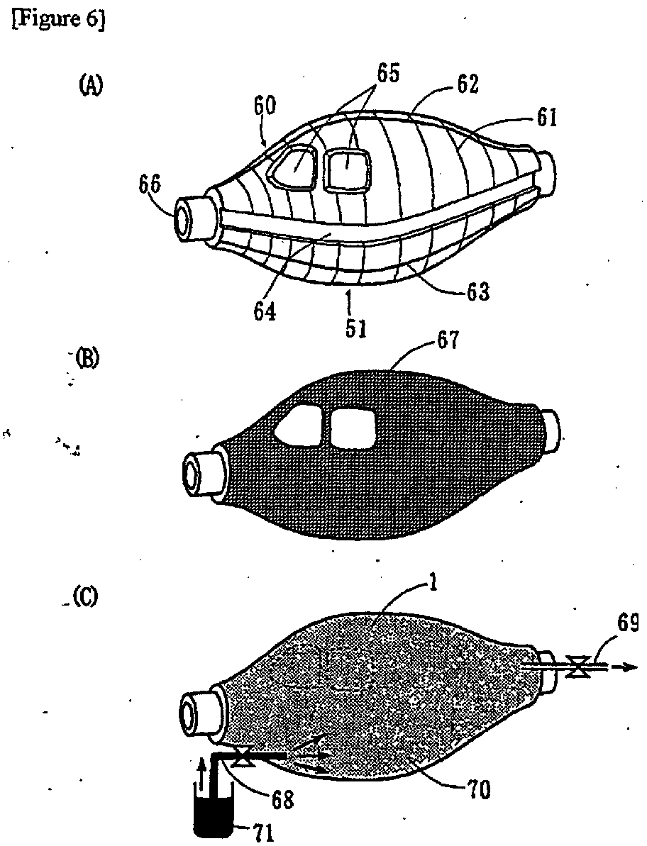
Description
The present invention relates to a fibre-reinforced plastic
(FRP) structure having a solid of non-revolution shape hollow
section (hereinafter a 'fibre-reinforced plastic structure
with a hollow section' is referred to as an 'FPR structure
with a hollow section' or as a 'hollow FRP structure') such
as, for example, an aircraft fuselage, an automobile body or
a fluid transportation means, and to an improvement in the
method of production thereof. In particular, it relates to
an FRP structure with a hollow section having the shape
feature of comparatively small openings compared to the size
of the internal cavity and, moreover, which is light in
weight and high in strength, so is ideal for use for modes of
transport such as the aircraft and automobiles as
aforementioned; and to a method of production which enables
this structure to be produced simply and with good production
efficiency.
Recently FRP structures have been a focus of attention as
structures in cases where a light weight and high strength
are demanded, such as for example modes of transport like
automobiles and aircraft, containers for the storage or
conveyance of gases and liquids, sports goods such as golf
club shafts and fishing rods, and building structures such as
earthquake-resisting reinforcements.
Of these FRP structures, in the case of pressure vessels for
example, hollow FRP structures with comparatively small
openings are ideally employed. Such hollow FRP structures
are normally produced by the so-called filament winding
method in which resin-impregnated reinforcing fibre tow is
wound onto a rotating liner and then curing carried out.
However, hollow FRP structures produced by the filament
winding method are limited to solid of revolution shapes
where the internal/external shape in the cross-section
perpendicular to the axis of rotation is substantially
circular in each case. That is to say, only solid of
revolution shapes are known as FRP structures with a hollow
section where the openings are small compared to the interior
width (diameter). Moreover, in cases where the ratio of the
interior maximum width to the maximum width of the openings
is at least 1.1, it is not possible to withdraw the inner
mould from the opening, so it is withdrawn for example by
cutting the inner mould using a cutter as disclosed in US
Patent 3,220,910. In such circumstances, there are limits to
such a cutting system when forming a structure of the kind
containing ribs.
Now, in the case of modes of transport, gasoline tank
containers and the like, in order to reduce transportation
costs it is naturally preferred that these be lightweight
hollow structures and also light in weight but, if they are
restricted to a solid of revolution shape, problems arise
such as the internal space not being as efficiently employed
as intended and the aerodynamic resistance, which depends on
shape, not being optimized. Moreover, there are also
problems in terms of design, and so the use of conventional
solid of revolution shape hollow FRP structures, as they are,
has been difficult.
If an FRP structural material which is not of hollow section
and a number of hollow FRP structural materials with relative
large openings are coupled together to form an integral unit,
then it is possible to produce fairly complex shape hollow
structures but, in such circumstances, the strength and
rigidity at the regions of the joints is reduced and a weight
increase is brought about by the jigs and the like employed
in the coupling, so the particular characteristics of an FRP
in being lightweight and high in strength and rigidity are
readily lost. Moreover, there is the problem that the work
required for the coupling brings about an increase in cost.
On the other hand, in the case of FRP structures with a
hollow section used for large size modes of transport, where
a number of openings of various shapes is demanded and which
are comparatively complex overall, there are examples of
structures which are composed of a plurality of FRP moulded
elements with these being coupled together to form the
structure as a whole. However, if all said plurality of FRP
moulded elements have an open shape, the structure formed by
coupling them together does not possess regions which are
continuous in the circumferential direction, so there is the
problem that the strength and overall rigidity as a structure
tends to be relatively low.
Again, with regard to the aforesaid hollow FRP moulded
elements with a closed space, that is to say having a
continuous closed curved surface region in the
circumferential direction, in the case where the sectional
shape in which the closed curved surface region has been
continuously formed is comparatively small, for example in
the case of a pipe, moulding techniques have been established
by pulltrusion or by the so-called filament winding method in
which resin-impregnated reinforcing fibre tow is wound onto a
mandrel and then curing performed, but it cannot be said that
a moulding technique has yet been established for hollow FRP
structures which are of comparatively large size with an
overall length of several metres, and which also have
openings at the ends or along the length, and where the
closed curved surface region is not continuous over the
entire length.
In other words, with conventional hollow FRP structures,
because of limitations on their shape and dimensions, it has
frequently been difficult to employ them favourably for
example as modes of transport or as containers of various
shapes.
Furthermore, in the case of production methods too, for the
purposes of producing comparatively large moulded bodies,
methods employing an elastic inner mould where moulding is
carried out under internal pressure to expand said inner
mould are disclosed in US Patent 5,059,377, JP-A-54-13571 and
JP-A-11-48318, but these are totally different from the
method where a dry reinforcing fibre substrate is bagged, and
resin injected in the low pressure state, which is method of
the present invention, and they are methods in which lay-up
is performed using a substrate material to which resin has
already been applied, after which blow moulding is performed,
or where blow moulding is performed while heating a substrate
comprising a woven mixture of thermoplastic fibre and
reinforcing fibre. Consequently, there are problems such as
poor working characteristics because of the resin tackiness
and it not being possible to deal with detailed and complex
shapes. In terms of structure too, no interior width is
broader than the maximum width of the openings, so relatively
simple structures are the objective.
In other words, there does not exist at present any method
for dealing with the structures which are the aim of the
present invention, which are comparatively large hollow FRP
structures having an interior maximum width greater than the
maximum width of the openings and where this interior maximum
width is at least 0.5 m, and where the shape of the structure
is of a solid of non-revolution shape such as a complex shape
having a protruding rib structure arranged at the inner face.
The present invention has as its objectives to resolve the
problems of conventional hollow FRP structures as described
above, and to provide a solid of non-revolution shape hollow
FRP structure having an integral construction, where the FRP
characteristics of light weight, high strength and high
rigidity can be manifested to a maximum, enabling it to be
favourably used for modes of transport and for containers of
various kinds; and to a method for the production thereof.
One embodiment of the fibre-reinforced plastic structure with
a hollow section according to the present invention, which
enables the aforesaid objectives to be realized, is a fibre-reinforced
plastic structure with a hollow section which is
characterized in that
Another embodiment of the fibre-reinforced plastic structure
with a hollow section according to the present invention is a
fibre-reinforced plastic structure with a hollow section
which is characterized in that
Figure 1 is a perspective view showing an example of a hollow
FRP structure where the present invention can be applied.
Figure 2 is a perspective view showing another example of a
hollow FRP structure where the present invention can be
applied.
Figure 3 is a perspective view showing still another example
of a hollow FRP structure where the present invention can be
applied.
Figure 4 is a perspective view showing still another example
of a hollow FRP structure where the present invention can be
applied.
Figure 5 is a perspective view showing still another example
of a hollow FRP structure where the present invention can be
applied.
Figure 6 is a schematic structural view showing an example of
an FRP moulded body moulding method relating to the present
invention.
Figure 7 is a schematic structural view showing another
example of an FRP moulded body moulding method relating to
the present invention.
Figure 8 is a sectional perspective view showing an example
of a liner moulding method based on an inner mould with a
concave groove, according to the present invention.
Figure 9 is a schematic structural view showing an example of
an FRP moulded body structure relating to the present
invention which is different from Figure 1.
Figure 10 is a perspective view of a hollow FRP structure
relating to still another example of the present invention.
Figure 11 is a perspective view of a hollow FRP structure
relating to still another example of the present invention.
Figure 12 is a perspective view of a hollow FRP structure
relating to still another example of the present invention.
Figure 13 is a schematic structural view showing an example
of the method of moulding the still another FRP moulded body
relating to the present invention shown in Figure 9.
Figure 14 is a schematic structural view showing another
example of a method of moulding an FRP moulded body relating
to the present invention.
Figure 15 is a schematic structural view showing another
example of a method of moulding an FRP moulded body relating
to an example of the present invention.
Figure 16 is a schematic structural view showing still
another example of the rib of an FRP moulded body relating to
the present invention.
Figure 17 is a schematic structural view showing still
another example of the rib of an FRP moulded body relating to
the present invention.
Figure 18 is a schematic structural view showing still
another example of the rib of an FRP moulded body relating to
the present invention.
Below, preferred modes of practice are described and a
detailed explanation is provided in relation to the hollow
FRP structure with a hollow section of the present invention,
its method of production and the inner mould used for the
moulding.
Reference in the present invention to a hollow section
indicates that in a given section of the hollow FRP structure
the space formed in the structure interior is enveloped by an
outer peripheral portion comprising moulded body and it does
not have an opening or passageway through to the outside.
Furthermore, a closed space indicates a region over which
such a hollow section continues in the lengthwise axial
direction. That is to say, it is a region which does not
connect with the outside in the circumferential direction.
Now, with regard to this closed space, while it is not
impossible for it to be a space which does not connect with
the outside at all, like the interior of a ball, this is not
very practical and, as a rule, it will connect to the outside
via regions having openings at the ends of structure in the
longitudinal direction or having openings part way along the
length thereof, that is to say via regions which do not
themselves form closed spaces. Now, there are no particular
restrictions on the longitudinal direction length of such a
closed space and this can vary according to the application
and the objectives, so cannot be precisely stipulated but,
broadly speaking, it is preferably at least 0.2 m and/or at
least 10% of the overall length. Below this numerical range,
it may lack practicality due to falling below the lower limit
of rigidity for moulding a hollow structure.
Now, a solid of non-revolution shape denotes any three-dimensional
shape which is not a solid of revolution shape.
A solid of revolution shape essentially denotes a three
dimensional shape obtained from the locus when a plane figure
shape is rotated, and it includes the sphere, ellipsoid of
revolution, cone, cylinder and multi-tapered cylinder, etc.
As the solid of non-revolution shapes in the present
invention, shapes which have an axis of symmetry are
particularly preferred. Now, in the present invention the
structure is not to be restricted to one where each and every
section is non-spherical. A shape can still be a solid of
non-revolution in its three dimensional form even though each
section is spherical (for example, the case of a solid of
spherical section where the equation for the longitudinal
axis is Y = X2 (-0.5 < X < 0.5), that is to say z2 + (y - x2)2
= (r2 - 2*x2)2 [-r < x < r, f = constant], etc). Naturally,
these are included amongst the shapes of the structure of the
present invention.
The solid of non-revolution shape FRP structure relating to
the present invention comprises a hollow shape, and reference
to a hollow shape denotes a shape which essentially possesses
an inner space such as a shell shape, tsuzumi drum shape,
pipe shape or the like, and the inner space and the space
outside are connected by an opening at one or more than one
location. Such openings can be utilized for the entry and
exit of people or hands, the introduction or removal of
luggage, or as inlets/outlets for accommodating grain,
liquids, gases or the like inside.
One of the characteristics of the FRP structure with a hollow
section of the present invention is that it has a hollow
shape with an interior maximum width greater than the maximum
width of the openings.
The maximum width of an opening in the present invention is
the maximum value of the distances across the opening and, in
terms of dimension, it denotes a large size of at least 1 m.
For example, in the case where the opening is round, the
maximum width of the opening corresponds to its diameter,
while in the case where the opening is elliptical it
corresponds to the major axis, and in the case where the
opening is rectangular it corresponds to the diagonal. In
the case where the opening forms a curved surface, the
maximum width is taken as the maximum value of the straight
lines drawn between any two points around the edge of the
opening.
The interior maximum width of the cavity in the main body
region in the present invention is the maximum distance
across the inner space. In such circumstances, the direction
in which the length is measured is in a plane parallel to the
plane of the opening, and the maximum length within this
parallel plane is taken as the interior maximum width.
Now, in the case where there are openings at two or more
places, for such hollow FRP structures of the present
invention the same applies to all said openings and the
interior maximum width will be greater than the maximum width
of the openings. Furthermore, the openings may also be other
than at the two ends.
The ratio of the interior maximum width to the maximum width
of the opening(s) needs to lie within the range 1.1 to 500,
and it is preferred that it lie within the range 1.2 to 100.
A ratio within the range 1.5 to 50 is still further preferred.
If it is smaller than the lower limiting value of this range,
the internal space will be insufficient, while if it greater
than the upper limiting value then, in the case of a vehicle
or container for example, cleaning or washing of the inside
will be troublesome. Again, it is preferred that sections
having a sectional maximum width (the maximum width within a
given section) of at least 1.2 times (more preferably at
least 1.5 times) the maximum width of the opening extend in
the longitudinal direction at least 0.1 m (more preferably at
least 0.5 m) and/or that they be at least 5% (more preferably
at least 20%) of the total length. In such circumstances,
the magnitude of the sectional maximum width of sections
satisfying this condition may be the same or they may be
different, for example they may continuously vary. Below the
lower limiting value of this range, the interior space will
be inadequate and the space for accommodating people may be
narrow and uncomfortable. This is a particularly important
condition in applications relating to modes of transport such
as aircraft and cars.
Based on this characteristic of shape, it is possible to
obtain an interior space which is comparatively large in
terms of the size of the openings. On the other hand, there
are shapes where it is essentially impossible to withdraw a
body filling the internal space without division or
distortion.
The solid of non-revolution shapes in the present invention
include those with left/right symmetry and those with
top/bottom symmetry. Due to the fact that it is a solid of
non-revolution shape, the hollow FRP structure of the present
invention can be applied to a variety of applications such as
modes of transport and containers of various kinds. Modes of
transport include airliners, planes, helicopters and other
such flying machines, cars, buses, trucks, motorcycles,
bicycles, and passenger ships, sailboats, motor boats,
leisure craft and other such vessels, trains, high speed
trains and other such rolling stock, and also distribution
equipment and the like. As described below, the hollow FRP
structure of the present invention is outstanding in its
mechanical characteristics, so is suitable for large size
structures of several metres and above.
Now, hollow FRP structure in this invention includes
structures where the main constitutional portion is
substantially integrally moulded without having joined
regions, and also structures composed of a plurality of
moulded elements at least one of which is composed of a
region forming a closed space and substantially integrally
formed.
The former does not contain parts joined together by means of
rivets, bolts and the like, and is substantially integrally
formed. Consequently, since there is no cutting of the fibre
as in the case where there are parts which are joined
together, the strength is high, the wall thickness can be
reduced, productivity is high and it is possible to reduce
the weight and lower costs. In particular, with a large
structure of more than a few metres, the load due to its own
weight is high and a limit arises in terms of the size of the
structure where parts are joined together but, by integral
formation and employing thin walls, larger structures are
possible. However, there is no objection to the addition of
fitments or the like by means of fastening or bonding.
Furthermore, as a result of integral formation, since there
are regions free of joined parts over the entire
circumferential direction length, extremely high strength and
rigidity are manifested and a highly reliable structure is
formed. Moreover, it can be said to be an extremely low cost
structure in that there is no need for the "criteria"
(quality control and inspection) employed to ensure the
strength of joined parts. Now, the joined parts referred to
here are the joints used for structure formation and they do
not include the fitment merely of accessories (such as hinges
for door attachement, etc) by bolting and the like.
Furthermore, it is preferred that the jigs (pins, screws,
sheets and blocks, etc) used for accessory coupling which
comprise metal or plastic be integrally formed beforehand by
insert moulding.
A section in this main body portion circumferential direction
forms a hollow section which constitutes a closed space.
Moreover, closed space regions, where an integral structure
is formed substantially without parts which are joined
together, are preferably positioned at the ends of the
aforesaid main body portion and/or in the centre thereof.
The second type of aforesaid structure is the case where a
specified hollow FRP structure is constructed by coupling a
number of moulded elements by adhesion or by local vacuum
moulding, so the moulding of the individual moulded elements
is easy and the total structure can be produced cheaply.
Here again, the FRP moulded body which constitutes the chief
structural part thereof has a region of hollow section having
an integrally moulded structure extending around the entire
circumferential direction length and forming a closed space,
so at least in this part there is formed a substantially
integral structure in which no joined parts are present. The
greater proportion (preferably 80 vol% and more preferably
90 vol%) of the reinforcing fibre arranged in the
circumferential direction within this FRP moulded element is
not cut over a length of one lap or more, to give high
strength and high stiffness, and to maintain a high strength
and rigidity in the FRP moulded body as a whole.
Consequently, even in the case of a hollow FRP structure
constructed using a plurality of moulded elements, overall a
high strength and high modulus are maintained.
Now, it is possible to produce a structure in which the
portion forming a closed space and having a substantially
integral structure is produced at the end of the aforesaid
FRP moulded body and/or in the centre of said FRP moulded
body.
Furthermore, by producing a joined structure comprising a
plurality of moulded elements, to form the aforesaid hollow
FRP structure as a whole, there may be realized ease of
moulding and finishing of the respective moulded elements,
and there may be realized ease of coupling of the moulded
elements and ease of interior finishing when assembling the
hollow FRP structure and producing the final product, so as
well as production being simplified it is also possible to
lower overall cost. Again, by forming suitable openings in
the aforesaid FRP moulded elements, the coupling to other
moulded elements can be simplified and, furthermore,
finishing of the hollow FRP structure interior and internal
decorative operations are made extremely easy. Consequently,
openings are preferably placed at the ends.
In the case of both types of structure, in the portion where
there are no joined parts over the entire circumferential
direction length, there may be included either regions in
which the FRP extends linearly in the circumferential
direction or regions where it extends curvilinearly. Of
course, on the inner or outer face of the hollow structure,
there may be flat bodies, curved bodies or ribs or other such
projections.
Moreover, being a substantially integral structure, there is
no need for reinforcement by increasing the amount of
material used (increasing the wall thickness) as in a joined
structure, and the problem does not arise of the structure
being overly divided and there being many regions requiring
reinforcement, leading to a loss of the light weight which is
characteristic of a composite material.
In order that such effects are reliably manifested, it is
preferred that at least 20%, and more preferably at least 30%,
of the total length of a structure used for a mode of
transport or of a structure used for a container comprises a
hollow FRP structure moulded as an integral structure. Of
course, ideally the entire length of the structure used for a
mode of transport or of the structure used for a container
will be composed of said hollow FRP structure.
In order to secure still higher strength and rigidity, it is
preferred that the inner face of the aforesaid structure has
a projecting rib (or ribs) projecting in the radial direction
thereof. Furthermore, said projecting rib preferably has a
frame structure where a core material is present in the
interior and this is surrounded by a skin layer containing
reinforcing fibre. Now, with regard to the FRP structure of
the present invention or section thereof, the term "radial
direction" is not to be restricted to the radius of a circle.
In the present invention, broadly speaking, a radial
direction denotes a direction radiating towards the outside,
taking the centre of gravity of the hollow section as the
centre.
In the aforesaid structures, the main body portion is
preferably formed with a shell comprising an aforesaid skin
layer positioned on the outside and a core material
positioned on the inside.
The inside of the aforesaid core material is formed
preferably with a shell comprising fibre reinforced plastic
skin layers. It is further preferred that the core material
has a rib extending in the radial direction of the structure,
and that it comprises a foam and that grooves be formed in
the surface thereof.
The reinforcing fibre used in the fibre-reinforced plastic
from which the main body portion is composed can be a known
reinforcing fibre such as an inorganic fibre like carbon
fibre, glass fibre, SiC type fibre, alumina fibre, boron
fibre or metal fibre, or an organic fibre like an aramid
fibre, high density polyethylene fibre, PBO (polybenzoxazole
fibre), polyarylate fibre or the like, but from the point of
view of light weight together with high strength and rigidity,
the use of carbon fibre is preferred. In particular, carbon
fibre having an elastic modulus in tension of 200 GPa or more,
or carbon fibre of tensile strength 4 GPa or more is
preferred. In the case of a mode of transport where there is
the possibility of impact, the use of carbon fibre of
elongation at least 1.5%, and more preferably at least 2.0%,
which is outstanding in its impact resistance, is preferred.
The carbon fibre elastic modulus and strength can be measured
based on JIS-R7601, and the elongation can be determined by
dividing the strength by the elastic modulus.
Now, in the case where the structure is subject to torsion,
the torsional modulus of elasticity of the reinforcing fibre
is preferably within the range 5 to 30 GPa. The torsional
modulus of elasticity of a fibre can be measured by the
method described in JP-A-1-124629.
Furthermore, in order to reduce the amount of thermal
expansion/contraction of the hollow FRP structure and to
suppress the occurrence of gaps at the openings, it is
preferred that the coefficient of thermal expansion of the
reinforcing fibre lies in the range -0.1 x 10⁻⁶ to 30 x 10-6/°C.
Again, where fuzz on the strands determined by the method of
measurement described in JP-B-1-272867 is no more than 30 per
metre, a structure of high reliability is obtained, so this
is preferred. This is because, if there is more fuzz than
this, there is a possibility of yarn breaks occurring during
the moulding described below.
Glass fibre is preferred from the point of view of insulation,
impact resistance and cost. Organic fibres are also
preferred in cases where insulation is to be provided.
Where the hollow FRP structure serves as a mode of transport,
it will be subject to frequent outdoor exposure, so there are
the effects of rain and UV, and the possibility of being
struck by lightning. Thus, in such circumstances, it is
preferred that there be used a so-called 'hybrid fibre' where
there is jointly employed aforesaid carbon fibre which is
outstanding in its environmental resistance and glass fibre
or organic fibre which is outstanding in terms of insulation.
Hybrid types range from those where the different fibre types
are interlaced at the yarn/filament level to those where they
are distributed in layers or sheets. Furthermore, there are
of course included those cases where they are distributed in
strand form, as in a covered yarn.
In the case where the hollow FRP structure is a container,
tank or a storage vehicle, there will be stored in the
interior thereof grain or other such solids, gasoline or
other such liquid, or gases of various kinds, so carbon fibre
of low moisture sorption and/or glass fibre of high
resistance to gas corrosion is preferred.
With regard to the form of the reinforcing fibre, there can
be used a unidirectional preform, a woven material, a mat or
the like, or combinations of these, but a continuous fibre
form is preferred in the terms of the properties of the
structure. In particular, it is most preferred that there be
present reinforcing fibre which continues along the entire
lengthwise direction of the structure. Woven material
employing aforesaid fibre of elongation at least 2% is
preferred because of its outstanding impact resistance. In
the case of glass fibre woven fabric, there is little
anisotropy and stress concentrations can be mitigated, so
this is suitable for regions of stress concentration such as
openings, holes, slits and the like.
Furthermore, in order to raise productivity, it is preferred
that there be used a so-called thick reinforcing fibre tow
comprising a bundle of 12,000 to 200,000 filaments.
The volume content of the reinforcing fibre is preferably in
the range 35-70%. If the volume content is below this range,
there is a tendency for properties of the structure such as
strength to be lowered, while, conversely, if the content is
too high, difficulties may arise with the resin impregnation,
and there are problems such as increased cost. The
proportion of aforesaid carbon fibre in the reinforcing fibre
is preferably from 5 to 100%, by volume content. Now, the
volume content can be measured by the method specified in
JIS-K7052 or JIS-K7075.
As the matrix resin from which the FRP is composed, there can
be used an epoxy resin, unsaturated polyester resin, vinyl
ester resin, phenolic resin, modified epoxy resin or other
such thermosetting resin, a polyamide resin, polyethylene
terephthalate resin, ABS resin, polyetherketone resin,
polyphenylene sulphide resin, poly(4-methylpentene-1) resin,
polypropylene resin or other such thermoplastic resin, or a
rubber material or the like. Of these, from the point of
view of enhancing the mechanical characteristics, epoxy
resins, unsaturated polyester resins and vinyl ester resins
with good adhesion to the reinforcing fibre are preferred.
Again, from the point of view of improving the impact
resistance, nylon or other thermoplastic resin, or a modified
epoxy resin where an epoxy resin is modified with a
thermoplastic resin or rubber, is preferred. Again, in
applications where nonflammability or flame retardance is
demanded, such as for vehicles, a phenolic resin or a mixture
of inorganic flame retardant with an unsaturated polyester
resin or vinyl ester resin, is preferred.
The hollow FRP structure of the present invention can be
produced on a high-performance low-cost basis by, for example,
the resin transfer moulding (RTM) method in which a substrate
comprising the aforesaid reinforcing fibre is laid-on or
wound-around the outside of an inner mould after which resin
is injected into the substrate and curing carried out. There
may optionally be introduced into the substrate, between the
reinforcing fibre and/or at one face thereof, a lightweight
blown material comprising a polymer material, a ceramic
material or a metal material, or a honeycomb material, powder,
granular material, sheet-shaped material or the like.
The inner mould can be composed of various materials such as
wood, plastic, foam, low-melting alloy, water-soluble polymer,
wax, glass, gypsum, rubber, ceramic, paper, clay or ice. It
will have a shape close to that of the target hollow FRP
structure and it has the role of maintaining the three-dimensional
configuration of the substrate until the cured or
semi-cured state is attained. Hence, it may be removed after
the curing or semi-curing of the resin. However, the inner
mould may also be left as an integral part of the hollow FRP
structure after moulding.
Moulding is possible using either a hollow or solid inner
mould but a hollow inner mould is preferred, not merely
because it is lightweight but also because, by applying a
surrounding vacuum or applying an internal pressure and
causing the inner mould to expand, it is possible to bring
about straight aligning of the reinforcing fibre and an
enhancement in strength by raising the FRP fibre content.
When the inner mould is light in weight, then it has
outstanding handling characteristics such as being moveable
at the time of moulding, so it is labour-saving and safe.
Again, even in the case where the inner mould is left in the
FRP moulded body, it is still possible to ensure a large
interior space. Furthermore, less material is used for the
inner mould so this is advantageous too economically.
The substrate and the resin from which the hollow FRP
structure is composed comprise the aforedescribed reinforcing
fibre and resin, and at the time of the resin injection there
can be adopted the so-called vacuum bag method in which the
inner mould and the reinforcing fibre substrate are covered
over with a bag film, then the pressure in the bag interior
reduced and the resin injected. Again, as stated above,
there can also be adopted a vacuum moulding method in which,
with a covering material interposed between the inner mould
and the reinforcing fibre substrate, pressure-reduction is
effected between the inner mould and an outer mould described
below, after which the resin is injected. In such
circumstances, said covering material is preferably an
elastic material. This is because, by possessing elasticity,
even in cases of a complex shape such as when the interior
structure of the moulded body has projections, moulding is
possible without marked distortion of these projecting
regions between the inner mould and the substrate. The
covering material may be an elastic material comprising
rubber or other polymer material separately produced from the
inner mould or it may also be an elastic material formed as a
coating or the like on the outer face of a splittable or
integrally-formed inner mould. Furthermore, the elastic
material need not merely secure a vacuum between it and the
outer mould, but can also suppress resin accumulation in gaps
between the substrate and inner mould caused by the slight
discrepancies in inner mould distortion which readily arise
at the corners of the projecting regions, such as ribs,
formed on the inner mould, or it can facilitate mould release
or can act to reduce distortion or movement of inserts such
as fitments. In order that the shape of the moulded body not
be harmed, the preferred thickness of the covering material
is about 0.1 to 2 mm. Again, the elongation of the elastic
material is preferably at least 3%.
Furthermore, the aforesaid covering material may also be used
as a medium having the function of lowering the flow
resistance of the resin and enhancing its diffusion
efficiency (that is to say, as a resin diffusion medium), and
for example if there is arranged a plastic net, mesh, mat or
the like, the resin diffusion rate is increased, there is
smoother flow into fine regions, and the moulding
characteristics are markedly improved.
Again, it is preferred that grooves of depth in the range
from a few millimetres to a few centimetres be formed in the
inner mould surface. Specifically, it is preferred that the
depth thereof lies in the range from 1 to 50 mm (more
preferably 3 mm to 1 cm) and that the spacing of the grooves
is about 5 to 900 mm (more preferably 10 to 100 mm).
Moreover, the grooves may mutually cross or they may be
formed in parallel. Such grooves form channels in which the
resin flows at the time of the resin injection. They also
form passageways for the air inside the bag to travel along
when a vacuum is applied, so that air from within the
substrate is readily eliminated and the resin passes
everywhere throughout the substrate (to envelop the
individual reinforcing fibres). Thus, mouldings are obtained
which have few voids, possess outstanding mechanical
properties and are of high reliability.
Now, the amount of voids in the hollow FRP structure is
preferably no more than 2% by volume and more preferably no
more than 1.5%. The void content can be determined from the
specific gravity but, as an alternative method, any section
of the moulded body is abraded using sandpaper (fine material
of grade #1000 or better) and buffing (particle size of the
polishing powder no more than 5 µm) until the fibre is
exposed, and then the area of voids determined using an
optical microscope at a magnification of 500. In such
circumstances, a more accurate measurement of the void
content can be made by taking an observation area of at least
50 mm2.
In the case of a hollow FRP moulded body produced in this way,
where ribs are formed on the inner face of the FRP
corresponding to grooves in the inner mould, the rigidity is
raised and a more stable structure is formed. In particular,
in flat planar regions of large area, buckling is made more
difficult by ribs and so this is particularly preferred for
structures employed for modes of transport and the like.
In terms of enhancing the rigidity of the hollow FRP
structure, it is preferred that there be provided, for
example, an aforesaid rib-shaped liner in the interior of the
hollow FRP structure. In particular, in structures for modes
of transport having three or more openings, a liner is
extremely effective for enhancing the rigidity. As the liner,
there can be used a reinforcing fibre-containing polymer or
ceramic sprayed material, a gel coat, a phenolic or other
face panel, a titanium alloy, aluminium alloy, magnesium
alloy or other light metal sheet or rod material, various
types of foam material, and combinations of two or more of
these materials. The liner does not need to be present over
the entire inner face of the hollow FRP structure, and it may
be provided locally, for example around openings or in
regions which include the centre of a broad curved face or
flat face portion. The liner may be, for example, a FRP or
metal stiffener, spar, stringer or the like which is
separately moulded from the hollow FRP structure, or it may
be a stiffener, spar, stringer or the like integrally-moulded
along with the hollow FRP structure. Now, stiffener, spar
and stringer refer to, for example, a girder, rib, framework,
frame or reinforcing material.
The cross-sectional shape of the liner may be round, C-shaped,
hollow square-shaped, hat shaped, T-shaped, I-shaped, Z-shaped,
S-shaped or the like. The C-shape and hat-shape
sections, which are hollow, are preferred in terms of
enhancing rigidity, and furthermore the introduction of a
lightweight material such as a foam into the hollow region is
further preferred (see Figure 8). In Figure 8, there is a
concave groove 64 provided on the outer face of the inner
mould which is used for moulding the liner and there are
preferably a plurality of such concave grooves for rigidity
enhancement by the liner. Again, if the liner has a cavity,
this is preferred in terms of weight reduction, and it can
also be advantageously employed in some applications, such as
for the circulation of a fluid for heating/cooling, as flow
channels for fuel, lubricating oil or the like, or as
passages for wiring or the like. Now, in an FRP liner, it is
preferred that there be employed unidirectionally-aligned
reinforcing fibre, for raising the rigidity.
Again, providing a groove in the aforementioned lightweight
material so as to carry out the resin impregnation more
effectively, also constitutes a preferred embodiment.
Specific examples of the lightweight material are urethane
foam, polystyrene foam, polyethylene foam, polypropylene foam,
phenolic foam, urea foam, polyvinyl chloride foam, silicone
foam, epoxy foam, polyimide foam, polyester foam, melamine
foam and other such lightweight foams, and wood such as balsa
wood or the like, where these have an apparent specific
gravity in the range about 0.02 to 0.9. Of these, polyimide
foam is preferred in structures for modes of transport, where
fire retardance is strictly demanded. The torsional rigidity
of wood such as balsa wood is high and it does not readily
buckle under shear, so it is also preferred. The aforesaid
groove in the lightweight material provided for resin flow
may also serve as the groove 81 shown in Figure 8 in the
resin-filled state, or it may be different therefrom.
By suitable selection of the type of liner, it is possible to
improve properties of the structure such thermal insulation,
vibration damping, sound proofing, impact resistance and the
like.
At the time of the production of the aforesaid hollow FRP
structure, the application of pressure to the outside of the
substrate material by placing in an outer mould which divides
into two or more parts, is also preferred. The outer mould
may be in direct contact, or in indirect contact via a buffer
layer such as a bag film, rubber or air cushion. The most
preferred pressure lies in the range from 0.5 kg/cm2 to
20 kg/cm2. By the action of an exterior pressure, the
solubility of gas incorporated into the resin is raised, with
the result that voids in the FRP moulded body are reduced and
the mechanical properties of the structure are enhanced. If
the outer mould is a material such as metal with high
rigidity, the clasping force can be increased. Again, by
accurate finishing of the inner face of the outer mould, it
is possible to give the surface of the hollow FRP structure a
smoother finish. By providing a smooth finish, the
mechanical processing of the surface which has been necessary
hitherto becomes unnecessary and so costs can be reduced. A
smooth surface in the case of a mode of transport not only
lowers air resistance and improves fuel efficiency, but it
also reduces noise such as that produced by rushing wind and
the like. Again, in cases of falling rain and the like,
there is the advantage that the water droplets can run off.
In addition, being smooth, painting is easier.
When performing moulding using an outer mould, there should
be provided a vacuum port for pressure reduction and a port
for resin injection in the outer mould or inner mould. If
provided in the outer mould, the usability is excellent,
while if provided in the inner mould there is the feature
that no marks are left in the outer face of the moulded
material. Thus, appropriate selection may be made. Again,
there is also the possibility of providing these ports other
than in the outer mould or inner mould by design of the mould
or jig structure.
With regard to the material for the outer mould, in the case
where heat resistance or high accuracy is required, a metal
material or ceramic material is preferred, whereas in the
case where lightness of weight or economy are necessary, an
FRP or wood material is preferred.
The outer mould is dividable into two or more parts, with
more parts being used the more complex the shape, such as
when the inner mould has projecting regions, and this
facilitates removal from the outer mould. Taking into
account a balance in terms of cost, it is most preferred that
it can be divided into about 3 to 6 parts.
Methods for heating the outer mould include direct heating
methods such as inserting a heating element into the outer
mould or using a flow of heating medium, and indirect heating
methods such as with an infrared heater or other such heater,
or piping through which a heating fluid circulates, provided
in the vicinity of the exterior surface of the outer mould.
In the case where the outer mould is made of metal, it is
possible to perform heating by passing electrical current
through the outer mould. Direct heating is preferred in that
the resin curing time can be reduced and the moulding cycle
shortened. Again, it is also effective in that it is
possible to increase the maximum attainable temperature.
Indirect heating is useful in cases where it is necessary to
simplify or lighten the outer mould. Indirect heating is
suitable when the thickness of the outer mould lies in the
range about 2 to 300 mm.
Furthermore, it is also possible to produce a structure where
a covering layer is integrally formed at the outer face of
the FRP. For example, in order to obtain a smoother surface,
it is preferred that a gel coat be applied to the inside of
the outer mould, so there is integral moulding of the gel
coat with the FRP. Any known gel coat can be used such as an
epoxy gel coat, polystyrene gel coat or urethane gel coat,
but it is further preferred that there be used a resin of the
same type as the FRP or a material of similar coefficient of
linear expansion. This is because thermal stress produced by
temperature differences may cause separation to occur. The
gel coat is not a structural member so it is preferred that
its thickness lies in the range from 0.1 to a few mm. Within
this range, the lightness is not impaired and the surface
smoothness is maintained.
In order to enhance the operational characteristics when
arranging the substrate material on the outer face of the
inner mould and to achieve close adhesion to the outer mould,
it is effective to apply an outwardly-directed force in the
inner mould, for example to apply an internal pressure. The
preferred pressure lies within the range 0.5 to 10 kg/cm2,
with the range 1.0 to 5 kg/cm2G further preferred, In such
circumstances, the internal pressure may be applied by means
of a gas such as compressed air, or, where required, there
may be used water or other such non-compressible pressurizing
medium. Appropriate control of the internal pressure during
the production process is also effective. For example,
control is possible such that, when arranging the substrate,
priority is given to workability and so the pressure is
lowered, and then thereafter the pressure is raised so that
the inner mould expands, causing the slack in the reinforcing
fibre of the substrate to be eliminated.
Furthermore, depending on the particular inner mould material,
it is also possible to carry out the same kind of control by
means of heat. That is to say, the same effects as applying
pressure can be obtained by heating the inner mould and
causing it to expand.
Moreover, in the case where the inner mould is a magnetic
substance or contains a magnet, it is possible to cause the
inner mould to expand by applying a magnetic field. Since
there is no contact, and since adjustment of the amount of
deformation of the inner mould is readily possible by control
of the magnitude of the magnetic field, the accuracy of the
moulded body can be increased. Typical examples of magnetic
substances are ferrite, permalloy, nickel alloy, iron and
other such metal materials, of which super-permalloy,
supermalloy and other such ferromagnetic materials containing
molybdenum, manganese and chromium, and ferromagnetic
materials such as manganese-zinc ferrite, nickel-zinc ferrite
and magnesium-manganese ferrite are preferred, in that a
large force can be generated when the inner mould is made to
deform.
Again, by inserting reinforcements which can be assembled or
enlarged such as umbrella reinforcements, rigidity can be
enhanced and it is also possible to facilitate the securing
of the semicured substrate and the carrying out of the
reinforcing fibre winding operations.
In the case where the inner mould comprises an airtight
material such as a plastic or an FRP, the internal pressure
may be directly applied to the inner mould but in the case of
a dividable inner mould assembled from block-shaped and/or
sheet-shaped materials comprising wood or metal for example,
a balloon may be inserted into the interior of the inner
mould and this then made to expand.
Now, in the case where an outer mould is used in direct
contact with the substrate, for the purposes of enhancing the
release properties between the outer mould and the FRP which
forms the moulded body, it is preferred that a release
material be inserted between the FRP and outer mould. As
examples of the release material, there are "Teflon" film and
"Teflon" rubber or silicone rubber. In the case where film
is used, the outer shape of the inner mould will be roughly
the same as the hollow FRP structure, but in the case of a
semi-solid such as silicone rubber the inner mould does not
necessarily need to resemble the target structure. It can
have a cheaper and more simple form, and the shape of the
target moulded body can then be imparted to the semi-solid.
Since the level of distortion of a semi-solid material is
high, even when it has a rather complex shape with, for
example, projections or the like, it can be removed without
damaging the structure. Moreover, a semi-solid material can
also be reused after carrying out the release treatment.
If, when arranging the substrate on the outer face of the
inner mould the reinforcing fibre of the substrate extends
for two or more laps of the circumference of the hollow inner
mould, the pressure from the hollow inner mould is
concentrated only in the reinforcing fibre and it is
difficult to uniformly apply pressure to the structure as a
whole. Moreover, by applying pressure to the interior, the
hollow inner mould is made to expand radially and,
furthermore, the reinforcing fibre also made to move a little
to produce a slack-free state, so if the fibre extends for
two or more laps then this movement will be impeded. As a
result, the FRP structure may not be moulded to the desired
shape and dimensions, and the escape of bubbles or the
diffusion of resin may be inadequate, so that the
characteristics of the FRP structure are not fully manifested.
Consequently, it is preferred that arrangement of the
substrate be carried out such that reinforcing fibre does not
extend continuously for two or more circuits of the hollow
inner mould, that is to say it does not extend continuously
over two or laps of the circumference of the interior space
of the hollow FRP structure. Now, reference here to the
arrangement being carried out such that it does not extend
continuously for two or more laps, means that at least
80 vol% (more preferably 90 vol% and still more preferably
95 vol%) of the reinforcing fibre in the FRP does not extend
continuously for two or more laps, and it is not intended to
exclude the case where even one reinforcing fibre extends
continuously over two or more laps.
Furthermore, the hollow FRP structure preferably has parts
which are integrally moulded over the entire circumferential
direction length. Such parts integrally moulded over the
entire circumferential direction length need not necessarily
be formed within a single section and, for example, they may
be formed as parts extending over the entire circumferential
direction length while zigzagging or meandering in the
circumferential direction.
Any method may be employed for the arranging of the substrate,
but since the hollow FRP structure of the present invention
has a three-dimensional form the positions of the substrate
are staggered during the arrangement operation and in order
to prevent slippage there is preferably used a substrate
retainer. There can be used various types of substrate
retainer, such as the hook type having for example a C-shape,
or the adhesive or tacky adhesive type. In the case of the
hook type, this may be made of metal, resin or FRP for
example, and when a suitable resin is employed this can be
caused to melt as a result of the heating in the FRP
structure moulding process, so there are no adverse effects
on the characteristics of the FRP structure. Again, if there
is used a substrate retainer made of metal, there can be used
ultrasound, X-rays or a metal detector to determine whether
or not the appropriate number of retainers has been used or
to assess whether or not the position of the retainers has
slipped during the moulding. Of course, besides metal, a
resin can also be used and in such circumstances selection
may also be such that it does not melt-away following
moulding. As the resin, there may be used matrix resin mixed
with a solvent such as acetone to reduce the viscosity, and
by spraying this onto the reinforcing fibre substrate with a
sprayer, the substrates can be temporarily held together, or
the substrate can be temporarily fixed to the mould by the
tackiness thereof.
Furthermore, as a method of substrate retention, a method
using magnetic force has high production efficiency and is
preferred in terms of the environment at the production site.
Specifically, there is the method of securing the substrate
and the inner mould by magnetic force between a magnetic
material such as a metal provided on the inner face side of
the hollow inner mould and metal or a magnet arranged on the
outer face of the substrate, or the method of securing and
fixing the substrate to the inner mould by a magnetic force
acting between a magnetic material and/or magnet mixed with
or inserted into the interior of the hollow or solid inner
mould and a magnetic material and/or magnet arranged outside
of the substrate. The magnetic material or magnet may have
any shape but if it has a strip shape then it is possible to
secure the substrate loosely over a comparatively broad range,
while with a spot-shape local firm retention is possible.
With a frame shape, retention is possible in the shape of the
frame.
The inner mould may be extracted after the moulding, or part
or all may also be left as part of the structure. Where the
inner mould is hollow, and it is to be removed then it can be
readily stripped away from the inside, while if it is not to
be removed but left, then the interior space of the structure
is maintained in the desired shape. Again, a release
treatment can be performed at locations where the inner mould
is to be stripped away, or a release film such as "Teflon"
may be inserted.
By means of the grooves provided in the outer peripheral face
of the hollow inner mould, elimination of bubbles and
diffusion of the resin can be conducted efficiently and it is
possible to obtain a large structure with outstanding
strength and stiffness. Again, by means of these grooves, it
is possible to provide ribs for further raising the strength
and rigidity of the hollow FRP structure after moulding.
The inner mould used for moulding the hollow FRP structure of
the present invention can be produced by various hollow
structure production methods but, of these, it is possible by
the so-called blow moulding method to produce comparatively
large and quite complex shapes efficiently to a desired
thickness. By providing rib-shapes in the outer mould used
for the blow moulding, it is possible to form grooves in the
outer face of the inner mould easily.
The material of the inner mould is not particularly
restricted but a thermoplastic resin suitable for blow
moulding such as polyethylene terephthalate, polyethylene,
polyvinyl chloride, polyphenylene ether, polypropylene or the
like is preferred. Of these, polypropylene containing glass
fibre is preferred in that the rigidity of the inner mould
can be markedly raised, so layering of the substrate and
handling of the inner mould are facilitated. In such
circumstances, the appropriate content of glass fibre is from
1% to 30%, and the glass fibre length is about 0.1 to 100 mm
by weight average. Again, in the case where an outer mould
is used, a material which is highly elastic, such as rubber,
is preferred. In the case where the inner mould is to be
removed following the moulding, at least the surface is
preferably a material with outstanding release properties
such as a silicone rubber.
Furthermore, in relation to the resin curing temperature, it
is preferred that the heat resistance of the inner mould be
higher than said resin curing temperature or provisional
curing temperature. In particular, it is preferred that the
heat resistance temperature be at least 5°C higher than the
resin curing temperature or the provisional curing
temperature, in that it is possible to suppress distortion of
the inner mould during the resin curing or provisional curing
and the dimensional accuracy of the structure can be ensured.
Now, the heat resistance of the inner mould is defined by the Vicat softening point measured in accordance with JIS-K6760.
Now, the heat resistance of the inner mould is defined by the Vicat softening point measured in accordance with JIS-K6760.
The hollow FRP structure of the present invention can be
produced via at least the following stages (A) to (D) in turn.
It is preferred that there be added to these stages a stage
in which the entire body is cured within the temperature
range 50 to 200°C and integral moulding effected.
The hollow FRP structure of the present invention can also be
produced via at least the following stages (A) to (E) in turn.
In such circumstances it is preferred that at least a part of
the outer face of the inner mould be covered with a sheet-shaped
covering material, and on top of this there is
arranged the substrate comprising reinforcing fibre in part
or in total, after which covering is performed from the outer
periphery thereof with the outer mould, and then the region
between said outer mould and inner mould reduced in pressure,
and synthetic resin injected in a state with the aforesaid
covering material expanded or caused to move in the direction
of the outer mould and, by allowing said resin to diffuse
through the reinforcing fibre substrate in the face direction,
the interior of the reinforcing fibre substrate is
impregnated with the resin.
In both the aforesaid production methods, it is preferred
that there be used a hollow inner mould, that there be used
an inner mould with resin flow channel grooves in the outer
face, and that the synthetic resin be injected into the
reinforcing fibre base material from said grooves.
In the latter production method, it is preferred that there
be used an inner mould comprising an elastic material, that
the interior of the inner mould be pressured with a fluid and
said inner mould caused to expand in the direction of the
outer mould, and that the fluid used for the internal
pressurizing of the inner mould in such circumstances be
compressed air, the pressure of which preferably lies in the
range 0.05 to 1.0 MPa (0.5 to 10 kgG/cm2) and more preferably
0.1 to 0.5 MPa.
Again, in each of the aforesaid production methods it is
preferred that, in the substrate arrangement stage (B), there
be used a resin diffusion medium which enables resin to
diffuse into the covering material, and that this medium be a
reticulate material. As the inner mould a plastic, rubber
material, water-soluble polymer material or wood is
preferably employed, and it is preferred that it be moulded
in the form of a hollow body by the blow moulding method.
Again, in aforesaid substrate arrangement stage (B), when
arranging the substrate comprising reinforcing fibre, it is
preferred that there be used, between substrates and/or
between substrate and inner mould a substrate retainer which
secures the substrate. It is preferred that moulded elements
be integrally coupled by joining together by means of a local
moulding method.
Furthermore, in each of the production methods, it is
preferred that there either be added an inner mould removal
stage for removing the inner mould from the integrally-moulded
structure, or that the inner mould be left in the
integrally-moulded structure as an integral part of the
structure.
When producing a fibre-reinforced plastic structure composed
of a plurality of moulded elements, at least one of which
moulded elements has a solid of non-revolution shape section
and is provided with at least one opening and a main body
portion having a cavity in the interior, at the time of the
coupling together of these moulded elements said moulded
elements can be mutually joined together by arranging
reinforcing fibre to straddle the joint regions between the
moulded bodies, and then the joint regions are locally
covered with a bag from above the reinforcing fibre, after
which the pressure inside the bag is lowered and resin
introduced, so that impregnation is effected.
In accordance with the hollow FRP structure of the present
invention and method of production thereof, when compared to
the conventional structures of solid of revolution shape
based on the filament winding method, it is possible to
increase degrees of freedom in respect of shape and it is
possible readily to provide openings elsewhere than just at
the two ends, that is to say at three or more locations. In
the case of a mode of transport, it is preferred that there
be provided three or more openings corresponding at least to
the window and door functions. In the case of a container,
it is preferred that there be three or more openings
comprising an inlet, outlet and access port or reserve port
(also referred to as an emergency port). In the case of an
ordinary container, with just two openings, namely the
inlet/outlet, internal cleaning and inspection are not
possible, which is inconvenient. Now, of the three or more
openings in a container, it is preferred that at least one
opening be provided in the centre of the container in terms
of usability.
Integrally-formed openings lead to a considerable lowering of
costs, since there is no need to carry out after-processing
such as cutting away moulded materials, and therefore there
is a saving of materials and a saving of processing time.
Again, since no machining is performed, there are no
aforesaid inherent problems at the ends and reliability is
outstanding. In cases where a large opening is required, it
is preferred that more reinforcing fibre be arranged around
the opening and that the wall thickness too be made greater
than that in other parts.
From amongst the materials mentioned above, wood, plastic,
lightweight foam, low melting alloy, water-soluble polymer,
glass, gypsum and wax can be cited as preferred materials for
an inner mould of the kind described above.
Of these, wood is preferred in that it is easily processed,
withstands repeated use, and is light and heat resistant. In
order for it to be extracted after the moulding, there can be
used wood which has been machined in the form of small rods,
sheets, keys or blocks, which are assembled as 'building
blocks' so that the outer shape of the inner mould is the
same as that of the target structure. Moreover, with wood,
the aforesaid processing to provide grooves can readily be
carried out.
As a plastic material, a thermoplastic resin which is
suitable for injection moulding, blow moulding, rotational
moulding or vacuum moulding is most preferred. The inner
mould can be moulded to a shape essentially identical to that
of the target FRP structure, and with fine grooves in the
inner mould outer surface, at low cost. In particular, by
blow moulding the inner mould can be moulded at high
productivity and low cost. Again, because a thin-wall inner
mould is formed, there is the advantage that if the inner
mould is not removed the interior space of the moulded hollow
FRP structure can still be kept large. While it will depend
on the particular size of the structure, if the inner mould
thickness lies within the range about 0.5 to 20 mm, the inner
mould may be left behind in the moulded article. Again, a
thin inner mould possesses transparency, and it is possible
to check the state of resin impregnation of the FRP without
removing the inner mould from the interior of the moulded
article. Now, removal can be carried out by stripping or the
like. In the case where a water-soluble polymer (for example
water-soluble nylon) is used, it is possible to remove the
inner mould by immersion in water for example.
Furthermore, biaxially-drawn blow moulding is also preferred.
The draw ratio preferably lies in the range 1 : 1 to 1 : 3.
Preferred resins in the case of rotational moulding are high
density polyethylene, medium density polyethylene, low
density polyethylene, crosslinked polyethylene, PVC,
polyethylene terephthalate, polyamide, polycarbonate, acrylic
resin, polybutylene, fluoropolymer, polyester, polyacetal,
epoxy resin and the like. In particular, it is preferred
that the powder size lies in the range from 20 to 100 mesh,
in that the inner mould thickness is uniform and the internal
structure homogeneous, changes in shape at the time of
heating or when pressure is applied are uniform, and the
accuracy of the structure is enhanced. Furthermore, if there
is mixed-in fine powder particles of 10 mesh or below, there
are effects such as the movement of the particles being
lubricated and particle flow smoothened, and heat transfer is
facilitated, so an inner mould of homogeneous structure is
readily obtained, and hence this is desirable. Again, of the
aforesaid polymers, those with a melt index of 2 to 4 are
particularly favourable for rotational moulding.
Polyethylene is especially preferred in cases where heat
resistance and release properties are required. Of the types
of polyethylene, crosslinked polyethylene is extremely
outstanding in its heat resistance and its stress corrosion
resistance, so is preferred. With regard to the mode of
crosslinking, crosslinking with peroxides is preferred from
the point of view of heat resistance, rigidity and impact
resistance and, in particular, it is preferred that said
crosslinking be conducted to a degree of crosslinking of at
least 60% by means of dicumyl peroxide, in that the
elongation is markedly raised and the impact resistance of
the inner mould increased, and it is possible to suppress
impact damage to the inner mould during the production
process. This is because, in the case where an internal
pressure is applied to the inner mould there is the
possibility of gas leaks or the like arising at the time of
pressurization as a result of damage caused by inadvertent
impact during the production process.
Rotational moulding, when compared to injection moulding or
blow moulding, is a low-pressure moulding method. Equipment
costs are low and it is excellent economically. Furthermore,
there is the feature that by using at least biaxial
rotational moulding equipment it is possible to
simultaneously produce inner moulds of different shapes, and
so this can be applied to cases of the production of integral
structures using different inner moulds. Again, it is
possible to produce large size moulds when compared to blow
moulding, and so it is more preferred the larger the size of
the structure. Moreover, there are no residual stresses so
levels of shape change when the inner mould is heated are
stable, and thus this method is suitable in cases where high
accuracy is demanded of the structure. In order to fix the
wall thickness of the inner mould in rotational moulding it
is preferred that the rotational ratio of the main shaft to
the ancillary shaft be between 0.8 and 7. It is preferred
that the rate of rotation of the main shaft lies in the range
3 to 40 rpm, for obtaining an inner mould of uniform
thickness. Furthermore, in order to reduce residual thermal
strain in the inner mould, to achieve uniform expansion when
the inner mould is heated and to enhance the accuracy of the
structure, it is preferred that the mould used for the
rotational moulding be an electroformed mould or a cast mould.
The preferred materials for the mould are aluminium alloys,
nickel, carbon steel and stainless steel, which are excellent
in their electro-thermal properties. Of these, aluminium and
nickel are light and require little power for rotation, so
are preferred.
Furthermore, the cooling rate has a direct influence on the
contraction of the inner mould, dimensional accuracy such as
deformation strain, and the uniformity of the structure such
as the degree of crystallization and the crystal size
distribution, so a suitable cooling rate is required. If the
cooling is too slow, the density increases due to crystal
growth and the mould shrinkage is increased. Moulding
strains can be reduced by applying a gas pressure to the
mould interior in the cooling stage. Again, if the interior
is flushed out with an inert gas, oxidation can be almost
completely prevented, so this is preferred.
In rotational moulding too, just as in blow moulding, it is
possible to produce a multilayer structure, twin-wall
structure, metal-insert structure, reinforced fibre structure
or undercut structure.
Now, reference to a lightweight foam means a lightweight foam
material such as a urethane foam, polystyrene foam,
polyethylene foam, polypropylene foam, phenolic foam, urea
foam, polyvinyl chloride foam, silicone foam, epoxy foam,
polyimide foam, polyester foam or melamine foam, of apparent
specific gravity about 0.02 to 0.9. By injecting a foam
material into a female mould, it is possible to mould the
inner mould under 'high cycle' conditions. Furthermore, by
using the aforesaid specific gravity, there is no distortion
during moulding. In the case of a foam material, removal can
be carried out by mechanically abrading away or cutting away,
or it can be readily driven-off using air pressure or water
pressure. In the case of water pressure, a water pressure in
the range about 7 to 20 kg/cm2 has little possibility of
damaging the FRP so this is preferred. Again, in the case of
a lightweight foam, this need not necessarily be removed
after moulding and indeed it is preferred that the foam be
left in parts of the structure where thermal insulation is
required, sound proofing is required, damping of vibration is
required or impact resistance is required (that is to say,
the inner mould can be left as a member equivalent to a
liner). Moreover, on the premise that the inner mould is to
be left, it is desirable that the material and thickness, etc,
of the inner mould be selected beforehand so as to achieve
the desired thermal insulation, noise insulation, vibrational
properties and impact characteristics. Of course, there is
no objection to adding a reinforcing material such as a
filler like calcium carbonate or silica particles to the core.
A low-melting alloy inner mould can be re-used, so is
preferred. Alloys of melting point about 40-200°C in which
the chief component is bismuth, lead, tin, zinc and cadmium
have a specific gravity of about 7 to 11. In the case where
the FRP resin is a thermosetting resin, it is necessary for
the inner mould to be heat resistant, and from the point of
view of raising the curing temperature of the FRP it is
preferred that the melting point of the low-melting alloy be
in the range 80-200°C. Furthermore, taking into account
operational safety, it is most preferred that it be within
the range 80-140°C. Again, by not removing part of the low
melting alloy and leaving it integrally combined with the FRP,
there is the advantage that it is possible to provide screw
threads, or welding or brazing is possible. In particular,
where the FRP has thin walls, it is not possible to use
screws, rivets, pins, nails or the like, but by having a
metal material on the underside of the FRP it becomes
possible to carry out so-called metal processing. Again,
forming the hollow inner mould by arranging a metal pipe in
the centre and providing a low-melting point alloy around
this, is both lightweight and practical.
An inner mould made of glass is difficult to mould but it is
transparent so, just as in the case of the aforesaid plastic
inner mould it is advantageous in terms of checking the
moulded state of the FRP.
A gypsum inner mould has the advantages of being cheap and
having extremely high heat resistance.
A wax inner mould can be removed by heating, in the same way
as a low-melting alloy. For this purpose, natural waxes are
environmentally friendly. Again, the shape of a wax can be
readily changed or corrected.
The hollow FRP structure relating to the present invention is
a hollow FRP structure having an interior maximum width (of
at least 0.5 m) which is greater than the maximum width of
the openings, and the shape of structure is that of a solid
of non-revolution, or alternatively it has at least three
openings, and, specifically, it can be applied for example to
the following kinds of hollow structures. Figures 1 to 6
show specific practical examples.
Figure 1 is an image model for facilitating understanding of
the present invention and shows a large hollow FRP structure
1 which can be employed for a mode of transport (for example
for a small-size plane or motor car) or the like, and which
is an integral structure having openings 2, 3 at the two ends
and openings 4 for windows or doors in the centre.
Furthermore, it has an interior maximum width which is at
least two times the maximum width of the openings 2, 3, and
two openings are provided other than at the ends. Again, in
the interior, there is constructed a rib within which a core
material is provided as illustrated in Figure 8, and regions
other than this are essentially composed of a skin layer and
a sandwich layer as in Figure 18. With regard to the
dimensions of said structure, it is a comparatively large-size
hollow structure of length at least 2 m and interior
maximum width at least 1 m.
Figure 2 shows a hollow FRP structure 11 for constructing the
monocoque body for a motor vehicle having openings 12 to 17
(rear window 16 is not illustrated). Unlike the jointed
structure in which the upper outer shell and the floor are
separately moulded and then joined together, as in a
conventional monocoque body, it is a hollow FRP structure 11
forming an essentially integral structure moulded in one
piece including the floor portion.
Figure 3 shows a hollow FRP structure 21 for constructing the
outer shell of an airplane for a large-size passenger
airliner or the like, having at least a front opening 22, an
opening 23 for a front window, an opening for a door 24 and
openings for side windows 25. The inner mould for moulding
such a hollow FRP structure of length exceeding 10 m is
difficult to fashion as a single body, so construction is
effected by fashioning cores of a few m units and then
joining these together.
Figure 4 shows a hollow FRP structure 31 for constructing the
outer shell of rolling stock for a high-speed train, having
at least a front opening 32, an opening for a front window 33,
an opening for a door 34, openings for the side windows 35
and an opening for a rear window 36.
Figure 5 shows a hollow FRP structure 51 for constructing a
container having at least two openings 52, 53. Such a hollow
FRP structure 51 can be employed, for example, as a fuel tank,
as a container for liquids of various kinds or as a container
for (high pressure) gases of various kinds.
Figure 6 and Figure 7 illustrate specific examples of the
production method, taking the case of the hollow FRP
structure shown in aforesaid Figure 1.
In the method illustrated in Figure 6, (A) there is produced
a hollow inner mould 60, in the surface of which there are
formed circumferential direction grooves 61, and a
lengthwise-direction top groove 62 and bottom groove 63 which
connect with said grooves 61 at crossing regions and where
the cross-sectional area of these grooves is broader than in
the case of the grooves 61. Moreover, in the surface of
hollow inner mould 60 there is a groove 64 of concave shaped
cross-section as shown in Figure 8, plus projecting portions
65 which bulge outwards from the surrounding regions, and
there is an opening 66 at the end on one side. A preformed
material obtained by fixing reinforcing fibre substrate 82
around the periphery of a core 83 by means of a substrate
retainer as in Figure 8(A) is arranged in concave groove 64
of inner mould 60, after which (B) reinforcing fibre
substrate 67 is arranged over the entire surface excluding
the projecting portions 65 and the entire body covered (C)
with a flexible bag 70, after which a vacuum is applied to
the bag interior via a vacuum line 69 connected to top groove
62 and, while so-doing, resin 71 is injected via a resin
injection line 68 connected to bottom groove 63. As well as
the injected resin being made to diffuse to the surface of
the reinforcing fibre substrate 67 utilizing the grooves 61,
62 and 63, impregnation of the interior of said reinforcing
fibre substrate 67 is effected and, after curing the resin,
there is formed hollow FRP structure 1 of specified shape.
In the above-mentioned moulding, the hollow FRP structure 1
is moulded by means of the so-called vacuum bag method but,
as shown in Figure 7, the moulding can also be carried out
using outer mould parts 72 and 73.
If an outer mould is used, the outer surface of the moulded
product is given a moulded finish by the finished face of the
outer mould, so the moulded product quality can be raised and
finishing can be performed in various surface states (for
example, a super-smooth finished face, a rough face or
patterned, etc). Moreover, by applying a gel coating agent
to the moulding face beforehand, there is formed following
moulding a gel coat layer on the outer surface of the moulded
article.
The outer mould shown in Figure 7 is splittable mould made of
metal or FRP, or in certain circumstances produced from wood
the moulding face of which has been given a sealing treatment
with resin or the like. In Figure 7 there is shown a
construction which splits in two but, where required, it may
also be split further.
With regard to the method of using this outer mould, the
inner mould with reinforcing fibre substrate 67 arranged at
the surface as aforedescribed (B) is placed between outer
mould parts 72, 73, after which the gap (cavity) between the
inner mould 60 on which the reinforcing fibre substrate 67
has been arranged and the outer mould parts 72, 73, is
subjected to vacuum via the aforesaid vacuum line 69.
Furthermore, while not essential, subsequently and/or
simultaneously, compressed air (pressurized air) is injected
into inner mould 60 from the opening 66 at the end of the
inner mould and the entire said inner mould 60 is caused to
expand in the direction of the outer mould. In such
circumstances, it is preferred that the aforesaid compressed
air comprise hot air or that the outer mould parts 72, 73 be
heated, so that the inner mould expands easily. Then, in
this state, resin 71 is injected into bottom groove 63 via
resin injection line 69 in the same way as in the aforesaid
vacuum bag method, and as well as there being diffusion to
the surface of the reinforcing fibre substrate utilizing the
aforesaid grooves 61, there is also impregnation of said
reinforcing fibre substrate, after which the resin is cured.
In such circumstances, if, in particular, the outer mould
parts 72, 73 are heated, and inner mould 60 and fibre
reinforcing substrate 67 are also heated, the viscosity of
the resin which is injected and flows over the surface and
through substrate 67 is lowered, so there is an enhanced
penetration rate and enhanced impregnation properties, and
hence this is preferred.
Again, by arranging a resin diffusion medium, comprising a
reticulate material of low resin flow resistance, at the
inner mould surface in the aforesaid projecting portions 65
and concave region where no grooves are formed as resin
channels in the inner mould surface, the flow of the resin is
facilitated, and this is further preferred.
Moreover, there may also be arranged a resin diffusion medium
such as a reticulate material at the inner surface of the
outer mould and/or the surface of the inner mould without
forming the grooves 61 provided as resin channels in the
circumferential direction of the inner mould surface.
Furthermore, in the case where there is formed an FRP
sandwich moulded body composed of the undermentioned core
material and an FRP skin layer, since resin channels are
provided in the core material, there is no need to form the
grooves 61 or provide a resin diffusion medium in those
regions of inner mould 60 where said core material is
arranged.
Again, by causing inner mould 60 to expand by injecting
compressed air into the inner mould as described above, as
well as applying pressure to reinforcing fibre substrate 67,
it is also possible to achieve better straight aligning.
Consequently, as well as the FRP moulded body fibre volume
content being raised, the strength is also enhanced.
After moulding, inner mould 60 may be removed from the FRP
moulded body or it can be left as it is. In the case where
it is removed, inner mould 60 can be pulled out in a softened
state after heating, or if it is extracted by lowering the
pressure in the interior of inner mould 60 and allowing it to
contract while heating and softening, it can be removed
comparatively readily.
Now, a further FRP structure with a hollow section relating
to the present invention comprises a connected assembly of a
plurality of moulded elements, in at least one part of at
least one FRP moulded element thereof there is connected a
portion having a hollow section in cross-section and formed
to have a substantially integrally-moulded closed space
forming region. Specifically the invention can also be
applied to FRP structures of the following kind. Specific
embodiments are shown in Figures 9 to 15.
Figure 9 shows a hollow FRP structure 91 for a transport mode,
which is suitable for example as the outer shell of a small
or medium-size aircraft or as a (racing) car body, and which
comprises FRP moulded element 95 having openings 92, 93 at
the two ends and an opening 94 for a window or door in the
centre, and moulded element 96 provided in opening 94 and
which is joined to FRP moulded element 95. Again, structure
91 has an interior maximum width which is more than 1.2 times
the maximum width of the openings 92 and 93. The closed
space forming regions 97 of FRP moulded element 95 are formed
at the sides of openings 92 and 93, so both end shapes are
smoother and more highly rigid structures than the centre
region.
Figure 10 shows a hollow FRP structure 109 for a transport
mode which is suitable for example as a motor vehicle body,
and which comprises openings 101, 102 at the two ends, FRP
moulded element 105 having openings 103, 104 connected to the
openings 101, 102 at the upper face side, and moulded
elements 106, 107 provided in said openings 103, 104 and
which are joined to the FRP moulded body 105. Again, the
interior maximum width is greater than the maximum widths of
the openings 101, 102. The closed space forming region of
FRP moulded body 105 is formed in the centre and, in a car,
is the position corresponding to the driving seat, and it is
constructed so that the required strength and rigidity are
readily secured.
Figure 11 shows a hollow FRP structure for a mode of
transport which is suitable for example for the hull of a
ship or boat, where the end at one side is a closed portion
111 and that on the other is an opening 112, and which
comprises an FPR moulded element 114 having an opening 113
connected to opening 112 at the upper face side, and a
moulded element 115 provided in opening 113 and joined to FRP
moulded body 114. Again, the interior maximum width is
greater than the width of opening 112. The closed space
forming region 116 of the FRP moulded body 114 is formed on
the closed 111 side. This provides a firm construction at
the front portion which, during motion, tends to be subject
to a considerable flow load from the fluid.
Figure 12 shows a hollow FRP structure 120 used for a long
mode of transport such as, for example, the outer shell of a
small or medium size plane or the outer shell of a high speed
train carriage, and which comprises openings 121, 122 at the
two ends, a FRP moulded element 125 having openings 123, 124
at the upper face side and lower face side respectively, and
moulded elements 126, 127 which are provided in openings 123,
124 and are joined to FRP moulded body 125. Again, the
interior maximum width is greater than the maximum widths of
openings 121, 122. The closed space forming regions 128, 129
of FRP moulded body 125 are formed at the sides of the
openings 121, 122, and it is a construction in which the
front and rear ends are strong, and the ceiling and floor are
separately moulded and assembled together.
Now, in aforesaid Figures 9 to 12, the front and rear ends do
not necessarily have to have an open construction and a
closed structure may also be suitably formed by means of a
lid or the like.
Figures 13, 14 and 15 show specific examples of the method of
moulding such FRP moulded bodies, taking the particular
example of a hollow FRP structure of the same kind as that
shown in aforesaid Figure 9.
In the method shown in Figure 13, (A) there is formed a
hollow inner mould 131 having grooves 132 in the surface and
having openings 133, 134 and 135 at various positions, then
(B) reinforcing fibre substrate 136 is arranged at the
surface of this inner mould 111, and (C) the entire body
covered over with a bag 137 and a vacuum applied via vacuum
line 138 and resin 139 injected via injection line 140. As
well as the injected resin diffusing to the surface of
substrate 136 utilizing the grooves 132 in inner mould 131,
impregnation of the substrate is effected, and after the
curing of the resin there is formed the hollow FRP moulded
body of specified shape.
Again, in Figure 14 there is explained another moulding
method, by illustrating the moulding in a closed space
forming region. A resin diffusion medium 142 (for example a
resin diffusion means comprising a reticulate material) is
provided on the face of hollow inner mould 141 having no
circumferential grooves formed in the surface, and from above
there is arranged reinforcing fibre substrate 144 via an
interposed release-treated fabric-form sheet 143, and then
the entire body is covered with a bagging material (for
example a bagging material comprising a sheet-shaped
material). Next, a state of vacuum is produced by subjecting
the interior which has been covered with bagging material 145
to evacuation via reduced pressure line 146. By the action
of the vacuum, the reinforcing fibre substrate 144 is
tightened by bagging material 145. Resin is then injected
from resin injection line 147 in this state with the fibre
volume content raised and, as well as the resin diffusing in
the reinforcing fibre substrate 144 face direction, the
reinforcing fibre substrate 144 interior is impregnated and,
thus, moulding is accomplished.
In the moulding described above, the hollow FRP moulded body
was moulded by means of the so-called vacuum bag method but,
as shown in Figure 15, moulding of the FRP moulded body can
also be carried out using outer mould parts 151, 152. The
outer mould shown in Figure 15 has a structure which splits
into two mould parts 151, 152 but, where required, this may
be split further. Now, with regard to the inner mould 154
for forming a moulded body with openings in this way, inside
the outer mould injected resin will run into the inner face
side from the openings in the inner mould so, as explained in
Figure 7 above, there is used an inner mould with a
continuous moulding face and without any openings in the
moulding face, and either the regions which correspond to the
openings in the moulded element are made to project out from
the rest of the surface, or alternatively insertion moulds
are arranged and the inner mould introduced into the outer
mould in a state such that reinforcing fibre substrate 153 is
not arranged in these regions. Thereafter moulding may be
carried out by the method explained in Figure 7.
The cross-sectional structure of the FRP moulded body can
have various constructions. For example, it may have a
structure comprising FRP layer 161 and an integrally-provided
FRP rib 162 on the inner face thereof as shown in Figure 16,
or it may have an integral laminate structure of FRP skin
layer 171 and a core material 172 comprising a foam or the
like as shown in Figure 17, where the FRP skin layer 171 is
reinforced by providing a rib 175 comprising FRP at the ends
of core material 172. Furthermore, the resin 174 remaining
in groove 173 used for resin diffusion, which was provided in
the surface of core material 172, may also be used as a rib.
Moreover, as shown in Figure 18, there may also be used a
sandwich structure by providing FRP skin layers 182, 183 at
both faces of core material 181, where the sandwich structure
is reinforced by providing a FRP rib 186 at the ends of core
material 181. Again, the resin 184 inside grooves 185 may
also be used as ribs.
Below, explanation is given by providing examples. While not
being particularly limiting, the mode described in Example 1
can be suitably employed in the case of planes, especially
light aircraft. Again, while not being particularly limiting,
the mode described in Example 2, where there is arranged at
the bottom a core material sandwiched or wrapped using FRP as
a bottom plate, can be suitably employed for land transport
such as a motor vehicle.
In order to mould an FRP hollow monocoque body, there was
produced a hollow inner mould made of polyethylene
terephthalate, as shown in Figure 6(A), by rotational
moulding using a metal mould with a projecting rib shape in
the inner face. The overall length of this hollow inner
mould was 6.5 m; the overall width ranged from a maximum of
1.4 m to a minimum of 0.7 m; the overall height ranged from a
maximum of 1.3 m to a minimum of 0.5 m; and the shell
thickness was 1 to 3 mm. Furthermore, in the inner mould
surface, there was formed in the lengthwise direction a
concave groove of width 30-50 mm and depth 40-50 mm by means
of the rib shape provided on the mould, and over the entire
surface of the inner mould (excepting within the aforesaid
concave groove) there were formed circumferential direction
grooves of width 3 mm and depth 3 mm, at a 25 mm pitch.
Next, after injecting compressed air of pressure 0.2 kg/cm2G
into the interior of this hollow inner mould to raise its
rigidity and make distortion difficult, there was arranged a
woven fabric mesh for resin flow at the surface of the
concave groove provided in the lengthwise direction by means
of the projecting rib on the aforesaid metal mould, and on
top thereof there was fitted a polyurethane foam core (foam
expansion factor = 15 times) of the same shape as said rib,
around which had been arranged carbon fibre reinforcing fibre,
after which the entire outer surface of the inner mould was
covered 1.1-1.5 times the circumferential length in each
section with plain-weave PAN-based carbon fibre and glass
fibre substrates in such a way that no wrinkles were produced.
A certain degree of tension was applied to the substrate so
that it tightly followed the surface shape of the inner mould,
and suitably cut materials were combined such that substrate
did not run over the projections at the various locations
corresponding to the doors and windows in the vicinity of the
inner mould centre as shown in Figure 6(B). The aforesaid
two layers of substrate were fixed to the inner mould by
spraying onto the substrates and the inner mould surface a
substrate-retainer based on a semicured epoxy resin. Now,
the PAN carbon fibre used comprised 2,4000 {sic} filaments of
tensile strength 4.9 GPa and tensile elastic modulus 235 GPa.
Next, the resin-made inner mould on which the reinforcing
fibre substrate had been arranged as described above was set
inside a two-part outer mould as shown in Figure 7, and the
mould closed. The spaces between the mould parts and between
the mould and inner mould (at the two ends) were sealed at
this time by means of O-rings (not shown) and a supplementary
paste-form sealing agent. Furthermore, 'Teflon' tubes were
passed through machined holes provided at the top and bottom
of the outer mould parting line, and connection made to
lengthwise direction grooves provided at the top and bottom
of the inner mould. Of these, a vacuum was applied to the
tube connected to the top and the pressure in the cavity
region between the inner face of the outer mould and the
outer surface of the inner mould was reduced. Moreover, from
the openings provided at the ends of the inner mould
compressed air of pressure 3 kg/cm2G was introduced and after
expanding the inner mould about 3 mm in the direction of the
outer mould, a semicured epoxy resin maintained at about 50°C
was injected, in this state, from the tube provided at the
bottom. Now, from prior to the application of the vacuum,
the outer mould had been maintained at 70°C by oven heating.
After injecting the resin and completing the impregnation of
the substrate with the resin, the temperature was raised
further to 120°C and held thereat for about 1.5 hours, to
complete the curing of the resin.
The moulded hollow FRP structure was removed from the outer
mould, and the inner mould allowed to contract by reducing
the pressure in the inner mould interior, after which the
inner mould was removed, to give a hollow integrally-produced
structure formed merely from FRP. The volume content of
reinforcing fibre in this hollow FRP structure was 57-62%.
The FRP hollow integrally-formed structure thus produced had
a ribbed form as designed, and possessed the prescribed
strength, rigidity and lightness. Furthermore, its outer
face was smooth and, excepting for a very small amount,
polishing or other such secondary processing was not required.
The amount of voids determined by observation of the cross-section
was 0.5%.
A hollow inner mould (made of high density polyethylene
terephthalate resin) for forming the FRP hollow monocoque
body 11 of a motor car having a windscreen opening 12, a left
door opening 13, a right door opening 14, a bonnet opening 15,
a rear window opening 16 (not illustrated) and a boot lid
opening 17, as shown in Figure 2, was constructed by blow
moulding using a metal mould having projecting regions
provided for forming the (FRP) frames around said motor car
bonnet, around the window openings at the front and rear,
around the left/right door openings, around the trunk lid
opening and at the outer peripheral positions from which the
motor vehicle contour was composed, matching the positions
where said frames were to be formed. The overall length of
said hollow inner mould was about 4.5 m; the overall width
over the entire length was about 1.7 m; and the overall
height was about 1.4 m in the highest central portion,
otherwise it was about 0.7 m. The shell thickness was 1.5 to
2.5 mm. Furthermore, at the inner mould surface, grooves of
width 5 mm and depth 3 mm were formed in the circumferential
(vertical) direction at a 25 mm pitch, only in those places
corresponding to the openings for the car windows and doors,
etc. Again, in said hollow inner mould, at the bottom in the
front there was an opening (diameter 12 mm) used for
introducing compressed air.
Next, in the concave grooves in the hollow inner mould formed
by the projections on the aforesaid metal mould, there were
fixed polystyrene foam cores (foam expansion factor 20, with
grooves for resin flow formed around the periphery) of the
same shape as the shape of the concave groove and around
which had been arranged a layer each of carbon fibre
reinforcing fabric (produced by Toray Industries Inc.,
Torayca T700S) and glass fibre chopped strand mat (produced
by the Nitto Boseki Co., MC 300). Subsequently, there was
arranged at the inner mould bottom, for the floor of the
motor car, a polystyrene foam core (foam expansion factor =
10, thickness 6 mm, with small grooves of width 1 mm and
depth 2.5 mm for resin flow formed on each face excepting the
top face) sandwiched between two layers [top face] of carbon
fibre reinforcing fabric (made by Toray Industries, Torayca
T700S) and two layers [bottom face] of glass fibre chopped
strand mat (produced by the Nitto Boseki Co., MC450) to form
a structure as shown in Figure 18. Then, the entire outer
surface apart from this was covered with plain weave glass
fibre substrate (1 layer each of roving cloth WR570 and
chopped strand mat MC380, made by the Nitto Boseki Co.) such
that no wrinkles were produced. A certain degree of tension
was applied to the substrate so that it tightly followed the
surface shape of the inner mould, and there were combined
suitably cut materials such that the substrate did not run
over the projections at the various locations on the inner
mould corresponding to the bonnet at the front, the doors and
windows in the vicinity of the centre and the boot lid at the
rear. A substrate-retainer based on a semicured epoxy resin
was sprayed onto the substrates and the mesh fabric used for
resin flow or the fabric used for release, which covered the
inner mould surface (excepting the window and door regions),
so as to secure them.
Each of the substrates had been preformed beforehand by a
preparatory process outside the mould, and the upper portions
other than the floor were constructed with multiple division
in the longitudinal direction and with the circumferential
direction length in each case being less than one lap, while,
at the floor face, by overlap (overlapping region at least
about 50 mm) with the substrate for the floor, a fastened
state was produced.
Next, the resin inner mould on which the reinforcing fibre
substrate had been arranged as described above was introduced
into a two-part outer mould as shown in Figure 7. After
having applied a release agent to the moulding face of said
outer mould beforehand, there was applied a gel coat for
finish coating. Thereafter, resin injection and curing were
performed in the same way as in aforesaid Example 1, followed
by mould release, and there was obtained a FRP moulded body
with good properties, the outer surface of which had been
given a gel coat finish. The resin employed here was a rapid
curing epoxy resin (bifunctional epoxy resin and amine
hardener), and the time required from layup of the aforesaid
reinforcing fibre substrate on the inner mould surface to
resin injection and mould release was about 10 minutes.
Subsequently, the FRP moulded body was introduced into an
oven at 100°C and held for about 0.7 hours, to complete the
curing of the matrix resin of the FRP moulded body.
Furthermore, after allowing the inner mould to contract by
lowering the pressure inside the inner mould, said inner
mould was removed, to complete the production of the hollow
monocoque body for an FRP motor car with openings for windows
and doors.
The FRP hollow monocoque body produced had the strength,
rigidity and lightness required for practical use as designed.
The reinforcing fibre volume content of the hollow FRP
structure was 56% to 63%, and the amount of voids in each
region determined from observation of the cross-section was
0.8% at maximum.
In accordance with the present invention, it is possible to
produce efficiently, cheaply and easily, hollow FRP
structures useful for modes of transport of various kinds
such as planes, motor vehicles and the like, and for
comparatively large containers of complex shape.
Claims (43)
- A fibre-reinforced plastic structure with a hollow section which is characterized in that(A) it is a fibre-reinforced plastic structure with a hollow section which is provided with at least one opening and with a main body portion having in the interior a cavity of maximum width greater than the maximum width of the aforesaid opening(s),(B) the aforesaid main body portion is composed of fibre-reinforced plastic where reinforcing fibre has been impregnated with synthetic resin and, furthermore,(C) the aforesaid main body portion has a solid of non-revolution shape where the interior maximum width (F) of the cavity is at least 0.5 m and the ratio (F/f) of the interior maximum width (F) of the cavity to the maximum width (f) of the aforesaid opening(s) lies in the range 1.1 to 500, and(D) furthermore, the aforesaid main body portion is formed as an integral construction in which its totality substantially has no regions which are joined.
- A fibre-reinforced plastic structure with a hollow section according to Claim 1 which is characterized in that, at the inner circumferential face of the aforesaid main body portion, there is a projecting rib which projects in the radial direction thereof.
- A fibre-reinforced plastic structure with a hollow section according to Claim 2 which is characterized in that the aforesaid projecting rib has a frame structure with a core material present in the interior and, furthermore, with the periphery of the core material enveloped by a skin layer containing reinforcing fibre.
- A fibre-reinforced plastic structure with a hollow section according to any of Claims 1 to 3 which is characterized in that, in the fibre-reinforced plastic of the aforesaid main body portion, there are substantially no reinforcing fibres extending continuously over two or more laps in the circumferential direction.
- A fibre-reinforced plastic structure with a hollow section according to any of Claims 1 to 4 which is characterized in that a closed space is formed in the main body portion.
- A fibre-reinforced plastic structure with a hollow section according to Claim 5 which is characterized in that, as well as the section in the aforesaid circumferential direction forming a closed space, a portion formed as an integral construction substantially having no joined regions is positioned at the end or at a central region of the aforesaid main body portion.
- A fibre-reinforced plastic structure with a hollow section which is characterized in that(A) it is composed of a plurality of moulded elements,(B) at least one of these moulded elements is a structure which is provided with at least one opening and with a main body portion having a cavity in the interior and, furthermore, the section thereof has a solid of non-revolution shape,(C) the aforesaid main body portion is composed of fibre-reinforced plastic where the reinforcing fibre has been impregnated with synthetic resin and, furthermore,(D) the aforesaid main body portion has in at least one location a portion forming a closed space in the circumferential direction section and which is formed as an integral construction substantially having no joined regions.
- A fibre-reinforced plastic structure with a hollow section according to Claim 7 which is characterized in that the aforesaid opening is positioned at an end portion of the structure comprising a plurality of moulded elements.
- A fibre-reinforced plastic structure with a hollow section according to Claim 7 or Claim 8 which is characterized in that, in the aforesaid structure, the interior maximum width (F) of the cavity is at least 0.51 m and the ratio (F/f) of the internal maximum width (F) of the cavity to the maximum width (f) of the aforesaid opening lies in the range 1.1 to 500.
- A fibre-reinforced plastic structure with a hollow section according to Claim 9 which is characterized in that at the inner surface facing the cavity of the aforesaid structure, there is a rib projecting in the radial direction thereof.
- A fibre-reinforced plastic structure with a hollow section according to Claim 10 which is characterized in that the aforesaid projecting rib has a frame structure with a core material present in the interior and the periphery thereof enveloped by a skin layer containing reinforcing fibre.
- A fibre-reinforced plastic structure with a hollow section according to any of Claims 1 to 11 which is characterized in that the main body portion of the aforesaid structure is formed with a shell comprising aforesaid skin layer positioned on the outside and core material positioned on the inside.
- A fibre-reinforced plastic structure with a hollow section according to Claim 12 which is characterized in that the aforesaid structure is formed with a shell where skin layer comprising fibre-reinforced plastic is further laminated on the inside of the aforesaid core material.
- A fibre-reinforced plastic structure with a hollow section according to Claims 12 or 13 which is characterized in that the aforesaid core material has a rib which extends in the radial direction of the structure.
- A fibre-reinforced plastic structure with a hollow section according to any of Claims 3 to 6 and 11 to 14 which is characterized in that the aforesaid core material comprises a foam.
- A fibre-reinforced plastic structure with a hollow section according to any of Claims 3 to 6 and 11 to 15 which is characterized in that a groove is formed in the surface of the aforesaid core material.
- A fibre-reinforced plastic structure with a hollow section according to any of Claims 1 to 16 which is characterized in that a liner is provided in at least one part of the inner face of the aforesaid main body portion.
- A fibre-reinforced plastic structure with a hollow section according to Claim 17 which is characterized in that the aforesaid liner has a plurality of concave grooves.
- A fibre-reinforced plastic structure with a hollow section according to any of Claims 1 to 18 which is characterized in that the aforesaid reinforcing fibre is at least one type from amongst carbon fibre, glass fibre, aramid fibre, high density polyethylene fibre and polyarylate fibre.
- A fibre-reinforced plastic structure with a hollow section according to any of Claims 1 to 19 which is characterized in that the aforesaid reinforcing fibre comprises carbon fibre tow, where one tow has a number of single filaments in the range 12,000 to 200,000.
- A fibre-reinforced plastic structure with a hollow section according to any of Claims 1 to 20 which is characterized in that the void content of the aforesaid main body portion lies within the range 2% and below, by volume.
- A fibre-reinforced plastic structure with a hollow section according to any of Claims 1 to 21 which is characterized in that the aforesaid synthetic resin is at least one type from amongst epoxy resins, unsaturated polyester resins, vinyl ester resins and phenolic resins.
- A fibre-reinforced plastic structure with a hollow section according to any of Claims 1 to 22 which is characterized in that a covering layer is integrally formed at the outer face of the main body portion.
- A fibre-reinforced plastic structure with a hollow section according to Claim 23 which is characterized in that the covering layer is a gel coat layer.
- Transport modes characterized in that they have, as part thereof, a fibre-reinforced plastic structure with a hollow section according to any of Claims 1 to 24.
- A method for the production of a fibre-reinforced plastic structure with a hollow section, which is characterized in that it proceeds via at least the following stages in turn.(A) An inner mould preparation stage in which an inner mould of cross-section having a non-circular sectional shape is positioned on a stand(B) A substrate arrangement stage in which substrate comprising in part or in total reinforcing fibre is arranged at the surface of the aforesaid inner mould(C) A pressure-reduction stage in which the top of the aforesaid substrate is covered with a bag and the interior pressure of said bag is reduced to below atmospheric pressure(D) A synthetic resin impregnation stage in which synthetic resin is injected into the aforesaid reinforcing fibre and the interior of the substrate impregnated by uniform diffusion of said resin in the reinforcing fibre substrate face direction
- A method for the production of a fibre-reinforced plastic structure with a hollow section according to Claim 26 which is characterized in that the entire structure is also cured within the temperature range 50 to 200°C, and integral moulding effected.
- A method for the production of a fibre-reinforced plastic structure with a hollow section, which is characterized in that it proceeds via at least the following stages in turn.(A) An inner mould preparation stage where an inner mould of cross-section having a non-circular sectional shape is positioned on a stand(B) A substrate arrangement stage in which substrate comprising in part or in total reinforcing fibre is arranged at the outer surface of the aforesaid inner mould(C) An outer mould arrangement stage in which the outer periphery of the aforesaid reinforcing fibre arranged substrate is covered with an outer mould(D) A pressure-reduction stage in which the pressure is reduced between the aforesaid outer mould and the inner mould(E) A synthetic resin impregnation stage in which synthetic resin is injected into the aforesaid reinforcing fibre and the interior of the substrate impregnated by uniform diffusion of the resin in the reinforcing fibre substrate face direction
- A method for the production of a fibre-reinforced plastic structure with a hollow section according to Claim 28, which is characterized in that at least a part of the outer face of the inner mould is covered with a sheet-shaped covering material, and substrate comprising in part or in total reinforcing fibre is arranged on top thereof, after which the outer periphery is covered over with an outer mould, and the pressure between said outer mould and the inner mould then reduced and synthetic resin injected in a state with the aforesaid covering material caused to expand or move in the outer mould direction, so that said resin diffuses through the reinforcing fibre substrate in the face direction and, in this way, the reinforcing fibre substrate interior is impregnated with the resin.
- A method for the production of a fibre-reinforced plastic structure with a hollow section according to any of Claims 26 to 29, which is characterized in that there is used a hollow inner mould in the inner mould arrangement stage (A).
- A method for the production of a fibre-reinforced plastic structure with a hollow section according to Claims 28 or 29, which is characterized in that there is used an inner mould comprising an elastic material in the inner mould arrangement stage (A).
- A method for the production of a fibre-reinforced plastic structure with a hollow section according to Claims 28, 29 or 31 which is characterized in that, in the aforesaid inner mould arrangement stage (A), the inner mould interior is pressurized with a fluid and said inner mould made to expand in the outer mould direction.
- A method for the production of a fibre-reinforced plastic structure with a hollow section according to Claim 32 which is characterized in that, in the aforesaid inner mould preparation stage (A), the fluid used for pressurizing the interior of the inner mould is compressed air and the applied pressure thereof lies within the range 0.049 to 0.98 MPa (0.5 to 10 kg/cm2G).
- A method for the production of a fibre-reinforced plastic structure with a hollow section according to Claims 26 to 33 which is characterized in that, in the aforesaid inner mould preparation stage (A), there is employed an inner mould having resin channel grooves in the outer face and the synthetic resin is injected into the reinforcing fibre substrate from said grooves.
- A method for the production of a fibre-reinforced plastic structure with a hollow section according to any of Claims 29 to 34 which is characterized in that, in aforesaid substrate arrangement stage (B), there is employed a resin diffusion medium which enables the resin to diffuse into the aforesaid covering material.
- A method for the production of a fibre-reinforced plastic structure with a hollow section according to Claim 35 which is characterized in that there is used a reticulate material as the aforesaid resin diffusion medium.
- A method for the production of a fibre-reinforced plastic structure with a hollow section according to any of Claims 26 to 36 which is characterized in that there is used a plastic, a rubber material, a water-soluble polymer material or a wood material as the aforesaid inner mould.
- A method for the production of a fibre-reinforced plastic structure with a hollow section according to any of Claims 26 to 37 which is characterized in that like aforesaid structures are mutually joined together by a local vacuum moulding method to form a single body.
- A method for the production of a fibre-reinforced plastic structure with a hollow section according to any of Claims 26 to 38 which is characterized in that, in the aforesaid substrate arrangement stage (B), when arranging the substrate comprising reinforcing fibre there is used, between substrates or between the substrate and inner mould a substrate retainer which secures the substrate.
- A method for the production of a fibre-reinforced plastic structure with a hollow section according to any of Claims 26 to 39 which is characterized in that there is used an inner mould which is moulded as a hollow body by means of the blow moulding method.
- A method for the production of a fibre-reinforced plastic structure with a hollow section according to any of Claims 26 to 40, which is characterized in that it has an inner mould removal stage in which the inner mould is removed from the integrally-moulded structure.
- A method for the production of a fibre-reinforced plastic structure with a hollow section according to any of Claims 26 to 40 which is characterized in that the inner mould is integrally coupled to the structure and left within the integrally-moulded structure.
- A method for the production of a plurality {sic} of fibre-reinforced plastic structures with hollow sections which is characterized in that, it is a method for the production of a fibre-reinforced plastic structure composed of a plurality of moulded elements, at least one of which moulded elements has a section which constitutes a solid of non-revolution shape and which is provided with at least one opening and with a main body portion having a cavity in the interior,
and when joining together the aforesaid moulded elements, reinforcing fibre is arranged spanning the region of join between the moulded elements, and the regions of join are locally covered with bags from above the reinforcing fibre, after which the pressure inside the bags is reduced and resin injected, and impregnation effected, so that the moulded elements are mutually connected together.
Applications Claiming Priority (7)
| Application Number | Priority Date | Filing Date | Title |
|---|---|---|---|
| JP27840898 | 1998-09-30 | ||
| JP27764198 | 1998-09-30 | ||
| JP27840898 | 1998-09-30 | ||
| JP27764198 | 1998-09-30 | ||
| JP6287299 | 1999-03-10 | ||
| JP6287299 | 1999-03-10 | ||
| PCT/JP1999/005395 WO2000018566A1 (en) | 1998-09-30 | 1999-09-30 | Hollow structure of fiber-reinforced resin and method of manufacturing the same |
Publications (2)
| Publication Number | Publication Date |
|---|---|
| EP1134069A1 true EP1134069A1 (en) | 2001-09-19 |
| EP1134069A4 EP1134069A4 (en) | 2006-01-04 |
Family
ID=27297980
Family Applications (1)
| Application Number | Title | Priority Date | Filing Date |
|---|---|---|---|
| EP99969691A Withdrawn EP1134069A4 (en) | 1998-09-30 | 1999-09-30 | Hollow structure of fiber-reinforced resin and method of manufacturing the same |
Country Status (5)
| Country | Link |
|---|---|
| EP (1) | EP1134069A4 (en) |
| KR (1) | KR20010075455A (en) |
| AU (1) | AU6000599A (en) |
| CA (1) | CA2347717A1 (en) |
| WO (1) | WO2000018566A1 (en) |
Cited By (29)
| Publication number | Priority date | Publication date | Assignee | Title |
|---|---|---|---|---|
| WO2003057455A1 (en) * | 2002-01-10 | 2003-07-17 | Joost Boxoen | Method for manufacturing a chassis of composite material for a kart and chassis of composite material for a kart manufactured by such a method |
| WO2005099635A1 (en) * | 2004-04-08 | 2005-10-27 | Hewlett-Packard Development Company, L.P. | Systems and methods for forming identifiable structures in a solid freeform fabrication system |
| EP1539464A4 (en) * | 2002-07-30 | 2006-04-19 | Rocky Mountain Res Inc | Method of assembling a single piece co-cured structure |
| WO2007053362A3 (en) * | 2005-10-31 | 2008-07-24 | Boeing Co | Single piece fuselage barrel |
| US7410687B2 (en) | 2004-06-08 | 2008-08-12 | Trex Co Inc | Variegated composites and related methods of manufacture |
| US7445744B2 (en) | 1999-11-18 | 2008-11-04 | Rocky Mountain Composites, Inc. | Process for forming a single piece co-cure composite wing |
| WO2009007077A1 (en) * | 2007-07-06 | 2009-01-15 | Éire Composites Teoranta | An integrally heated mould |
| WO2009074419A1 (en) | 2007-12-13 | 2009-06-18 | Airbus Operations Gmbh | Method and device for producing tube-shaped structural components |
| US7681835B2 (en) | 1999-11-18 | 2010-03-23 | Rocky Mountain Composites, Inc. | Single piece co-cure composite wing |
| WO2010136362A1 (en) | 2009-05-25 | 2010-12-02 | Airbus Operations Gmbh | Structural component and production method for a structural component |
| CN102223989A (en) * | 2008-11-26 | 2011-10-19 | 空中客车运营有限公司 | Moulded body for producing a fibre composite component |
| WO2012139808A1 (en) * | 2011-04-12 | 2012-10-18 | Airbus Operations Gmbh | A method and a device for the manufacture of a fibre composite component, and a fibre composite component |
| EP2535170A1 (en) * | 2011-06-16 | 2012-12-19 | Deutsches Zentrum für Luft- und Raumfahrt e.V. | Method for producing coloured fibre compound components and commercial vehicle comprising these components |
| WO2013010645A1 (en) * | 2011-07-15 | 2013-01-24 | Repower Systems Se | Device and method for manufacturing a component |
| FR2979575A1 (en) * | 2011-09-05 | 2013-03-08 | Snecma | METHOD AND DEVICE FOR MANUFACTURING A CYLINDRICAL PIECE OF COMPOSITE MATERIAL |
| DE102011114389A1 (en) * | 2011-09-24 | 2013-03-28 | Magna Steyr Fahrzeugtechnik Ag & Co. Kg | A method for producing a cup-shaped hollow body and a use thereof |
| CN103146193A (en) * | 2013-03-27 | 2013-06-12 | 中国科学院长春应用化学研究所 | Aramid fiber dispersion liquid and dispersion method and static sealing material of aramid fiber |
| CN103552256A (en) * | 2013-10-25 | 2014-02-05 | 中航复合材料有限责任公司 | Autoclave integrated-forming method for composite double-surface-ribbed wallboard |
| WO2014123645A1 (en) * | 2013-02-07 | 2014-08-14 | The Boeing Company | Laminate compaction using magnetic force |
| DE102008027429B4 (en) * | 2008-06-09 | 2016-01-28 | Daimler Ag | Method for producing a bodyshell structure for a motor vehicle |
| DE102014220134A1 (en) * | 2014-10-06 | 2016-04-07 | Bayerische Motoren Werke Aktiengesellschaft | Process for the production of fiber composite hollow profiles |
| US9484123B2 (en) | 2011-09-16 | 2016-11-01 | Prc-Desoto International, Inc. | Conductive sealant compositions |
| FR3037854A1 (en) * | 2015-06-29 | 2016-12-30 | Snecma | PROCESS FOR MANUFACTURING A BUMPER CASE IN COMPOSITE MATERIAL WITH INTEGRATED ABRADABLE PANEL FOR A GAS TURBINE ENGINE AND CARTER THUS OBTAINED |
| EP2070689A3 (en) * | 2007-12-12 | 2017-07-26 | General Electric Company | Methods for making composite containment casings |
| DE102016211370A1 (en) * | 2016-06-24 | 2017-12-28 | Bayerische Motoren Werke Aktiengesellschaft | Method for producing a vehicle structure and vehicle structure |
| DE102019100297A1 (en) * | 2019-01-08 | 2020-07-09 | Gühring KG | Process for producing a fiber-plastic composite tool component and fiber-plastic composite tool component |
| US20220185480A1 (en) * | 2019-03-27 | 2022-06-16 | Mag Aerospace Industries, Llc | Linerless, conformable composite tank structure for aircraft water and waste |
| US20220212757A1 (en) * | 2021-01-04 | 2022-07-07 | Raytheon Company | High performance composites for underwater applications |
| EP4059688A4 (en) * | 2020-03-23 | 2022-12-14 | Mitsubishi Heavy Industries, Ltd. | METHOD FOR SHAPING FIBER REINFORCED COMPOSITE AND FIBER REINFORCED COMPOSITE FORMING APPARATUS |
Families Citing this family (30)
| Publication number | Priority date | Publication date | Assignee | Title |
|---|---|---|---|---|
| JP4577960B2 (en) * | 2000-08-23 | 2010-11-10 | 本田技研工業株式会社 | Non-magnetic member joining method |
| KR20020086473A (en) * | 2001-01-26 | 2002-11-18 | 가네가후치 가가쿠 고교 가부시키가이샤 | Fiber reinforced plastic composite structure core material and fiber reinforced plastic composite structure manufacturing method using said core material |
| JP2003094449A (en) * | 2001-09-26 | 2003-04-03 | Toray Ind Inc | Method for manufacturing FRP structure |
| JP4690613B2 (en) * | 2001-09-28 | 2011-06-01 | 富士重工業株式会社 | Method for producing composite hollow body |
| US6955167B2 (en) * | 2002-03-18 | 2005-10-18 | Electrolux Professional Outdoor Products, Inc. | Pavement working apparatus and methods of making |
| JP2006044262A (en) * | 2004-07-08 | 2006-02-16 | Toray Ind Inc | Hollow molded body and method for producing the same |
| JP5082510B2 (en) * | 2007-03-07 | 2012-11-28 | 株式会社豊田自動織機 | Manufacturing method of fiber reinforced plastic and core for molding fiber reinforced plastic |
| ITTO20070773A1 (en) * | 2007-10-31 | 2009-05-01 | Alenia Aeronautica Spa | PROCEDURE FOR THE APPLICATION OF A VACUUM BAG A POLYMERIZED COMPOSITE FUSELAGE BARREL AROUND. |
| JP4707196B2 (en) * | 2007-11-07 | 2011-06-22 | 金山化成株式会社 | Manufacturing method of liquid receiving container |
| JP5373321B2 (en) * | 2008-05-30 | 2013-12-18 | 日産自動車株式会社 | Fiber reinforced plastic molded article and stress relaxation method for fiber reinforced plastic molded article |
| KR101124489B1 (en) * | 2009-09-07 | 2012-03-16 | 최명기 | Manufacturing method for septic tank made with fiber reinforced plastics |
| US8877114B2 (en) * | 2010-11-11 | 2014-11-04 | Spirit Aerosystems, Inc. | Method for removing a SMP apparatus from a cured composite part |
| JP6015796B2 (en) * | 2014-03-13 | 2016-10-26 | 栗田工業株式会社 | Biological treatment apparatus and treatment method for organic waste water |
| US10272596B2 (en) * | 2016-01-25 | 2019-04-30 | The Boeing Company | Electromagnetic support tooling for composite part curing |
| JP6504269B2 (en) * | 2016-10-31 | 2019-04-24 | 三菱ケミカル株式会社 | Method for producing fiber-reinforced plastic molding |
| ES2725897B2 (en) * | 2018-03-28 | 2020-12-03 | Torres Martinez M | PROCEDURE FOR MANUFACTURING REINFORCED STRUCTURES AND OBTAINED STRUCTURE |
| JP7292088B2 (en) * | 2019-04-16 | 2023-06-16 | 株式会社Lixil | Fixed structure and method for manufacturing fixed structure |
| JP7442123B2 (en) * | 2019-11-07 | 2024-03-04 | 利昌工業株式会社 | Fiber-reinforced composite sandwich core and method for producing fiber-reinforced composite sandwich core |
| KR102156204B1 (en) * | 2019-11-21 | 2020-09-15 | (주)테라엔지니어링 | Boom of telescopic boom system and method for manufacturing the same |
| JP7230832B2 (en) * | 2020-01-17 | 2023-03-01 | トヨタ自動車株式会社 | METHOD AND APPARATUS FOR MANUFACTURING FIBER REINFORCED RESIN MOLDED PRODUCTS |
| JP7543821B2 (en) * | 2020-10-06 | 2024-09-03 | トヨタ紡織株式会社 | Method for producing fiber-reinforced molding |
| JP7503472B2 (en) * | 2020-10-20 | 2024-06-20 | 日立Astemo株式会社 | Mold used in manufacturing fiber-reinforced resin structure and manufacturing method of fiber-reinforced resin structure |
| JPWO2022220247A1 (en) * | 2021-04-15 | 2022-10-20 | ||
| CN113665143B (en) * | 2021-08-23 | 2023-02-03 | 北方长龙新材料技术股份有限公司 | Die and method for molding square cabin made of composite material |
| JP7812206B2 (en) * | 2021-08-25 | 2026-02-09 | Astemo株式会社 | Method for manufacturing fiber-reinforced resin structure |
| KR102526399B1 (en) * | 2021-10-20 | 2023-04-27 | 한국세라믹기술원 | Fiber reinforcement complex materials and Manufacturing method of hull for semi-submarine boat |
| JP7454541B2 (en) * | 2021-11-24 | 2024-03-22 | 株式会社リガク | Structural information acquisition method and structural information acquisition device |
| JP7715080B2 (en) * | 2022-05-13 | 2025-07-30 | トヨタ自動車株式会社 | Tank manufacturing method |
| US20230398721A1 (en) * | 2022-06-09 | 2023-12-14 | Zoe Angling Group, LLC | Castings with plastic overmolding |
| JP2025073267A (en) * | 2023-10-26 | 2025-05-13 | トヨタ自動車株式会社 | Tank manufacturing method and hydrogen tank |
Family Cites Families (14)
| Publication number | Priority date | Publication date | Assignee | Title |
|---|---|---|---|---|
| GB2040790B (en) * | 1979-02-05 | 1982-10-13 | Westland Aircraft Ltd | Moulding hollow articles |
| JPS61169226A (en) * | 1985-01-22 | 1986-07-30 | Toyota Motor Corp | Manufacture of fiber reinforced resin structural body |
| JPS625842A (en) * | 1985-07-01 | 1987-01-12 | Toyota Motor Corp | Manufacture of fiber reinforced resin molded product |
| US5000990A (en) * | 1985-08-22 | 1991-03-19 | The Budd Company | One piece molded composite part and method of manufacture |
| US4740346A (en) * | 1986-02-26 | 1988-04-26 | The Budd Company | Perimeter resin feeding of composite structures |
| DE3810356C1 (en) * | 1988-03-26 | 1989-07-13 | Messerschmitt-Boelkow-Blohm Gmbh, 8012 Ottobrunn, De | Production process for an element of fibre composite plastic |
| JP2685549B2 (en) * | 1988-12-07 | 1997-12-03 | 富士重工業株式会社 | Manufacturing method of fiber reinforced plastic truss structure |
| JP2954266B2 (en) * | 1990-03-22 | 1999-09-27 | 内浜化成株式会社 | Manufacturing method of hollow body made of fiber reinforced thermosetting resin |
| JP3004309B2 (en) * | 1990-04-09 | 2000-01-31 | 富士重工業株式会社 | Method for producing fiber-reinforced resin laminate |
| US5334038A (en) * | 1992-03-27 | 1994-08-02 | International Business Machines Corp. | High density connector with sliding actuator |
| JPH0679797A (en) * | 1992-09-02 | 1994-03-22 | Mitsubishi Heavy Ind Ltd | Molding of body made of composite material |
| US5958325A (en) * | 1995-06-07 | 1999-09-28 | Tpi Technology, Inc. | Large composite structures and a method for production of large composite structures incorporating a resin distribution network |
| JP3671464B2 (en) * | 1995-08-23 | 2005-07-13 | 日立化成工業株式会社 | Manufacturing method of FRP cylinder |
| US5718925A (en) * | 1995-11-15 | 1998-02-17 | Ossur Hf. | Apparatus for making a prosthesis socket |
-
1999
- 1999-09-30 KR KR1020017004013A patent/KR20010075455A/en not_active Ceased
- 1999-09-30 WO PCT/JP1999/005395 patent/WO2000018566A1/en not_active Ceased
- 1999-09-30 CA CA002347717A patent/CA2347717A1/en not_active Abandoned
- 1999-09-30 EP EP99969691A patent/EP1134069A4/en not_active Withdrawn
- 1999-09-30 AU AU60005/99A patent/AU6000599A/en not_active Abandoned
Cited By (51)
| Publication number | Priority date | Publication date | Assignee | Title |
|---|---|---|---|---|
| US7681835B2 (en) | 1999-11-18 | 2010-03-23 | Rocky Mountain Composites, Inc. | Single piece co-cure composite wing |
| US7445744B2 (en) | 1999-11-18 | 2008-11-04 | Rocky Mountain Composites, Inc. | Process for forming a single piece co-cure composite wing |
| WO2003057455A1 (en) * | 2002-01-10 | 2003-07-17 | Joost Boxoen | Method for manufacturing a chassis of composite material for a kart and chassis of composite material for a kart manufactured by such a method |
| EP1539464A4 (en) * | 2002-07-30 | 2006-04-19 | Rocky Mountain Res Inc | Method of assembling a single piece co-cured structure |
| US7204951B2 (en) | 2002-07-30 | 2007-04-17 | Rocky Mountain Composites, Inc. | Method of assembling a single piece co-cured structure |
| US7216832B2 (en) | 2002-07-30 | 2007-05-15 | Rocky Mountain Composites, Inc. | Method of assembling a single piece co-cured structure |
| WO2005099635A1 (en) * | 2004-04-08 | 2005-10-27 | Hewlett-Packard Development Company, L.P. | Systems and methods for forming identifiable structures in a solid freeform fabrication system |
| US7357887B2 (en) | 2004-04-08 | 2008-04-15 | Hewlett-Packard Development Company, L.P. | Identifiable structures and systems and methods for forming the same in a solid freeform fabrication system |
| US7410687B2 (en) | 2004-06-08 | 2008-08-12 | Trex Co Inc | Variegated composites and related methods of manufacture |
| US9359061B2 (en) | 2005-10-31 | 2016-06-07 | The Boeing Company | Compliant stiffener for aircraft fuselage |
| WO2007053362A3 (en) * | 2005-10-31 | 2008-07-24 | Boeing Co | Single piece fuselage barrel |
| WO2009007077A1 (en) * | 2007-07-06 | 2009-01-15 | Éire Composites Teoranta | An integrally heated mould |
| EP2070689A3 (en) * | 2007-12-12 | 2017-07-26 | General Electric Company | Methods for making composite containment casings |
| WO2009074419A1 (en) | 2007-12-13 | 2009-06-18 | Airbus Operations Gmbh | Method and device for producing tube-shaped structural components |
| RU2488488C2 (en) * | 2007-12-13 | 2013-07-27 | Эйрбас Оператионс Гмбх | Method of device for production of cylindrical structural components |
| US9180628B2 (en) | 2007-12-13 | 2015-11-10 | Airbus Operations Gmbh | Method and device for the production of tubular structural components |
| CN101896329B (en) * | 2007-12-13 | 2014-04-09 | 空中客车作业有限公司 | Method and device for producing tube-shaped structural components |
| DE102008027429B4 (en) * | 2008-06-09 | 2016-01-28 | Daimler Ag | Method for producing a bodyshell structure for a motor vehicle |
| CN102223989A (en) * | 2008-11-26 | 2011-10-19 | 空中客车运营有限公司 | Moulded body for producing a fibre composite component |
| CN102223989B (en) * | 2008-11-26 | 2014-12-31 | 空中客车运营有限公司 | Moulded body for producing a fibre composite component |
| WO2010136362A1 (en) | 2009-05-25 | 2010-12-02 | Airbus Operations Gmbh | Structural component and production method for a structural component |
| US8356451B2 (en) | 2009-05-25 | 2013-01-22 | Airbus Operations Gmbh | Structural component and method for producing a structural component |
| DE102009026458A1 (en) | 2009-05-25 | 2010-12-09 | Airbus Operations Gmbh | Structural component and manufacturing method for a structural component |
| WO2012139808A1 (en) * | 2011-04-12 | 2012-10-18 | Airbus Operations Gmbh | A method and a device for the manufacture of a fibre composite component, and a fibre composite component |
| US9358733B2 (en) | 2011-04-12 | 2016-06-07 | Airbus Operations Gmbh | Method and a device for the manufacture of a fibre composite component, and a fibre composite component |
| EP2535170A1 (en) * | 2011-06-16 | 2012-12-19 | Deutsches Zentrum für Luft- und Raumfahrt e.V. | Method for producing coloured fibre compound components and commercial vehicle comprising these components |
| CN103958163B (en) * | 2011-07-15 | 2016-05-18 | 桑维恩股份有限公司 | For the manufacture of equipment and the method for parts |
| WO2013010645A1 (en) * | 2011-07-15 | 2013-01-24 | Repower Systems Se | Device and method for manufacturing a component |
| US9702338B2 (en) | 2011-07-15 | 2017-07-11 | Senvion Se | Device and method for manufacturing a component for rotor blade lightning protection |
| AU2012286222B2 (en) * | 2011-07-15 | 2015-10-29 | Carbon Rotec Gmbh & Co. Kg. | Device and method for manufacturing a component |
| CN103958163A (en) * | 2011-07-15 | 2014-07-30 | 桑维恩股份有限公司 | Device and method for manufacturing component |
| WO2013034852A1 (en) * | 2011-09-05 | 2013-03-14 | Snecma | Method and device for manufacturing a cylindrical part from composite material |
| RU2607216C2 (en) * | 2011-09-05 | 2017-01-10 | Снекма | Method and device for manufacturing cylindrical part from composite material |
| FR2979575A1 (en) * | 2011-09-05 | 2013-03-08 | Snecma | METHOD AND DEVICE FOR MANUFACTURING A CYLINDRICAL PIECE OF COMPOSITE MATERIAL |
| US9387632B2 (en) | 2011-09-05 | 2016-07-12 | Snecma | Method and device for manufacturing a cylindrical part from composite material |
| US9484123B2 (en) | 2011-09-16 | 2016-11-01 | Prc-Desoto International, Inc. | Conductive sealant compositions |
| DE102011114389A1 (en) * | 2011-09-24 | 2013-03-28 | Magna Steyr Fahrzeugtechnik Ag & Co. Kg | A method for producing a cup-shaped hollow body and a use thereof |
| WO2014123645A1 (en) * | 2013-02-07 | 2014-08-14 | The Boeing Company | Laminate compaction using magnetic force |
| US9144960B2 (en) | 2013-02-07 | 2015-09-29 | The Boeing Company | Laminate compaction using magnetic force |
| CN103146193B (en) * | 2013-03-27 | 2015-05-13 | 中国科学院长春应用化学研究所 | Aramid fiber dispersion liquid and dispersion method and static sealing material of aramid fiber |
| CN103146193A (en) * | 2013-03-27 | 2013-06-12 | 中国科学院长春应用化学研究所 | Aramid fiber dispersion liquid and dispersion method and static sealing material of aramid fiber |
| CN103552256A (en) * | 2013-10-25 | 2014-02-05 | 中航复合材料有限责任公司 | Autoclave integrated-forming method for composite double-surface-ribbed wallboard |
| DE102014220134A1 (en) * | 2014-10-06 | 2016-04-07 | Bayerische Motoren Werke Aktiengesellschaft | Process for the production of fiber composite hollow profiles |
| DE102014220134B4 (en) | 2014-10-06 | 2024-03-14 | Bayerische Motoren Werke Aktiengesellschaft | Process for producing fiber composite hollow profiles |
| FR3037854A1 (en) * | 2015-06-29 | 2016-12-30 | Snecma | PROCESS FOR MANUFACTURING A BUMPER CASE IN COMPOSITE MATERIAL WITH INTEGRATED ABRADABLE PANEL FOR A GAS TURBINE ENGINE AND CARTER THUS OBTAINED |
| DE102016211370A1 (en) * | 2016-06-24 | 2017-12-28 | Bayerische Motoren Werke Aktiengesellschaft | Method for producing a vehicle structure and vehicle structure |
| DE102019100297A1 (en) * | 2019-01-08 | 2020-07-09 | Gühring KG | Process for producing a fiber-plastic composite tool component and fiber-plastic composite tool component |
| US20220185480A1 (en) * | 2019-03-27 | 2022-06-16 | Mag Aerospace Industries, Llc | Linerless, conformable composite tank structure for aircraft water and waste |
| US12447723B2 (en) * | 2019-03-27 | 2025-10-21 | Mag Aerospace Industries, Llc | Linerless, conformable composite tank structure for aircraft water and waste |
| EP4059688A4 (en) * | 2020-03-23 | 2022-12-14 | Mitsubishi Heavy Industries, Ltd. | METHOD FOR SHAPING FIBER REINFORCED COMPOSITE AND FIBER REINFORCED COMPOSITE FORMING APPARATUS |
| US20220212757A1 (en) * | 2021-01-04 | 2022-07-07 | Raytheon Company | High performance composites for underwater applications |
Also Published As
| Publication number | Publication date |
|---|---|
| CA2347717A1 (en) | 2000-04-06 |
| EP1134069A4 (en) | 2006-01-04 |
| WO2000018566A1 (en) | 2000-04-06 |
| KR20010075455A (en) | 2001-08-09 |
| AU6000599A (en) | 2000-04-17 |
Similar Documents
| Publication | Publication Date | Title |
|---|---|---|
| CA2347717A1 (en) | A fibre-reinforced resin structure having hollow cross section and manufacturing method thereof | |
| US6458309B1 (en) | Method for fabricating an advanced composite aerostructure article having an integral co-cured fly away hollow mandrel | |
| Karlsson et al. | Manufacturing and applications of structural sandwich components | |
| US7431239B2 (en) | One-piece closed-shape structure and method of forming same | |
| US10596772B2 (en) | Production of a plurality of different fiber composite components for high volumes in a continuous process | |
| US9902483B2 (en) | Window panel for an airframe and method of producing same | |
| US8992813B2 (en) | Sheet molding compound with cores | |
| US9291151B2 (en) | Wind turbine blade and its producing method | |
| AU2014344032B2 (en) | Continuous production of profiles in a sandwich type of construction with foam cores and rigid-foam-filled profile | |
| US20100038030A1 (en) | Advanced composite aerostructure article having a braided co-cured fly away hollow mandrel and method for fabrication | |
| US6918985B2 (en) | Method for making a radome | |
| WO2010045572A1 (en) | Lightweight unit load device | |
| JP2006517879A (en) | Composite molded product and method for producing composite molded product | |
| EP1799443B1 (en) | Textile core sandwich structures | |
| US6482508B1 (en) | Load-carrying vehicle structure of composite material and method for its moulding | |
| EP1419961A1 (en) | Hollow crank arm for bicycle | |
| EP1378433A1 (en) | Hollow bicycle crank | |
| WO1999038683A1 (en) | Composite panels with class a surfaces | |
| JPH01272426A (en) | Manufacture of car body member, particularly, rear auxiliary wing or beke, of automobile and car body member manufactured through said method | |
| Ma et al. | Rigid structural foam and foam-cored sandwich composites | |
| JPWO2000018566A1 (en) | Fiber-reinforced resin structure having a hollow cross section and method for manufacturing the same | |
| Convert | m JEC exhibition preview | |
| SA | Preview: JEC Composites Show 2007 | |
| Bayer et al. | Rods in short-wave curtain antennas |
Legal Events
| Date | Code | Title | Description |
|---|---|---|---|
| PUAI | Public reference made under article 153(3) epc to a published international application that has entered the european phase |
Free format text: ORIGINAL CODE: 0009012 |
|
| 17P | Request for examination filed |
Effective date: 20010430 |
|
| AK | Designated contracting states |
Kind code of ref document: A1 Designated state(s): AT BE CH CY DE DK ES FI FR GB GR IE IT LI LU MC NL PT SE |
|
| A4 | Supplementary search report drawn up and despatched |
Effective date: 20051121 |
|
| STAA | Information on the status of an ep patent application or granted ep patent |
Free format text: STATUS: THE APPLICATION HAS BEEN WITHDRAWN |
|
| 18W | Application withdrawn |
Effective date: 20060223 |