EP1134134B1 - Système de sécurité permettant l'accès authentifié d'un individu à une enceinte protégée - Google Patents
Système de sécurité permettant l'accès authentifié d'un individu à une enceinte protégée Download PDFInfo
- Publication number
- EP1134134B1 EP1134134B1 EP01105469A EP01105469A EP1134134B1 EP 1134134 B1 EP1134134 B1 EP 1134134B1 EP 01105469 A EP01105469 A EP 01105469A EP 01105469 A EP01105469 A EP 01105469A EP 1134134 B1 EP1134134 B1 EP 1134134B1
- Authority
- EP
- European Patent Office
- Prior art keywords
- control unit
- signal
- remote control
- transponder
- vehicle
- Prior art date
- Legal status (The legal status is an assumption and is not a legal conclusion. Google has not performed a legal analysis and makes no representation as to the accuracy of the status listed.)
- Expired - Lifetime
Links
- 230000008878 coupling Effects 0.000 claims description 19
- 238000010168 coupling process Methods 0.000 claims description 19
- 238000005859 coupling reaction Methods 0.000 claims description 19
- 230000004913 activation Effects 0.000 claims description 6
- 238000013475 authorization Methods 0.000 claims description 2
- 238000012795 verification Methods 0.000 claims description 2
- 230000003321 amplification Effects 0.000 claims 1
- 238000003199 nucleic acid amplification method Methods 0.000 claims 1
- 239000003990 capacitor Substances 0.000 description 12
- 230000005540 biological transmission Effects 0.000 description 8
- 230000005669 field effect Effects 0.000 description 6
- 238000001994 activation Methods 0.000 description 5
- 238000000034 method Methods 0.000 description 4
- 238000010586 diagram Methods 0.000 description 3
- 238000013459 approach Methods 0.000 description 2
- 230000000694 effects Effects 0.000 description 2
- 238000001208 nuclear magnetic resonance pulse sequence Methods 0.000 description 2
- 230000008569 process Effects 0.000 description 2
- 230000004044 response Effects 0.000 description 2
- 239000012190 activator Substances 0.000 description 1
- 230000008901 benefit Effects 0.000 description 1
- 238000006243 chemical reaction Methods 0.000 description 1
- 238000004891 communication Methods 0.000 description 1
- 239000004020 conductor Substances 0.000 description 1
- 238000011161 development Methods 0.000 description 1
- 230000007246 mechanism Effects 0.000 description 1
- 238000012545 processing Methods 0.000 description 1
- 238000012546 transfer Methods 0.000 description 1
Images


Classifications
-
- B—PERFORMING OPERATIONS; TRANSPORTING
- B60—VEHICLES IN GENERAL
- B60R—VEHICLES, VEHICLE FITTINGS, OR VEHICLE PARTS, NOT OTHERWISE PROVIDED FOR
- B60R25/00—Fittings or systems for preventing or indicating unauthorised use or theft of vehicles
- B60R25/20—Means to switch the anti-theft system on or off
- B60R25/24—Means to switch the anti-theft system on or off using electronic identifiers containing a code not memorised by the user
-
- B—PERFORMING OPERATIONS; TRANSPORTING
- B60—VEHICLES IN GENERAL
- B60R—VEHICLES, VEHICLE FITTINGS, OR VEHICLE PARTS, NOT OTHERWISE PROVIDED FOR
- B60R25/00—Fittings or systems for preventing or indicating unauthorised use or theft of vehicles
- B60R25/40—Features of the power supply for the anti-theft system, e.g. anti-theft batteries, back-up power supply or means to save battery power
- B60R25/406—Power supply in the remote key
-
- G—PHYSICS
- G07—CHECKING-DEVICES
- G07C—TIME OR ATTENDANCE REGISTERS; REGISTERING OR INDICATING THE WORKING OF MACHINES; GENERATING RANDOM NUMBERS; VOTING OR LOTTERY APPARATUS; ARRANGEMENTS, SYSTEMS OR APPARATUS FOR CHECKING NOT PROVIDED FOR ELSEWHERE
- G07C9/00—Individual registration on entry or exit
- G07C9/00174—Electronically operated locks; Circuits therefor; Nonmechanical keys therefor, e.g. passive or active electrical keys or other data carriers without mechanical keys
- G07C9/00309—Electronically operated locks; Circuits therefor; Nonmechanical keys therefor, e.g. passive or active electrical keys or other data carriers without mechanical keys operated with bidirectional data transmission between data carrier and locks
- G07C2009/00365—Electronically operated locks; Circuits therefor; Nonmechanical keys therefor, e.g. passive or active electrical keys or other data carriers without mechanical keys operated with bidirectional data transmission between data carrier and locks in combination with a wake-up circuit
- G07C2009/00373—Electronically operated locks; Circuits therefor; Nonmechanical keys therefor, e.g. passive or active electrical keys or other data carriers without mechanical keys operated with bidirectional data transmission between data carrier and locks in combination with a wake-up circuit whereby the wake-up circuit is situated in the lock
-
- G—PHYSICS
- G07—CHECKING-DEVICES
- G07C—TIME OR ATTENDANCE REGISTERS; REGISTERING OR INDICATING THE WORKING OF MACHINES; GENERATING RANDOM NUMBERS; VOTING OR LOTTERY APPARATUS; ARRANGEMENTS, SYSTEMS OR APPARATUS FOR CHECKING NOT PROVIDED FOR ELSEWHERE
- G07C9/00—Individual registration on entry or exit
- G07C9/00174—Electronically operated locks; Circuits therefor; Nonmechanical keys therefor, e.g. passive or active electrical keys or other data carriers without mechanical keys
- G07C2009/00579—Power supply for the keyless data carrier
- G07C2009/00587—Power supply for the keyless data carrier by battery
-
- G—PHYSICS
- G07—CHECKING-DEVICES
- G07C—TIME OR ATTENDANCE REGISTERS; REGISTERING OR INDICATING THE WORKING OF MACHINES; GENERATING RANDOM NUMBERS; VOTING OR LOTTERY APPARATUS; ARRANGEMENTS, SYSTEMS OR APPARATUS FOR CHECKING NOT PROVIDED FOR ELSEWHERE
- G07C9/00—Individual registration on entry or exit
- G07C9/00174—Electronically operated locks; Circuits therefor; Nonmechanical keys therefor, e.g. passive or active electrical keys or other data carriers without mechanical keys
- G07C2009/00753—Electronically operated locks; Circuits therefor; Nonmechanical keys therefor, e.g. passive or active electrical keys or other data carriers without mechanical keys operated by active electrical keys
- G07C2009/00769—Electronically operated locks; Circuits therefor; Nonmechanical keys therefor, e.g. passive or active electrical keys or other data carriers without mechanical keys operated by active electrical keys with data transmission performed by wireless means
- G07C2009/00793—Electronically operated locks; Circuits therefor; Nonmechanical keys therefor, e.g. passive or active electrical keys or other data carriers without mechanical keys operated by active electrical keys with data transmission performed by wireless means by Hertzian waves
Definitions
- the invention relates to a security system that will enable authenticated access of an individual to a protected area by means of a remote control unit, carried by the individual, containing a transponder that on reception of an interrogation signal transmits an identification code group, and a control unit, located within the protected area which, when activated by the individual, transmits the interrogation signal and then checks the identification code group sent by the transponder and allows access for the individual to the protected area only after positive verification of the authorisation to access.
- a system according to the preamble of claim 1 is generally known in the prior art.
- the remote control used to provide access is, in the case of a vehicle representing the protected area, preferably integrated in the actual vehicle key and will be activated by pressing a button at the vehicle.
- the activated remote control then transmits a signal containing an identification code group unambiguously allocated to the vehicle key.
- This signal is received and decoded by a receiver in the vehicle and, provided that the code group contained in the signal coincides with a corresponding code group in a control unit connected to the receiver, the vehicle door locks are released, so that the vehicle will be open and access to the interior of the vehicle will become possible.
- the vehicle may be opened from a greater or lesser distance of the vehicle by means of the remote control.
- the energy required will be provided by a battery which is housed within the vehicle key.
- a great problem with this mode of enabling authenticated access to the vehicle consists in that it will no longer be possible to open the vehicle by remote control when the battery in the vehicle key can no longer supply sufficient energy to power the remote control.
- the individual operating the key will then be forced to resort to other measures to open the vehicle, for example by unlocking the vehicle mechanically by means of a key in the conventional way. This, however, has the great disadvantage that, when this possibility is provided, the security aspect is lost, which means that even unauthorised individuals will be able to open the vehicle by simply unlocking it with a key.
- a further development of enabling authenticated access to a vehicle is a so-called passive unlocking system, where the individual is no longer actively required to activate the remote control signal.
- passive unlocking system it is sufficient for the individual to be at a relatively short distance from the vehicle, whereby the interchange of transmitted signals between the remote control unit, carried by the individual, and the vehicle to be unlocked is initiated, for example, by the individual touching the door handle as if to open the door manually.
- the "remote control", carried by the individual may be housed, for example, within the vehicle key or even in a so-called chip-card.
- the opening procedure starts with the individual touching the vehicle door handle, whereupon a control unit within the vehicle transmits an interrogation signal which, on reception, initiates in the remote control unit the re-transmission of the identification code group used for authentication. After checking that this code group coincides with the code group stored in the vehicle, unlocking of the door locks takes place and the vehicle may be opened by the corresponding activation of an electrical unlocking mechanism. Since, in the case described, there is a relatively great distance between the vehicle and the remote control unit, for example one metre, the remote control unit must contain its own power supply in the form of a battery. This again gives rise to the unfavourable situation that authenticated access to the vehicle can no longer be guaranteed when the battery is low or inactive.
- the invention rests on the requirement to modify a security system of the type described above in such a way that, at an optimised low current consumption, the authenticated access of an individual to a protected area is made possible, even when the power supply of the remote control unit has gone low or is inactive.
- the transponder contained in the remote control unit is a passive transponder which obtains its supply voltage from the interrogation signal sent out by the control unit and applies it to a supply voltage rail
- the remote control unit contains a battery that can be connected to the supply voltage rail by means of a controllable battery coupling switch via a high-resistance path when the remote control unit is in its quiescent state, or via a low-resistance path when the remote control unit is in its active state
- a pulse detector is provided which receives its supply voltage in the quiescent state of the remote control unit via the high-resistance path of the battery coupling switch and which, on reception of the interrogation signal by the transponder, outputs a recognition signal
- a remote-field detector is provided which receives the recognition signal and outputs a remote-field signal as soon as the value of the recognition signal comes within a pre-determined range
- a logic circuit is provided which, on reception of the remote-field signal, outputs
- the transponder used in the security system according to the invention can, without the need of an energy supply from a storage battery, receive and decode a signal sent by the control unit in the protected area.
- This may be a transponder of the type known from EP 0 301 127 B1.
- a supply battery has been provided which, however, in the quiescent state of the remote control unit only delivers as much current to the circuits contained in the remote control unit as to enable it to recognise an interrogation signal sent by the control unit in the protected area, so that, as a result of this recognition process, the remainder of the circuit is brought into an active mode.
- the supply battery can supply a higher current to the circuits contained in the remote control unit and consequently to enable the interrogation signal to be decoded and to transmit the identification code group at a higher transmission power.
- the battery is, once again, left almost entirely disconnected from the circuit, so that a saving in current consumption is obtained, enabling the transponder to receive and to decode the interrogation signal without making demands on the battery.
- the transponder can also transmit the identification code group without the supply battery having to deliver any power.
- the protected area is preferentially a vehicle whose door will only be unlocked by the control unit housed in this vehicle when the identification code group sent back by the transponder corresponds to the code group expected by the control unit.
- the control unit housed in the vehicle transmits the interrogation signal when the individual either touches or actuates the door handle of the vehicle.
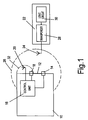
- a protected area 10 is shown schematically, which can be accessed through a door 12.
- the door 12 is secured by means of a lock 14, which can be unlocked by a control unit 16.
- An activator 18, assigned to the door 12, serves to activate the control unit 16, as shall be explained later on.
- An aerial 20 is connected to the control unit and serves to transmit a signal generated by the control unit 16.
- the aerial 20 can also receive a signal transmitted by a remote control unit 22, via an aerial 24, also shown schematically in Fig. 1.
- the large circular arc 26 shown in Fig. 1, schematically indicates the area within which the aerial 24 of the remote control unit 22 must be situated to enable remote control communication between the remote control unit 22 and the control unit 16 within the protected area 10.
- the remote control unit 22 contains a transponder 28 which can receive and transmit signals by way of the aerial 24, as well as a logic circuit 30 to handle signal processing in the remote control unit 22.
- the protected area 10 is a motor vehicle which is accessible through a door 12 that can be locked and unlocked by means of the lock 14.
- the triggering device 18 is the door handle and the aerial 20 is located in an area near the door handle, preferentially in the wing mirror on the side of the driver.
- the remote control unit 22 is housed inside the vehicle key, which also contains a battery that under normal conditions of use provides the necessary energy supply for the desired remote control unit reception range of approximately 1.5 m.
- the vehicle key When the individual in possession of the vehicle key wants to open the door 12, it will be necessary for the individual to approach the vehicle so as to be able to touch the door handle 18 and to move it in a sense as if to open the vehicle. It is then certain that the vehicle key is within the area surrounded by the circular arc 26, that is within range of the remote control 20. Movement of the door handle 18 causes the control unit 16 to transmit an interrogation signal via the aerial 20, which will be received by the aerial 24.
- the interrogation signal contains a specific pulse sequence which enables the transponder 28, in conjunction with the logic circuit 30, to recognise this signal as a signal transmitted by the security system. Any other signal that may be received by chance from any other source will have no effect as far as the remote control unit 22 is concerned.
- the remote control unit 22 transmits an identification code group via the transponder 28 and its associated aerial 24, which is received by the aerial 20 of the control unit 16.
- the control unit 16 compares this identification code group with a code group stored within itself and, if these coincide, generates a switching pulse that is fed to the door lock 14, causing it to unlock.
- the interchange of signals, followed by the unlocking of the lock 14 as a consequence of the switching signal transmitted by the control unit, takes place in such a short time that the individual operating the door handle gains access to the vehicle virtually without delay, provided that the individual is in possession of the correct vehicle key containing the remote control unit 22.
- This authentication process makes sure that only an authorised individual gains access to the vehicle.
- the functional sequence described presupposes that the transmitting range of the remote control unit 22 is sufficiently large to bridge a distance of up to 1.5 m between the aerial 24 and the aerial 20. This will only be possible when the battery within the remote control unit 22 is capable of supplying the necessary energy. If, however, the battery is almost exhausted or completely inactive, the aerial 24 will only transmit a very faint signal, or none at all, as a reaction to the reception of the interrogation signal transmitted by the aerial 20, so that the control unit 16 can no longer recognise the identification code group required for authenticated access through the door 12. In order to enable the authorised individual still to gain access to the vehicle, the remote control unit 22 must be taken into the immediate vicinity of the aerial 20, that is to say into an area indicated by the broken-line circular arc in Fig. 1.
- the transponder 28 housed in the remote control unit is a passive transponder which can generate the supply energy required for its operation and for the operation of the logic circuit 30 from the received interrogation signal. Because of the short distance separating both the aerials 20, 24, it is possible, on the one hand, to transfer sufficient energy by the interrogation signal to the transponder 28 to enable this to generate the required supply energy, and the identification code group, transmitted by the transponder 28 at relatively low power, can then be received by the aerial 20 and further processed as described above, so that authenticated access to the vehicle is made possible once the control unit 16 has verified that the code groups coincide.
- the security system as described therefore always enables an individual authenticated access to the protected area, in this particular case to the vehicle, even when there is no longer any energy supply source available in the remote control unit 22.
- the remote control unit 22 represented in Fig. 2 contains a battery 34 as an energy source, which is connected to a grounded conductor 38 by way of connection 36, whilst its other connection 40 is connected to a supply voltage rail 46 by way of a battery coupling switch 42 and a diode 44.
- the connection 40 of the battery 34 can be connected to the supply voltage either via a low or high-resistance path.
- the receiving element for an interrogation signal transmitted by the control unit within the protected area is a sensor 50, contained in the remote control unit, which consists of a circuit tuned to the frequency of the interrogation signal.
- the inductance of this tuned circuit also constitutes both the transmitting and the receiving aerial of the remote control unit 22.
- the sensor 50 receives an interrogation signal, it outputs an RF signal at its output 52 which can be rectified by the diode 54. This rectified voltage then causes the charging of a capacitor 56, which is connected in parallel with the sensor 50 and the diode 54.
- the output signal of the sensor 50 is also fed to a pulse detector 58, the purpose of which is to output a recognition signal at an output 60 as soon as an RF signal is fed to its input 62 from the sensor.
- the recognition signal from the pulse detector 58 is fed to the remote-field detector 64, which outputs a remote-field signal to the logic circuit 30 whenever the recognition signal is within a pre-determined range.
- a near-field detector 66 Connected to the logic circuit 30 is also a near-field detector 66, which feeds a near-field signal to the logic circuit 30 whenever the charge voltage of the capacitor 56 exceeds a pre-determined threshold value.
- the remote control unit 22 furthermore contains a transmitter unit 68 which is activated by the logic circuit 30 and which may be made to transmit an identification code group stored within it.
- a transmitter unit 68 which is activated by the logic circuit 30 and which may be made to transmit an identification code group stored within it.
- the coil contained in the sensor 50 is used as an aerial.
- the application case to be described assumes that the battery 34 of the remote control unit 22 operates charged to its full capacity, and that an individual wants to gain access to the protected area 10, that is the vehicle in the example described, by means of the remote control unit 22. To this end, the individual, together with remote control unit 22 carried by it, must approach the vehicle to the extent that it is positioned within the area delimited by the circular arc 26. It must furthermore touch the door handle which forms the triggering device 18. This touch contact causes the transmission of a corresponding signal to the control unit 16, which then causes the transmission of the interrogation signal by means of the aerial 20. The interrogation signal is acquired by the sensor 50, so that this, at its output 52, outputs a signal which reaches the pulse detector 58 through its input connection 62.
- the pulse detector 58 receives a small current via the battery coupling switch 42 which is sufficient to cause the pulse detector 58, on recognition of the signal at its input 62, to output a corresponding recognition signal at its output 60.
- the reduced current can flow through the battery coupling switch 42, since this constitutes a relatively high-resistance connection between its connection 40 and the supply voltage rail 46.
- the remote-field detector 64 As soon as the recognition signal at the output 60 of the pulse detector is within the pre-determined range, it is detected by the remote-field detector 64, which then outputs a remote-field signal to the logic circuit 30. In response to the remote-field signal the logic circuit 30 outputs a switching signal to the battery coupling switch 42, thus causing the establishment of a low-resistance path between the connection 40 of the battery 34 and the supply voltage rail. The circuit units contained in the remote control unit 22 are then immediately supplied with the full supply current and therefore become fully operational.
- the interrogation signal which is transmitted by the control unit 16 within the protected area, is not a carrier frequency signal only, but is a pulse modulated signal, that is a carrier signal, containing no-pulse periods that correspond to the information transmitted.
- a differential amplifier 70 fed by a further output signal at an output 108 of the pulse detector 58 and the recognition signal, outputs a square-wave signal derived from the modulated RF signal, which is used by the logic circuit 30 to recognise whether the signal received by the sensor is, in fact, an interrogation signal originating from the control unit of a protected area, or whether it is only an RF signal from other sources.
- the logic circuit 30 As soon as the logic circuit 30 has established that the interrogation signal was, indeed, an interrogation signal transmitted by a control unit 16, it outputs an activation signal from its output 72 which induces the transmitter unit 68 to transmit the identification code group stored in the logic circuit, whereby the coil contained in the sensor 50 acts as a transmission aerial. Since, in the current state of the remote control unit all circuit units are supplied with the full supply current from the battery 34, transmission of the identification code group takes place at relatively high power, so that the relatively large distance present between the sensor 50 and the aerial 20 at the vehicle can be bridged without difficulty. The control unit 16 in the vehicle is therefore able to compare the identification code group with the identification code group stored in it and belonging to the vehicle, and, if both code groups coincide, will generate a signal that unlatches the lock 14, so that the door 12 can be opened.
- the remote control unit 22 will not be able to re-transmit a signal to the control unit 16 within the vehicle, in response to any interrogation signal. It will, therefore, also be impossible to unlock the lock 14 of the door 12.
- the individual carrying the remote control unit 22 is, of course, aware of this and must therefore make use of a further possibility to gain authenticated access to the vehicle.
- the remote control unit must be brought into the immediate proximity of the aerial 20 which, in the example described, is located in the wing mirror on the driver side of the vehicle to be opened.
- the interrogation is caused to be transmitted by the control unit 16.
- This interrogation signal can now be received by the sensor 50, located in close proximity to the aerial 20.
- the remote control unit 22 will now operate in its intended passive transponder mode. This means, in the first instance, that the interrogation signal received is rectified by the diode 54, so that the rectified voltage will charge up the capacitor 56.
- the charging voltage at this capacitor 56 now provides the supply energy for the entire remote control unit 22.
- the capacitor 56 in relation to the energy supplied by the transmitted interrogation signal, is dimensioned so that the energy stored in it is sufficient to effect the transmission of the identification code group, assisted by signals from the pulse detector 58, the remote-field detector 64 and the logic circuit 30, taking into consideration the transmitter unit 68.
- transmission of this identification code group is at low power, as a result of the short distance separating the aerial 24 of the remote control unit 22 and the aerial 20 at the vehicle, it will be sufficient for the control unit 16 to verify the identification code group and, if coincidence is established, to unlock the lock 14 and enable access to the vehicle, in the same way as in the previously described case where the battery 34 was operational. In this way, it is made possible for the individual to gain authenticated access to the vehicle even if the battery is inactive.
- a near-field detector 66 is provided in the remote control unit 22, which fulfils the function to be described in the following.
- the sensor 50 receives such an amount of energy that the capacitor 56 can charge up to a voltage which is higher than the supply voltage provided by the battery 34.
- the near-field detector 66 ascertains that the charge voltage of the capacitor 56 exceeds the threshold value corresponding to the maximum supply voltage provided by the battery and outputs a near-field signal to the logic circuit 30, which causes the battery coupling switch 42 once again to abandon its low-resistance mode, leaving only the high-resistance connection path open.
- the energy drain from the battery 34 is therefore very much reduced in this particular case, which results in an extension of the active life of the battery.
- Fig. 3 represents the circuit arrangement of the sensor 50.
- the sensor contains a coil 74 which fulfils the function of the aerial 24 of the remote control unit 22.
- the sensor contains a capacitor 76 which, in conjunction with the coil 74, forms a resonant circuit tuned to the frequency of the interrogation signal transmitted by the control unit 16.
- Connection 78 of the sensor 80 is connected to the ground rail 38, the connection 80 is connected to the transmitter unit 68, and the connection 52 is connected to the input 62 of the pulse detector 58.
- Fig. 4 represents the circuit arrangement of the battery coupling switch 42. It contains a MOS field-effect transistor 82 whose source-drain path establishes a connection from the battery connection 40 to the diode 44. It furthermore contains a resistor 84 which is connected between the gate and the drain connections of the MOS field-effect transistor 82. In the normal quiescent state of the circuit, the MOS field-effect transistor 82 is in a high-resistance state, where only a small current can flow through its source-drain path.
- the logic circuit 30 sends a switching signal to the connection 83 of the battery coupling switch 42, the MOS field-effect transistor 82 will be put into its conducting state, so that a low-resistance path is made available between the battery connection 40 and, via the diode 44, the supply voltage rail 46.
- This state only obtains when the pulse detector 58 has detected the reception of an interrogation signal by the sensor 50, and the remote-field detector 64 supplies the remote-field signal to the logic circuit 30 and, furthermore, the near-field detector 66 has not registered a voltage at the capacitor 56 that exceeds the battery supply voltage.
- This pulse detector 58 must be equipped in such a way as to be in a position, even in the quiescent standby mode of the remote control unit 22, that is in a state when current consumption is very low or even where the battery has become inactive, to react to an interrogation signal received by the sensor and, if applicable, generate a recognition signal at the output 60.
- Fig. 5 illustrates a possible embodiment of this pulse detector 58.
- the pulse detector 58 comprises two current mirrors, each consisting of two bipolar transistors 86, 88 and 90, 92 respectively. These current mirrors are interconnected in such a way as to form together an amplifier.
- the emitter of the transistor 90 forms the input 62 connected to the sensor, whilst the emitter of the transistor 92 is connected to the ground rail 38.
- the interconnected emitters of the transistors 86 and 88 are connected to the supply rail.
- the collectors of the transistors 86 and 90 are connected to each other, whilst the interconnection between the collectors of transistors 88 and 92 is via a MOS field-effect transistor 94, which could also be replaced by a resistor and merely behaves like a current source.
- the output signals of the amplifier formed by the two current mirrors are taken from the circuit points 96 and 98 and fed to a differential amplifier 100.
- the negative feedback provided at the differential amplifier 100 by two diodes in series with a resistor 102 serves to limit the dynamic range.
- the pulse detector 58 outputs the recognition signal at its output 60, and a reference signal for the amplifier 70 at a further output 108.
- the battery 34 is capable of supplying the full supply voltage and that the remote control unit 22 is in a quiescent state, in that the field-effect transistor 82 in the battery coupling switch 42 is in the off-state. Only a very low voltage therefore exists between the ground rail 38 and the supply rail 46.
- the base-emitter area of the transistor 86 is made larger than that of the transistor 88, with the consequence that a lower voltage obtains at the collector of the transistor 86 than at the collector of transistor 88.
- the remote-field detector 64 reacts to this signal by not outputting a remote-field signal.
- a radio frequency signal reaches input 62 of the pulse detector 58 which, via the transistor 90 and in the present state of the pulse detector 58, causes the voltage at the circuit point 96 to rise so as to exceed the voltage at the circuit point 98.
- the voltage difference between the circuit points 96 and 98 thereby becomes virtually inverted, so that a signal of low value is produced at the output of the differential amplifier 100.
- This signal causes the remote-field detector 64 to output a remote-field signal to the logic circuit 30.
- the transistor 82 in the battery coupling switch 42 is put into the conducting state, so that now the full supply voltage is able to reach the supply voltage rail 46.
- the differential amplifier 70 receives at one of its inputs the recognition signal from the output 60 of the pulse detector 58, and at the other input the voltage present at the output 108 of the pulse detector, which is used as a reference voltage.
- the reference voltage at output 108 is a reference voltage which changes dynamically with the available supply voltage, and which is always kept in the correct relation to the voltage at output 60.
- the interrogation signal is not a continuous radio frequency signal, but rather a keyed signal composed of RF pulses and no-pulse periods
- the differential amplifier 70 will output at its output either a high or a low level signal, depending on whether the RF pulse is present or not. From the sequence of high and low level signals, the logic circuit 30 can ascertain whether the interrogation signal is, in fact, a signal transmitted for the benefit of the remote control unit 22, or whether it is an RF signal emanating from some other source.
- the pulse detector 58 even at this stage, is able to output a defined recognition signal from its output 60, which can then be further processed by the other circuit units within the remote control unit 22 as soon as the charging voltage at the capacitor 56 has reached its full value, just as in the case of a functional battery 34.
- the pulse detector 58 described therefore makes it possible to recognise and evaluate an interrogation signal received by the sensor 50, with or without a functionally operative battery 34.
Landscapes
- Engineering & Computer Science (AREA)
- Mechanical Engineering (AREA)
- Computer Networks & Wireless Communication (AREA)
- Physics & Mathematics (AREA)
- General Physics & Mathematics (AREA)
- Lock And Its Accessories (AREA)
- Selective Calling Equipment (AREA)
Claims (6)
- Système de sécurité permettant un accès authentifié d'un individu à une zone protégée au moyen d'une unité de télécommande, portée par l'individu, contenant un transpondeur qui, lors de la réception d'un signal d'interrogation, émet un groupe de code d'identification, et d'une unité de commande, située à l'intérieur de la zone protégée, qui, lorsqu'elle est activée par l'individu, émet le signal d'interrogation et vérifie ensuite le groupe de code d'identification envoyé par le transpondeur, en permettant l'accès de l'individu à la zone protégée seulement après une vérification positive de l'autorisation d'accès, caractérisé en ce que le transpondeur (28) contenu dans l'unité de télécommande (22) est un transpondeur passif qui obtient une tension d'alimentation à partir du signal d'interrogation émis par l'unité de commande (16) et la délivre dans un rail d'alimentation (46), dans lequel l'unité de télécommande (22) contient une batterie (34) qui, à l'aide d'un commutateur de couplage de batterie contrôlable (42), peut être reliée au rail d'alimentation (46) par l'intermédiaire d'un chemin à résistance élevée lorsque l'unité de télécommande (22) se trouve dans un état au repos, ou par l'intermédiaire d'un chemin à résistance faible lorsque l'unité de télécommande se trouve dans son état de fonctionnement, dans lequel il est fourni un détecteur d'impulsion (58) qui reçoit sa tension d'alimentation par l'intermédiaire du chemin à résistance élevée du commutateur de couplage de batterie (42) lorsque l'unité de télécommande (22) se trouve dans son état au repos, et qui, lors de la réception du signal d'interrogation en provenance du transpondeur (28), délivre en sortie un signal de reconnaissance, dans lequel il est fourni un détecteur de champ distant (64) qui reçoit le signal de reconnaissance et délivre en sortie un signal de champ distant dès que la valeur du signal de reconnaissance se situe à l'intérieur d'une plage prédéterminée, dans lequel il est fourni un circuit logique (30) qui, lors de la réception du signal de champ distant, délivre en sortie un signal de commutation au commutateur de couplage de batterie (42) qui le commute dans l'état où la batterie (34) est reliée au rail d'alimentation (46) par l'intermédiaire du chemin à résistance faible, et délivre un signal d'activation au transpondeur (28) qui provoque l'émission, par son unité d'émission (68), du groupe de code d'identification, et dans lequel il est fourni un détecteur de champ proche (66) qui, lors de la reconnaissance d'une valeur de la tension d'alimentation produite par le transpondeur (28) qui dépasse une valeur de seuil prédéterminée, délivre en sortie un signal de champ proche qui fait mettre par le circuit logique (30), le commutateur de couplage de batterie (42), dans l'état qui prévaut à l'état de repos de l'unité de télécommande (22), et émettre le signal d'activation vers le transpondeur (28).
- Système de sécurité selon la revendication 1, caractérisé en ce que la zone protégée (10) est un véhicule dont la porte (12) ne sera déverrouillée par l'unité de commande (16) logée dans ce véhicule, que lorsque le groupe de code d'identification renvoyé par le transpondeur (28) correspond au groupe de code attendu par l'unité de commande (16).
- Système de sécurité selon la revendication 2, caractérisé en ce que l'unité de commande (16) logée dans le véhicule, émet le signal d'interrogation lorsque l'individu touche ou actionne la poignée de porte (18) du véhicule.
- Système de sécurité selon l'une quelconque des revendications 2 ou 3, caractérisé en ce qu'une antenne (20), faisant partie de l'unité de commande du véhicule (16), est logée dans le rétroviseur extérieur du côté du conducteur.
- Système de sécurité selon l'une quelconque des revendications précédentes, caractérisé en ce que le détecteur d'impulsions (58) comprend un premier et un second circuits miroirs de courant, chacun d'eux se composant de transistors dont les bases sont reliées (90, 92, 86, 88), qui sont interconnectés de façon à former un circuit d'amplification, grâce à quoi le collecteur du premier transistor (90) du premier circuit miroir de courant est connecté au collecteur du premier transistor (86) du second circuit miroir de courant, et le collecteur du second transistor (92) du premier circuit miroir de courant est connecté au collecteur du second transistor (88) du second circuit miroir de courant par l'intermédiaire d'une source de courant (94), grâce à quoi les transistors (86, 88) du second circuit miroir de courant, afin de fournir des tensions de sortie différenciées nettement pour des courants de collecteur identiques au niveau de leurs collecteurs respectifs, comprennent des zones base-émetteur dimensionnées différemment, de sorte que le signal d'interrogation reçu en provenance du transpondeur (28) soit appliqué à l'émetteur du premier transistor (90) du premier circuit miroir de courant, et qu'il soit fourni un amplificateur différentiel (100) qui comporte des entrées, dont l'une est reliée aux collecteurs interconnectés des premiers transistors (90, 86) des deux circuits miroirs de courant, et l'autre est reliée au collecteur du second transistor (88) du second circuit miroir de courant, grâce à quoi le signal délivré en sortie de l'amplificateur différentiel (100) est le signal de reconnaissance.
- Système de sécurité selon la revendication 5, caractérisé en ce que l'amplificateur différentiel (100) est muni d'une contre-réaction au moyen de deux diodes (104, 106) et d'une résistance (102), afin de limiter la plage dynamique.
Applications Claiming Priority (2)
| Application Number | Priority Date | Filing Date | Title |
|---|---|---|---|
| DE10012637 | 2000-03-15 | ||
| DE10012637A DE10012637B4 (de) | 2000-03-15 | 2000-03-15 | Sicherheitssystem zur Ermöglichung des authentifizierten Zugangs eines Individuums zu einem geschützten Bereich |
Publications (3)
| Publication Number | Publication Date |
|---|---|
| EP1134134A2 EP1134134A2 (fr) | 2001-09-19 |
| EP1134134A3 EP1134134A3 (fr) | 2004-01-02 |
| EP1134134B1 true EP1134134B1 (fr) | 2006-06-28 |
Family
ID=7634828
Family Applications (1)
| Application Number | Title | Priority Date | Filing Date |
|---|---|---|---|
| EP01105469A Expired - Lifetime EP1134134B1 (fr) | 2000-03-15 | 2001-03-14 | Système de sécurité permettant l'accès authentifié d'un individu à une enceinte protégée |
Country Status (4)
| Country | Link |
|---|---|
| US (1) | US6690259B2 (fr) |
| EP (1) | EP1134134B1 (fr) |
| JP (1) | JP2002053009A (fr) |
| DE (2) | DE10012637B4 (fr) |
Families Citing this family (33)
| Publication number | Priority date | Publication date | Assignee | Title |
|---|---|---|---|---|
| DE10019442C2 (de) | 2000-04-19 | 2002-05-08 | Texas Instruments Deutschland | Sicherheitssystem zum Verhindern des unbefugten Startens des Motors eines Fahrzeugs |
| US20030216817A1 (en) * | 2002-05-16 | 2003-11-20 | Richard Pudney | Vehicle access system with sensor |
| DE10306689A1 (de) | 2003-02-11 | 2004-08-19 | Atmel Germany Gmbh | Schaltungsanordnung zur Signaldetektion |
| DE10320255A1 (de) * | 2003-05-07 | 2004-11-25 | Daimlerchrysler Ag | Zugangsberechtigungssystem für Fahrzeuge mit wenigstens einem Keyless-Go-Schlüssel |
| DE10320786A1 (de) * | 2003-05-09 | 2004-12-02 | Hella Kgaa Hueck & Co. | Authentifikationsvorrichtung für ein Kraftfahrzeug |
| US20040228168A1 (en) * | 2003-05-13 | 2004-11-18 | Richard Ferrant | Semiconductor memory device and method of operating same |
| WO2004114240A2 (fr) * | 2003-06-13 | 2004-12-29 | Xtec, Incorporated | Lecteur differentiel d'identification de frequences hertziennes |
| US7868745B2 (en) * | 2004-06-25 | 2011-01-11 | Lear Corporation | Integrated passive entry transmitter/receiver |
| US9007195B2 (en) * | 2004-06-25 | 2015-04-14 | Lear Corporation | Remote FOB integrated in a personal convenience device |
| US7446644B2 (en) * | 2005-01-14 | 2008-11-04 | Secureall Corporation | Universal hands free key and lock system |
| DE102005003488B4 (de) * | 2005-01-25 | 2009-03-19 | Sick Ag | Kapzitiver Sensor und Überwachungsverfahren |
| TWI322384B (en) * | 2005-03-07 | 2010-03-21 | Compal Electronics Inc | Radio frequency identification monitor system and method |
| US20090322490A1 (en) * | 2005-03-07 | 2009-12-31 | Compal Electronics, Inc. | Radio frequency identification monitoring system and method |
| US8970346B2 (en) * | 2005-05-20 | 2015-03-03 | Continental Automotive Systems, Inc. | Signal sensitivity control during passive authentication |
| JP4140731B2 (ja) * | 2005-07-08 | 2008-08-27 | 三菱電機株式会社 | 車両用通信装置 |
| CN1905747B (zh) * | 2005-07-28 | 2012-06-20 | 因温特奥股份公司 | 在环境中特别是在建筑物中引导使用者的方法 |
| JP2007243490A (ja) * | 2006-03-07 | 2007-09-20 | Teruya:Kk | ハイブリッド型移動体センシング通信システム |
| KR101435966B1 (ko) * | 2006-05-31 | 2014-08-29 | 가부시키가이샤 한도오따이 에네루기 켄큐쇼 | 반도체 장치 및 상기 반도체 장치를 가진 ic 라벨, ic 태그, 및 ic 카드 |
| US20120126948A1 (en) * | 2006-11-20 | 2012-05-24 | Kevin Michael Brunski | Identification system and method |
| US10128893B2 (en) | 2008-07-09 | 2018-11-13 | Secureall Corporation | Method and system for planar, multi-function, multi-power sourced, long battery life radio communication appliance |
| US9642089B2 (en) | 2008-07-09 | 2017-05-02 | Secureall Corporation | Method and system for planar, multi-function, multi-power sourced, long battery life radio communication appliance |
| US11469789B2 (en) | 2008-07-09 | 2022-10-11 | Secureall Corporation | Methods and systems for comprehensive security-lockdown |
| US10447334B2 (en) | 2008-07-09 | 2019-10-15 | Secureall Corporation | Methods and systems for comprehensive security-lockdown |
| US8224313B2 (en) * | 2008-09-24 | 2012-07-17 | Centurylink Intellectual Property Llc | System and method for controlling vehicle systems from a cell phone |
| US8126450B2 (en) * | 2008-09-24 | 2012-02-28 | Embarq Holdings Company Llc | System and method for key free access to a vehicle |
| US8819182B2 (en) * | 2008-09-24 | 2014-08-26 | Centurylink Intellectual Property Llc | System and method for updating vehicle media content |
| KR101824503B1 (ko) * | 2011-03-09 | 2018-02-01 | 삼성전자 주식회사 | 저전력 무선 통신 장치 |
| KR101830960B1 (ko) | 2011-08-18 | 2018-02-22 | 삼성전자주식회사 | 휴대용 단말기의 일체형으로 구비된 엔에프시 안테나와 비접촉 충전 코일의 구분 장치 및 그 방법 |
| US20140049367A1 (en) * | 2012-08-16 | 2014-02-20 | Schlage Lock Company Llc | Automatic unlock device and method |
| TWI633026B (zh) * | 2014-09-11 | 2018-08-21 | 鴻海精密工業股份有限公司 | 車輛防盜系統及其防盜方法 |
| US10033213B2 (en) * | 2014-09-30 | 2018-07-24 | Johnson Controls Technology Company | Short circuit wake-up system and method for automotive battery while in key-off position |
| DE102016005342A1 (de) * | 2015-05-04 | 2016-11-10 | Marquardt Gmbh | Schließsystem sowie Vorrichtung mit einem Schließsystem |
| US10362350B2 (en) | 2016-04-28 | 2019-07-23 | Ecolink Intelligent Technology, Inc. | Systems, methods and apparatus for interacting with a security system using a television remote control |
Family Cites Families (7)
| Publication number | Priority date | Publication date | Assignee | Title |
|---|---|---|---|---|
| DE3788348T2 (de) * | 1987-07-31 | 1994-03-17 | Texas Instruments Deutschland | Transponder-Anordnung. |
| DE69202281T2 (de) * | 1991-03-06 | 1995-09-07 | Delco Electronics Corp | Fernbetätigungssystem zum Regeln einer Funktion einer Basisstation. |
| DE4329697C2 (de) * | 1993-09-02 | 1995-10-05 | Siemens Ag | Fernsteuerbare Zugangskontrolleinrichtung |
| US5541585A (en) * | 1994-10-11 | 1996-07-30 | Stanley Home Automation | Security system for controlling building access |
| US6034603A (en) * | 1997-01-24 | 2000-03-07 | Axcess, Inc. | Radio tag system and method with improved tag interference avoidance |
| DE19817577C2 (de) * | 1997-12-10 | 2000-04-13 | Delphi Automotive Systems Gmbh | Vorrichtung und Verfahren zur Zugangsberechtigungsprüfung |
| US6034617A (en) * | 1998-12-04 | 2000-03-07 | Eaton Corporation | Operator intent based passive keyless vehicle control system |
-
2000
- 2000-03-15 DE DE10012637A patent/DE10012637B4/de not_active Expired - Fee Related
-
2001
- 2001-03-14 EP EP01105469A patent/EP1134134B1/fr not_active Expired - Lifetime
- 2001-03-14 DE DE60121081T patent/DE60121081T2/de not_active Expired - Lifetime
- 2001-03-14 US US09/808,527 patent/US6690259B2/en not_active Expired - Lifetime
- 2001-03-15 JP JP2001121756A patent/JP2002053009A/ja not_active Abandoned
Also Published As
| Publication number | Publication date |
|---|---|
| EP1134134A3 (fr) | 2004-01-02 |
| US6690259B2 (en) | 2004-02-10 |
| DE10012637B4 (de) | 2005-09-01 |
| JP2002053009A (ja) | 2002-02-19 |
| DE60121081T2 (de) | 2006-12-21 |
| US20020130763A1 (en) | 2002-09-19 |
| DE10012637A1 (de) | 2001-09-27 |
| EP1134134A2 (fr) | 2001-09-19 |
| DE60121081D1 (de) | 2006-08-10 |
Similar Documents
| Publication | Publication Date | Title |
|---|---|---|
| EP1134134B1 (fr) | Système de sécurité permettant l'accès authentifié d'un individu à une enceinte protégée | |
| US6323566B1 (en) | Transponder for remote keyless entry systems | |
| EP0848123B1 (fr) | Système télécommandé d'entrée sans clé | |
| US6992565B1 (en) | Electronic communications system | |
| EP0892134B1 (fr) | Dispositif de verrouillage pour vehicules | |
| US7181189B2 (en) | Vehicular remote control system and tire pressure monitoring system | |
| US5552641A (en) | Remote-control access control device and method for operating the same | |
| US6963794B2 (en) | Locking system for a motor vehicle | |
| US6127922A (en) | Vehicle security system with remote systems control | |
| US7305284B2 (en) | Remote control system and method for vehicle | |
| JP2001354117A (ja) | 非認定者が車両のエンジンを起動するのを防ぐ保護システム | |
| US7612649B2 (en) | Smart entry system | |
| US20060012462A1 (en) | Remote control system | |
| US8179230B2 (en) | Method for passive keyless entry of a motor vehicle especially of an industrial vehicle | |
| US8193945B2 (en) | System and method for remote activation using a transmitter switch array | |
| JP3812291B2 (ja) | 移動体用機器遠隔制御装置及び移動体用携帯機 | |
| JP4952358B2 (ja) | 車両用ユーザー照合システム | |
| JPH1025939A (ja) | 車両用ドアロック装置の制御装置 | |
| JP3720308B2 (ja) | 車載機器遠隔制御システム | |
| US20100039222A1 (en) | Keyless access system and method for a truck and truck equipped with such a system | |
| JPH10153025A (ja) | 車両用ドアロックシステム | |
| JP3783905B2 (ja) | リモートコントロール用送受信装置、及び車両用ワイヤレスドアロック制御装置 | |
| JPH09105254A (ja) | リモートコントロールシステム | |
| JPH09104297A (ja) | 車両用負荷制御システム | |
| KR20010056453A (ko) | 차량의 카드키형 도어잠금장치 및 방법 |
Legal Events
| Date | Code | Title | Description |
|---|---|---|---|
| PUAI | Public reference made under article 153(3) epc to a published international application that has entered the european phase |
Free format text: ORIGINAL CODE: 0009012 |
|
| AK | Designated contracting states |
Kind code of ref document: A2 Designated state(s): AT BE CH CY DE DK ES FI FR GB GR IE IT LI LU MC NL PT SE TR |
|
| AX | Request for extension of the european patent |
Free format text: AL;LT;LV;MK;RO;SI |
|
| PUAL | Search report despatched |
Free format text: ORIGINAL CODE: 0009013 |
|
| AK | Designated contracting states |
Kind code of ref document: A3 Designated state(s): AT BE CH CY DE DK ES FI FR GB GR IE IT LI LU MC NL PT SE TR |
|
| AX | Request for extension of the european patent |
Extension state: AL LT LV MK RO SI |
|
| RIC1 | Information provided on ipc code assigned before grant |
Ipc: 7G 07C 9/00 A Ipc: 7E 05B 49/00 B Ipc: 7B 60R 25/00 B |
|
| 17P | Request for examination filed |
Effective date: 20040525 |
|
| AKX | Designation fees paid |
Designated state(s): DE FR GB |
|
| GRAP | Despatch of communication of intention to grant a patent |
Free format text: ORIGINAL CODE: EPIDOSNIGR1 |
|
| GRAS | Grant fee paid |
Free format text: ORIGINAL CODE: EPIDOSNIGR3 |
|
| GRAA | (expected) grant |
Free format text: ORIGINAL CODE: 0009210 |
|
| AK | Designated contracting states |
Kind code of ref document: B1 Designated state(s): DE FR GB |
|
| REG | Reference to a national code |
Ref country code: GB Ref legal event code: FG4D |
|
| REF | Corresponds to: |
Ref document number: 60121081 Country of ref document: DE Date of ref document: 20060810 Kind code of ref document: P |
|
| ET | Fr: translation filed | ||
| PLBE | No opposition filed within time limit |
Free format text: ORIGINAL CODE: 0009261 |
|
| STAA | Information on the status of an ep patent application or granted ep patent |
Free format text: STATUS: NO OPPOSITION FILED WITHIN TIME LIMIT |
|
| 26N | No opposition filed |
Effective date: 20070329 |
|
| REG | Reference to a national code |
Ref country code: FR Ref legal event code: PLFP Year of fee payment: 16 |
|
| REG | Reference to a national code |
Ref country code: FR Ref legal event code: PLFP Year of fee payment: 17 |
|
| REG | Reference to a national code |
Ref country code: FR Ref legal event code: PLFP Year of fee payment: 18 |
|
| PGFP | Annual fee paid to national office [announced via postgrant information from national office to epo] |
Ref country code: DE Payment date: 20190215 Year of fee payment: 19 Ref country code: GB Payment date: 20190227 Year of fee payment: 19 |
|
| PGFP | Annual fee paid to national office [announced via postgrant information from national office to epo] |
Ref country code: FR Payment date: 20190220 Year of fee payment: 19 |
|
| REG | Reference to a national code |
Ref country code: DE Ref legal event code: R119 Ref document number: 60121081 Country of ref document: DE |
|
| PG25 | Lapsed in a contracting state [announced via postgrant information from national office to epo] |
Ref country code: DE Free format text: LAPSE BECAUSE OF NON-PAYMENT OF DUE FEES Effective date: 20201001 Ref country code: FR Free format text: LAPSE BECAUSE OF NON-PAYMENT OF DUE FEES Effective date: 20200331 |
|
| GBPC | Gb: european patent ceased through non-payment of renewal fee |
Effective date: 20200314 |
|
| PG25 | Lapsed in a contracting state [announced via postgrant information from national office to epo] |
Ref country code: GB Free format text: LAPSE BECAUSE OF NON-PAYMENT OF DUE FEES Effective date: 20200314 |