EP1136749A1 - Illumination device - Google Patents
Illumination device Download PDFInfo
- Publication number
- EP1136749A1 EP1136749A1 EP00963046A EP00963046A EP1136749A1 EP 1136749 A1 EP1136749 A1 EP 1136749A1 EP 00963046 A EP00963046 A EP 00963046A EP 00963046 A EP00963046 A EP 00963046A EP 1136749 A1 EP1136749 A1 EP 1136749A1
- Authority
- EP
- European Patent Office
- Prior art keywords
- lamp
- discharge lamp
- lamp body
- lighting device
- block member
- Prior art date
- Legal status (The legal status is an assumption and is not a legal conclusion. Google has not performed a legal analysis and makes no representation as to the accuracy of the status listed.)
- Withdrawn
Links
- 238000005286 illumination Methods 0.000 title abstract 2
- 239000002184 metal Substances 0.000 claims description 14
- 230000000903 blocking effect Effects 0.000 claims description 10
- 238000007789 sealing Methods 0.000 claims description 4
- 239000011347 resin Substances 0.000 claims description 3
- 229920005989 resin Polymers 0.000 claims description 3
- 239000000463 material Substances 0.000 claims description 2
- 230000000694 effects Effects 0.000 description 7
- 238000005192 partition Methods 0.000 description 7
- 230000002093 peripheral effect Effects 0.000 description 7
- 230000009467 reduction Effects 0.000 description 7
- 230000007246 mechanism Effects 0.000 description 3
- 238000004078 waterproofing Methods 0.000 description 3
- 230000004048 modification Effects 0.000 description 2
- 238000012986 modification Methods 0.000 description 2
- 239000000758 substrate Substances 0.000 description 2
- 239000000853 adhesive Substances 0.000 description 1
- 230000001070 adhesive effect Effects 0.000 description 1
- 239000002390 adhesive tape Substances 0.000 description 1
- 230000004075 alteration Effects 0.000 description 1
- 230000008878 coupling Effects 0.000 description 1
- 238000010168 coupling process Methods 0.000 description 1
- 238000005859 coupling reaction Methods 0.000 description 1
- 239000011521 glass Substances 0.000 description 1
- 229910001507 metal halide Inorganic materials 0.000 description 1
- 150000005309 metal halides Chemical class 0.000 description 1
- 238000012856 packing Methods 0.000 description 1
- 230000005855 radiation Effects 0.000 description 1
Images





Classifications
-
- H—ELECTRICITY
- H05—ELECTRIC TECHNIQUES NOT OTHERWISE PROVIDED FOR
- H05B—ELECTRIC HEATING; ELECTRIC LIGHT SOURCES NOT OTHERWISE PROVIDED FOR; CIRCUIT ARRANGEMENTS FOR ELECTRIC LIGHT SOURCES, IN GENERAL
- H05B41/00—Circuit arrangements or apparatus for igniting or operating discharge lamps
- H05B41/14—Circuit arrangements
- H05B41/26—Circuit arrangements in which the lamp is fed by power derived from DC by means of a converter, e.g. by high-voltage DC
- H05B41/28—Circuit arrangements in which the lamp is fed by power derived from DC by means of a converter, e.g. by high-voltage DC using static converters
- H05B41/288—Circuit arrangements in which the lamp is fed by power derived from DC by means of a converter, e.g. by high-voltage DC using static converters with semiconductor devices and specially adapted for lamps without preheating electrodes, e.g. for high-intensity discharge lamps, high-pressure mercury or sodium lamps or low-pressure sodium lamps
- H05B41/292—Arrangements for protecting lamps or circuits against abnormal operating conditions
- H05B41/2921—Arrangements for protecting lamps or circuits against abnormal operating conditions for protecting the circuit against abnormal operating conditions
-
- B—PERFORMING OPERATIONS; TRANSPORTING
- B60—VEHICLES IN GENERAL
- B60Q—ARRANGEMENT OF SIGNALLING OR LIGHTING DEVICES, THE MOUNTING OR SUPPORTING THEREOF OR CIRCUITS THEREFOR, FOR VEHICLES IN GENERAL
- B60Q1/00—Arrangement of optical signalling or lighting devices, the mounting or supporting thereof or circuits therefor
- B60Q1/0064—Arrangement of optical signalling or lighting devices, the mounting or supporting thereof or circuits therefor with provision for maintenance, e.g. changing the light bulb
- B60Q1/007—Arrangement of optical signalling or lighting devices, the mounting or supporting thereof or circuits therefor with provision for maintenance, e.g. changing the light bulb via a removable cap
-
- B—PERFORMING OPERATIONS; TRANSPORTING
- B60—VEHICLES IN GENERAL
- B60Q—ARRANGEMENT OF SIGNALLING OR LIGHTING DEVICES, THE MOUNTING OR SUPPORTING THEREOF OR CIRCUITS THEREFOR, FOR VEHICLES IN GENERAL
- B60Q1/00—Arrangement of optical signalling or lighting devices, the mounting or supporting thereof or circuits therefor
- B60Q1/0088—Details of electrical connections
- B60Q1/0094—Arrangement of electronic circuits separated from the light source, e.g. mounting of housings for starter circuits for discharge lamps
-
- F—MECHANICAL ENGINEERING; LIGHTING; HEATING; WEAPONS; BLASTING
- F21—LIGHTING
- F21S—NON-PORTABLE LIGHTING DEVICES; SYSTEMS THEREOF; VEHICLE LIGHTING DEVICES SPECIALLY ADAPTED FOR VEHICLE EXTERIORS
- F21S41/00—Illuminating devices specially adapted for vehicle exteriors, e.g. headlamps
- F21S41/10—Illuminating devices specially adapted for vehicle exteriors, e.g. headlamps characterised by the light source
- F21S41/14—Illuminating devices specially adapted for vehicle exteriors, e.g. headlamps characterised by the light source characterised by the type of light source
- F21S41/17—Discharge light sources
- F21S41/172—High-intensity discharge light sources
-
- F—MECHANICAL ENGINEERING; LIGHTING; HEATING; WEAPONS; BLASTING
- F21—LIGHTING
- F21S—NON-PORTABLE LIGHTING DEVICES; SYSTEMS THEREOF; VEHICLE LIGHTING DEVICES SPECIALLY ADAPTED FOR VEHICLE EXTERIORS
- F21S41/00—Illuminating devices specially adapted for vehicle exteriors, e.g. headlamps
- F21S41/10—Illuminating devices specially adapted for vehicle exteriors, e.g. headlamps characterised by the light source
- F21S41/19—Attachment of light sources or lamp holders
- F21S41/192—Details of lamp holders, terminals or connectors
-
- F—MECHANICAL ENGINEERING; LIGHTING; HEATING; WEAPONS; BLASTING
- F21—LIGHTING
- F21V—FUNCTIONAL FEATURES OR DETAILS OF LIGHTING DEVICES OR SYSTEMS THEREOF; STRUCTURAL COMBINATIONS OF LIGHTING DEVICES WITH OTHER ARTICLES, NOT OTHERWISE PROVIDED FOR
- F21V23/00—Arrangement of electric circuit elements in or on lighting devices
-
- F—MECHANICAL ENGINEERING; LIGHTING; HEATING; WEAPONS; BLASTING
- F21—LIGHTING
- F21V—FUNCTIONAL FEATURES OR DETAILS OF LIGHTING DEVICES OR SYSTEMS THEREOF; STRUCTURAL COMBINATIONS OF LIGHTING DEVICES WITH OTHER ARTICLES, NOT OTHERWISE PROVIDED FOR
- F21V23/00—Arrangement of electric circuit elements in or on lighting devices
- F21V23/02—Arrangement of electric circuit elements in or on lighting devices the elements being transformers, impedances or power supply units, e.g. a transformer with a rectifier
- F21V23/026—Fastening of transformers or ballasts
-
- F—MECHANICAL ENGINEERING; LIGHTING; HEATING; WEAPONS; BLASTING
- F21—LIGHTING
- F21V—FUNCTIONAL FEATURES OR DETAILS OF LIGHTING DEVICES OR SYSTEMS THEREOF; STRUCTURAL COMBINATIONS OF LIGHTING DEVICES WITH OTHER ARTICLES, NOT OTHERWISE PROVIDED FOR
- F21V31/00—Gas-tight or water-tight arrangements
-
- H—ELECTRICITY
- H05—ELECTRIC TECHNIQUES NOT OTHERWISE PROVIDED FOR
- H05B—ELECTRIC HEATING; ELECTRIC LIGHT SOURCES NOT OTHERWISE PROVIDED FOR; CIRCUIT ARRANGEMENTS FOR ELECTRIC LIGHT SOURCES, IN GENERAL
- H05B41/00—Circuit arrangements or apparatus for igniting or operating discharge lamps
-
- H—ELECTRICITY
- H05—ELECTRIC TECHNIQUES NOT OTHERWISE PROVIDED FOR
- H05B—ELECTRIC HEATING; ELECTRIC LIGHT SOURCES NOT OTHERWISE PROVIDED FOR; CIRCUIT ARRANGEMENTS FOR ELECTRIC LIGHT SOURCES, IN GENERAL
- H05B41/00—Circuit arrangements or apparatus for igniting or operating discharge lamps
- H05B41/02—Details
- H05B41/04—Starting switches
- H05B41/042—Starting switches using semiconductor devices
-
- F—MECHANICAL ENGINEERING; LIGHTING; HEATING; WEAPONS; BLASTING
- F21—LIGHTING
- F21S—NON-PORTABLE LIGHTING DEVICES; SYSTEMS THEREOF; VEHICLE LIGHTING DEVICES SPECIALLY ADAPTED FOR VEHICLE EXTERIORS
- F21S41/00—Illuminating devices specially adapted for vehicle exteriors, e.g. headlamps
- F21S41/50—Illuminating devices specially adapted for vehicle exteriors, e.g. headlamps characterised by aesthetic components not otherwise provided for, e.g. decorative trim, partition walls or covers
- F21S41/55—Attachment thereof
-
- F—MECHANICAL ENGINEERING; LIGHTING; HEATING; WEAPONS; BLASTING
- F21—LIGHTING
- F21W—INDEXING SCHEME ASSOCIATED WITH SUBCLASSES F21K, F21L, F21S and F21V, RELATING TO USES OR APPLICATIONS OF LIGHTING DEVICES OR SYSTEMS
- F21W2102/00—Exterior vehicle lighting devices for illuminating purposes
Definitions
- This invention relates to luminaires, for example, a luminaire employed in automotive head lamp.
- U.S. Patent No. 6,066,921 has been assigned to the same assignee as the assignee of the present application, and its luminaire comprises a lamp including a discharge lamp, socket, reflector, lamp cover, lens and lamp body, a lighting device including an inverter and igniter, and a coupler, wherein the socket connected through cables to the lighting device is inserted in the lamp.
- the present invention is to overcome the foregoing problems, and its object is to provide a luminaire which can reduce the length of such part to which the high voltage is applied as the harness employed in the lighting circuit, and which can attain an excellent startability.
- the luminaire according to the present invention is characterized in comprising a discharge lamp, a lighting device for supplying a power for lighting the discharge lamp, an igniter for starting the discharge lamp, and a lamp body having at least a discharge-lamp holding member and housing the discharge lamp, wherein the lighting device and igniter are provided as separated, the lighting device is provided in the lamp body, and the igniter is provided adjacent to the discharge lamp.
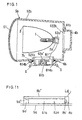
- the luminaire in an embodiment of the present invention as shown in FIGS. 1-3 may be used as an automotive head lamp, which comprises, in concrete, such discharge lamp 1 as a metal halide lamp, a socket 2a formed in a bottomed cylindrical shape capable of mounting a rear (righthand in the drawings) electrode section of the discharge lamp 1 and having connecting terminals for electrical connection to respective electrodes of the discharge lamp 1 and, preferably, an igniter 62a' incorporated, a reflector 3 which is a concave mirror (mirror of paraboloid of revolution in the drawings) for reflecting luminous light of the discharge lamp 1 forward (leftward in the drawing) and having a hole at the rearmost part for inserting the discharge lamp 1 into the concave mirror, and a lamp cover 4b for mounting and exchanging the discharge lamp 1 and formed in a box shape opened on front face (including a bottomed cylinder) .
- an automotive head lamp which comprises, in concrete, such discharge lamp 1 as a metal halide lamp, a socket 2a formed in a
- a lamp 5b, a lighting unit 6b, an elastic member 7b and a coupler 8b are provided. Further, similar to conventional one, the reflector 3 is mounted inside the lamp 5b to be adjustable in the angle.
- the lighting unit 6b has a lighting device 62a including an inverter 62a", and the inverter 62a" is to be installed as separated from the igniter 62a' mounted to the socket 2a.
- the lamp 5b is constituted by a lens 51 consisting of such light transmitting material as glass and disposed in front of the discharge lamp 1, and a metal-made lamp body 52b for housing in the interior the discharge lamp 1, socket 2a and reflector 3.
- This lamp body 52b is formed in a box shape having a front opening closed by the lens 51, an opening 521b made in a range (part) covering both of upper rear side and rear upper side with respect to the discharge lamp 1, and another opening 522b on rear center side. Adjacent the opening 521b of the lamp body 52b, tapped holes are provided for use with screws S. Further, to the opening 522b of the lamp body 52b, respective projections 41b of the lamp cover 4b are engaged.
- the lighting unit 6b is constituted to be integrally provided with a block member 61b and the lighting device 62a.
- the block member 61b is made by a metal plate or the like having a shield effect, and to have a shape which blocks the opening 521b of the lamp body 52b or, in concrete, to have fitting parts 611b with respect to the opening 521b at respective edge parts on upper and rear sides with respect to the discharge lamp 1, so as to be L-shaped in section and facing at one surface downward and at the other surface forward. Further, the respective fitting parts 611b have a plurality of through holes 613b for passing the screws S.
- the lighting device 62a is to start and light the discharge lamp, and is mounted to inner surface of the block member 61b.
- the socket 2a is connected through, for example, two cables W1 used as the harness, and outputs of the lighting device 62a and respective connecting terminals of the socket 2a are electrically connected. Further, the lighting device 62a is provided with, for example, a coupler exposed to the exterior, as a constitution for the supply of power from the exterior.
- the elastic member 7 comprises a rubber member or the like which is interposed between the lamp 5b and the block member 61b for sealing between them. Further, the elastic member 7b is adhered to, for example, inner surface of edge parts of the respective fitting parts 611b or to projections 612b of the lighting unit 6b, by means of an adhesive, double-side adhesive tape or the like.
- the lighting unit 6b with the side of the lighting device 62a faced down is first fitted into the opening 521b of the lamp body 52b, and next the lighting unit 6b is screwed to the lamp body 52b using the plurality of screws S.
- the discharge lamp 1 is inserted through the hole of the reflector 3 into the concave mirror and is mounted to the rearmost part of the reflector 3.
- the arrangement may be so made as to mount the discharge lamp 1 to the rearmost part of the reflector 3 through a mounting member (such as a fixture or the like), or to constitute the reflector 3 for allowing the discharge lamp 1 to be directly mounted to the rearmost part.
- the socket 2a provided with the igniter 62a' is mounted to the electrode part of the discharge lamp 1, and then the lamp cover 4b is fitted as rotated to the lamp body 522b. Whereby the interior of the lamp 5b can be made to be in a sealed state.
- the assembly sequence is not limited to the above but other assembly sequence may be adopted.
- the assembly sequence may be such that the lighting unit 6b is first fitted in the opening 521b of the lamp body 52b, then the lighting unit 6b is screwed to the lamp body 52b with the plurality of screws S, thereafter the electrode part of the discharge lamp 1 is mounted to the socket 2a, subsequently the discharge lamp 1 is inserted into the concave mirror through the hole of the reflector 3, and the discharge lamp 1 and socket 2a are mounted to the rearmost part of the reflector 3. Thereafter, the lamp cover 4b is fitted as rotated into the opening 521b of the lamp body 52b.
- the arrangement may also be such that the discharge lamp 1 and socket 2a integrally mounted with a mounting fixture or the like employed is mounted to the rearmost part of the reflector 3, or the reflector 3 may be so constituted as to allow the discharge lamp 1 and socket 2a to be directly mounted to the rearmost part.
- the igniter 62a' and inverter 62a" are mutually separated but connected inside the lamp body 52b with the cables W1 used as the harness which is not exposed to the exterior, the safety can be improved.
- both of the lighting device 62a and lamp 5b it is possible to render the interior of both of the lighting device 62a and lamp 5b to be waterproof without requiring either a waterproof structure in double or a cover of exclusive use for the waterproofness, by constituting the lighting unit 6b with the block member 61b formed in the shape for blocking the opening 521b of the lamp 5b and with the lighting device 62a mounted to the inner surface of this block member 61b, and employing the elastic member 7b interposed between the lamp 5b and the block member 61b for sealing between them.
- This allows the parts to be reduced and the waterproof mechanism to be simplified.
- the lighting device 62a is not required to be of the waterproof structure, it is possible to reduce the total costs.
- the lamp body 52b and block member 61b may of course not be limited to be of a metal but may be of a plated one on a resin to have shielding effect.
- the elastic member 7b of a structure capable of being adhered to the inner surface of edge parts of the respective fitting parts 611b of the lighting unit 6b may also be employed.
- the luminaire in another embodiment of the present invention as shown in FIGS. 4 and 5 comprises the discharge lamp 1, socket 2a, reflector 3, lamp 5h, lighting unit 6i and elastic member 7h.
- the block member 61i provided integrally with the lighting unit 6i is formed with a metal plate or the like having the shielding effect into a shape capable of blocking the opening 521h of the lamp body 52h or, in concrete, a bottomed cylindrical shape opened on front side, and having in the middle of side face a flange 616i provided peripherally.
- the flange 616i has on its outer periphery a plurality of projections 614i sequentially provided in a state mutually separated and made to have through holes 613i for the screws S.
- the elastic member 7h is adhered.
- a through hole (not shown) is bored for connection between the lighting device 62a and a coupler 8e which is mounted to outer face of the block member 61i where the through hole is present, and respective connecting terminals of the coupler 8e are electrically connected to power source terminals of the lighting device 62a.
- the discharge lamp 1 is inserted through the hole of the reflector 3 into the concave mirror and mounted to the rearmost part of the reflector 3, and then the socket 2a is mounted to the electrode part of the discharge lamp 1, thereafter the aperture 521h of the lamp body 52h is blocked by the lighting unit 6i with its side of the lighting device 62a faced frontward, and subsequently the lighting unit 6i is fastened to the lamp body 52h by means of the plurality of screws S.
- the interior of the lamp 5h is thereby made in the sealed state.
- both of the lighting device 62a and the interior of the lamp 5h can be made waterproof without requiring either the waterproof structure in double or the cover of exclusive use for the waterproofness, by constituting the light unit 6i with the block member 61i formed in a shape capable of blocking the aperture 521h of the lamp 5h as well as the lighting device 62a mounted to the inner wall of the block member 61i, and employing the elastic member 7h interposed between the lamp 5h and the block member 61i for sealing between them.
- the reduction of parts and simplification of the waterproof mechanism can be made possible. It is also not required to provide the lighting device 62a in the waterproof structure, and the total cost reduction is possible.
- the block member 61i of the lighting unit 6i acts also as the lamp cover, the reduction of parts number is possible. As the block member 61i of the lighting unit 6i is disposed rearward, further, a work for exchanging the discharge lamp 1 is easier. As the coupler 8e is connected to the lighting device 62a through the through hole of the block member 61i, further, the interior of the lamp 5h can be made more optimumly waterproof only by employing a further waterproof structure only with respect to the portion of the through hole.
- the lighting unit can be disposed at appropriate position.
- the lamp cover 4a is for mounting and exchanging the discharge lamp 1 and is formed in a box shape having a front opening and a flange 41a formed outward at edge part of the front opening. This lamp cover 4a is mounted to the lamp 5a by means of, for example, screws (not shown) or the like.
- the lamp 5a is constituted by the lens 51, and the lamp body 52a made of a metal and housing therein the discharge lamp 1, socket 2a and reflector 3.
- the lamp body 52a is formed in a box shape having the front opening which is blocked by the lens 51, as well as an opening 521a on lower side with respect to the discharge lamp 1 and another opening 522a on rearward center side to be blocked by the lamp cover 4a. Further, adjacent the opening 521a of the lamp body 52a, a plurality of tapped holes for the screws S are formed adjacent the opening 521a of the lamp body 52a.
- the lighting unit 6a is so constituted as to integrally provided with the lighting device 62a and block member 61a, and the lighting device 62a is formed in a box shape opened upward while having a fitting part 611a to be fitted in the opening 521a and being one size larger than the fitting part 611a.
- the fitting part 611a of the lighting unit 6a is first fitted in the opening 521a of the lamp body 52a with the lighting device 62a disposed downward, and then the lighting unit 6a is fastened to the lamp body 52a by means of the screws S.
- the elastic member 7a is disposed between edge parts of the opening 521a and of the fitting part 611a.
- the lighting unit 6a in particular, the lighting device 62a is disposed at upper corner part of rear wall in the lamp body 52a as aligned with horizontal direction.
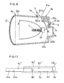
- the luminaire in another embodiment of the present invention as shown in FIG. 7 comprises the discharge lamp 1, socket 2a, reflector 3, lamp 5f, lighting unit 6f, elastic member 7a and coupler 8e.
- the lamp 5f is constituted by the lens 51 and the lamp body 52f made of a metal and housing therein the discharge lamp 1, socket 2a and reflector 3.
- This lamp body 52f is formed in a box shape having a front opening to be closed by the lens 51 and the opening 521f over a wide range covering both of downward rear side and rearward upper side with respect to the discharge lamp 1. Adjacent the opening 521f of the lamp body 52f, a plurality of the tapped holes for the screws S are formed.
- the lighting unit 6f is provided integrally with the lighting device 62a and block member 61f, while the block member 61f is formed with a metal plate having the shield effect into a shape blocking the opening 521f of the lamp body 52f or, in concrete, in an L-shape in section to be directed upward in one surface and forward in the other surface and having engaging stepped parts 611f at respective edges on the lower and rear sides.
- a plurality of through holes are bored for the screws S.
- the elastic member 7a is adhered to inner surface at edge portions of the respective fitting stepped parts 611f.
- a through hole 615f for connection between the lighting device 62a and the coupler 8e is made in a mounting wall for the lighting device 62a of the block member 61f, the coupler 8e is mounted to outer surface of the block member 61f at the position of the through hole 615f, and respective connecting terminals of the coupler 8e and the respective power source terminals of the lighting device 62a are electrically connected through the through hole 615f.
- the arrangement is so made that the lighting device 62a is mounted to inner surface on lower side of the block member 61f, and output lines are electrically connected through the cables W1 to the respective connecting terminals of the socket 2a.
- the lighting device 62a is disposed at a lower corner of the rear wall of the lamp body 52b to be in the horizontal direction.
- the luminaire in another embodiment of the present invention as shown in FIG. 8 comprises the discharge lamp 1, socket 2a, reflector 3, lamp 5e, lighting device 6e, elastic member 7a and coupler 8e, and a wiring harness H is connected to the coupler 8e.
- the lamp 5e is constituted by the lens 51 and the metal made lamp body 52e housing therein the discharge lamp 1, socket 2a and reflector 3.
- This lamp body 52e is formed in the box shape having the front opening which is closed by the lens 51, and is provided with the opening 521e in a wide range covering both of the upper rearward side and rear lower side with respect to the discharge lamp 1. Adjacent the opening 521e of the lamp body 52e, further, a plurality of the tapped holes for the screws S are formed.
- the lighting unit 6e is so constituted as to be provided integrally with the lighting device 62a and block member 61e.
- the block member 61e is formed, by the metal plate having the shield effect, in a shape blocking the opening 521e of the lamp body 52e or, in concrete, in an L-shape in section to face downward at one surface and forward at the other surface and having the fitting stepped parts 611e at respective edge parts on the upper and rear sides with respect to the discharge lamp 1.
- the respective fitting stepped parts 611e of the block member 61e are provided with the plurality of through holes (not shown) for the screws S. To the inner surface at edge portions of the respective fitting stepped parts 611e, further, the elastic member 7a is adhered.
- the mounting wall for the lighting device 62a is bored to have the through hole 615e for the connection between the lighting device 62a and the coupler 8e.
- the lighting device 62a is mounted to the inner surface of the rear side of the block member 61e, and is so constituted that its outputs are electrically connected through the cables W1 to the respective connection terminals of the socket 2a.
- the lighting device 62a is disposed to be vertical at upper corner of the rear wall in the lamp body 52e.
- the same safetyness as in the above described embodiment can be attained by providing the igniter to the socket. and disposing the inverter in the lighting device.
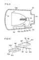
- the luminaire in another embodiment of the present invention as shown in FIG. 9 comprises the discharge lamp 1, socket 2a, reflector 3, lamp 5b, lighting unit and couplers 8a, 8b, 8b' and 8b". More specifically, the discharge lamp 1 such as the HID lamp is disposed in the lamp body 52b provided with the reflector 3 such as the concave mirror, and a housing chamber 5a' for housing the lighting device 62a is formed in interior space of the lamp body 52b.
- the lamp cover 4a is provided to the rear wall to cover the opening of the lamp body 52a.
- the lamp body 52a and lamp cover 4a are detachably coupled with such fixing tool as the screws employed.
- the lamp cover 4a is detached from the lamp body 52b at the time when the discharge lamp 1 is exchanged and so on.
- the front side of the lamp body 52b should preferably be covered by a lamp cover having the light transmitting properties.
- the housing chamber 5a' is a space enclosed by a partition 8a" formed to be U-shaped in section and integral with a planar part of the inner periphery of the lamp body 52b, as shown in FIG. 10, and the coupler 8b is provided to a surface of the housing chamber 5a' on the rear end side of the lamp body 52b.
- This coupler 8b may be integrally molded with the lamp body 52b.
- the socket 2a is connected through the load cables W1 forming the harness, and a power-source coupler 8a as a power source connector is connected through a power source cable W2 forming the harness.
- the socket 2a is fixed to the regular position on rear side surface of the reflector 3 in the interior of the lamp body 52b so as to hold the discharge lamp 1 and to electrically connect the load cable W1 to the discharge lamp 1.
- the power-source coupler 8a is fixed as passed through the rear wall, and connecting part of the power-source coupler 8a is formed on outer side of the lamp body 52a.
- the connecting part of the coupler 8b is formed on inner side of the housing chamber 5a', and the coupler 8b' provided to the lighting device 62a is detachably coupled to this coupler 8b.
- the lighting device 62a is constituted by housing in the block member 61a of a rectangular parallelepiped shape the igniter 62a' applying a high voltage pulse to the discharge lamp 1 upon its starting and the inverter 62a" maintaining the lighting of the discharge lamp 1 with the DC source power converted, and the coupler 8b' is mounted to one surface of the block member 61a.
- This coupler 8b' is provided with contacters electrically connected to the power source and to the discharge lamp 1.
- the lighting device 62a is to be mounted to the lamp body 52b as the block member 61a of the lighting device 62a is inserted from the opening side of the housing chamber 5a' up to a position where the coupler 8b' is coupled to the coupler 8b. Further, because the socket 2a and coupler 8b are connected by means of the load cable W1 and the source coupler 8a and coupler 8b are connected by means of the source cable W2, the electric connection and mechanical fixation are to be simultaneously attained as the lighting device 62a is mounted to the housing chamber 5a'.
- the housing chamber 5a' is provided on inner periphery adjacent to the opening thereof with a locking projection 5a" which increases its projection from the side of the opening toward inner side, so that the block member 61a of the lighting device 62a will be locked by the locking projection 5a" at the position where the coupler 8b of the lighting device 62a is coupled to the coupler 8b fixed to the lamp body 5a.
- the block member 61a of the lighting device 62a is to be so locked as to be in the state of being housed in the housing chamber 5a' and not to fall off from the housing chamber 5a'.
- the interposition of the reflector 3 and lamp cover 4a between the device and the discharge lamp 1 enables to restrain any overheat of the lighting device 62a.
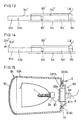
- FIGS. 12 through 14 As regards the constitution for fixing the block member 61a of the lighting device 62a to the housing chamber 5a' without the falling off, such constitution as shown in FIGS. 12 through 14 may be adopted. That is, as shown in FIG. 12, a locking recess 5a"' is provided in a surface of the block member 61a opposing to the partition 8b", and the locking projection 5a" which engages in the locking recess 5a"' in the state where the block member 61a is mounted to the housing chamber 5a' is provided to project on the inner periphery of the partition 8b". Further, as shown in FIG.
- the locking projection 5a"' is provided to project on the surface of the block member 61a opposing to the partition 8b"' while the locking recess 58"' is provided to the partition 8b" so that the same function as that shown in FIG. 12 will be attained.
- the block member 61a is provided with a mounting leaf 61a' projecting at an end part opposite to the coupler 8b', and a fixing screw 61a" passed through the mounting leaf 61a' is screwed to part of the partition 8b".
- the block member 61a is to be fixed to the lamp body 5a by means of the fixing screw 61a", and it is possible to further increase the coupling strength of the lighting device 62a with respect to the lamp body 5a.
- the luminaire in another embodiment of the present invention shown in FIG. 15 comprises the discharge lamp 1, socket 2a, reflector 3, lamp 5h, lighting unit 6h, elastic member 7h and coupler 8e.
- the lamp 5h is constituted by the lens 51 and the metal-made lamp body 52h housing therein the discharge lamp 1, socket 2a and reflector 3.
- This lamp body 52h is formed in a box shape having a front opening closed by the lens 51 and a circular opening 521h on the rear side with respect to the discharge lamp 1.
- a plurality of tapped holes for the screws S are formed adjacent to the opening 521h of the lamp body 52h.
- the lighting unit 6h is provided integrally with the lighting device 62a and block member 61h.
- This block member 61h is formed with the metal plate or the like having the shield effect, into a shape blocking the opening 521h of the lamp body 52h or, in concrete, into a bottomed cylinder having the front opening and a flange 616h provided along peripheral edge of the opening.
- a plurality of projected leaves 614h having through holes 613h for the screws S are sequentially provided as mutually separated on outer periphery of the flange 616h.
- a through hole (not shown) is provided as projected for connection of the lighting device 62a and coupler 8e, the coupler 8e can be mounted to outer surface of the block member 61h having this through hole, and the respective connecting terminals of the coupler 8e are to be electrically connected to the source terminals of the lighting device 62a through the through hole.
- connection between the lighting device including the inverter and the socket provided with the igniter may be replaced by a connection of the harness and coupler or a connection only by means of the coupler.
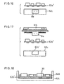
- the coupler 8e may be secured to a casing 62c on which the inverter 62a" is loaded, and if required the coupler 8e can be made to be in a waterproof type.
- the constitution may be such that the casing 62c carrying the inverter 62a" may be provided with a fitting notch 62c', the coupler 8e is secured to the block member 61h and, when the inverter 62a" is coupled to the block member 61h, the coupler 8e will be fitted in the fitting notch 62c'.
- FIG. 18 further, such electronic parts 30 as the inverter 62a and so on are housed in the casing 62c, and a resin 62d is pored in the interior of this casing 62c. This attains an attempt of heat radiation from the electronic parts and discharge lamp when the casing 62c is made of a metal.
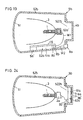
- the constitution may be such that a discharge lamp 1 connected to the cable W1 without the socket 2a is used, and the discharge lamp 1 incorporates therein the igniter 62a'.
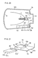
- the lighting device 62a in other embodiments of the present invention is provided with two couplers 8b', one of which couplers 8b' is coupled to a coupler 27 disposed between the peripheral wall of the lamp body 52b and the housing chamber 5a', and this coupler 27 is connected through the cable W1 comprising the harness to the socket 2a.
- a gap corresponding to the coupler 27 is formed, and a projection 61a"' of dimensions corresponding to this gap is formed in the case 61a of the lighting device 62a.
- the other coupler 8b' is formed in a shape projecting out of the projection 61a"'.
- the couplers 8b' are formed by a conducting pattern at end parts of a printed wiring substrate on which circuit parts constituting the lighting device 62a are mounted. That is, the printed wiring substrate is partly projected, and the coupler 8b' is formed on this projected part by forming a plurality of linear conducting patterns along projecting direction.
- the coupler 8b' is connectable to a card edge connector, and forms a power source connecting section connected to the power source.
- a through hole 8b"' for passing the projection 61a" is formed, and a lead hole 10c for passing the coupler 8b' is formed in the peripheral wall of the lamp body 5a.
- an elastic member 28 acting as a packing is disposed so that, in the state where the case 61a is mounted to the housing chamber 5a', the elastic member 28 will be held between the projection 61a" and the inner surface of the peripheral wall of the lamp body 5a. By holding in this way the elastic member 28 between the case 61a and the lamp body 5a, the waterproofness around the lead hole 10c can be assured. Also in this state, the coupler 8b' is coupled to the coupler 27.
- the socket 2a is connected through the cable W1 to the coupler 27 housed in the interior of the lamp body 5a, so that, similar to the first embodiment, the lighting device 62a and socket 2a can be connected just by mounting the lighting device 62a to the housing chamber 5a', and the assembling work is rendered easier.
- the coupler 8b' for connected to the power source through the lead hole 10c formed in the peripheral wall of the lamp body 5a is projected out of the lamp body 5a, so that, as compared with the foregoing embodiments, the cable W1 is made unnecessary and the assembling work is made more easier.
- Other constitution and operation are the same as in the foregoing embodiments.
- the housing chamber 522a to which the parallelepiped case 61a of the lighting device 62a is mountable is provided on the lamp cover 4b. That is, a space communicating with the inner side of the lamp body 5a in the lamp cover 4b is provided as recessed, and the housing chamber 522b is formed at such recessed portion.
- the load side coupler 8b' is provided, while on opposing side to the inner periphery of the lamp cover 4b the source coupler 8a to which the coupler 8b' can be coupled is mounted.
- the coupler 8b' is connected to the socket 2a employing the cable W1 forming the harness.
- the lighting device 62a is made detachable only by dismounting the lamp cover 4b from the lamp body 52b, and the assembling work is rendered easier. Since the lighting device 62a is housed in the lamp cover 4b, further, no waterproofing is required therefor, so as to result in the reduction of costs.
- the luminaire in another embodiment according to the present invention as shown in FIGS. 25 and 26 comprises the discharge lamp 1, socket 2a, reflector 3, elastic member 7h and coupler 8e, as well as the lamp body 5j and lighting unit 6j.
- the lamp body 5j is constituted by the lens 51 and the metal made lamp body 52j housing therein the discharge lamp 1, socket 2a and reflector 3.
- This lamp body 52j is formed into the box shape having the front opening closed by the lens 51 and the circular opening 521j on rear side of the discharge lamp 1.
- the opening 521j is provided with sequential grooves (not shown) for inserting bent projections 617j later described.
- the lighting unit 6j is so constituted as to be integrally provided with the lighting device 52a and block member 61j.
- This block member 61j is formed with a metal plate or the like having the shield effect, in a shape for blocking the opening 521j of the lamp body 52j or, in concrete, a box shape having a front opening (a bottomed box shape in FIGS. 25 and 26) and a flange 616j on the peripheral edge of the opening.
- the block member 61j is formed to have a plurality of the bent projections 617j in a state mutually separated as extended forward from base part of the flange 616j and bent outward. Onto front face of the flange 616j, the elastic member 7h is adhered.
- a through hole (not shown) for the connection between the lighting device 62a and the coupler 8e is bored, the coupler 8e is mounted to the outer surface of the block member 61j having the through hole, and the respective connecting terminals of the coupler 8e are electrically connected to the source terminals of the lighting device 62a.
- the discharge lamp 1 is mounted to the rearmost part of the reflector 3 as inserted through the hole of the reflector 3 into the concave mirror, and then the socket 2a is mounted to the electrode section of the discharge lamp 1.
- the lighting unit 6j is fitted as rotated into the opening 521j of the lamp body 52j with the lighting device 62a side disposed frontward. Whereby the interior of the lamp 5j is made in a sealed state.
- the block member 61j of the lighting unit 6j also acts as the lamp cover, the reduction of the parts number is made possible. Further, as the block member 61j of the lighting unit 6j is disposed rearward, the exchange work of the discharge lamp 1 is made easier. Yet, as the coupler 8e is connected through the through hole in the block member 61j to the lighting device 62a, it is possible to attain the optimum waterproof with respect to the interior of the lamp body 5j by adopting additionally the waterproof structure only with respect to the part of the through hole.
Landscapes
- Engineering & Computer Science (AREA)
- General Engineering & Computer Science (AREA)
- Power Engineering (AREA)
- Mechanical Engineering (AREA)
- Non-Portable Lighting Devices Or Systems Thereof (AREA)
- Arrangement Of Elements, Cooling, Sealing, Or The Like Of Lighting Devices (AREA)
- Circuit Arrangements For Discharge Lamps (AREA)
- Fastening Of Light Sources Or Lamp Holders (AREA)
Abstract
An illumination device comprises a discharge lamp, a lighting device
for supplying electric power to the discharge lamp, and a body housing the
discharge lamp and the igniter for starting the discharge lamp. The lighting device
and the igniter are separated, and the lighting device is housed in the body. The
length of high-voltage parts, such as harness, for use with the lighting device is reduced
to assure safety.
Description
This invention relates to luminaires, for example, a
luminaire employed in automotive head lamp.
The luminaires employed in the automotive head lamps have
been disclosed in Japanese Patent Laid-Open Publications Nos.
7-57503 and 10-147174, Japanese Patent No. 2,761,132, U.S. Patent
No. 6,066,921 and so on. In particular, U.S. Patent No. 6,066,921
has been assigned to the same assignee as the assignee of the present
application, and its luminaire comprises a lamp including a
discharge lamp, socket, reflector, lamp cover, lens and lamp body,
a lighting device including an inverter and igniter, and a coupler,
wherein the socket connected through cables to the lighting device
is inserted in the lamp.
In the conventional luminaire as in the above, however, there
have been problems that, since in general the socket and igniter
in the lighting device are connected through a harness, parts of
a high withstand-voltage are required when a high voltage is applied
to the harness, the startability is deteriorated, and so on.
The present invention is to overcome the foregoing problems,
and its object is to provide a luminaire which can reduce the length
of such part to which the high voltage is applied as the harness
employed in the lighting circuit, and which can attain an excellent
startability.
In order to solve the above problems, it is an object that
the luminaire according to the present invention is characterized
in comprising a discharge lamp, a lighting device for supplying a
power for lighting the discharge lamp, an igniter for starting the
discharge lamp, and a lamp body having at least a discharge-lamp
holding member and housing the discharge lamp, wherein the lighting
device and igniter are provided as separated, the lighting device
is provided in the lamp body, and the igniter is provided adjacent
to the discharge lamp.
Other objects and advantages of the present invention should
become clear from the description made in the followings with
reference to embodiments shown in accompanying drawings.
While the present invention shall now be described with
reference to the respective embodiments shown in the accompanying
drawings, it should be appreciated that the intention is not to limit
the present invention only to these embodiments but rather to
include all alterations, modifications and equivalent arrangements
possible within the scope of appended claims.
The luminaire in an embodiment of the present invention as
shown in FIGS. 1-3 may be used as an automotive head lamp, which
comprises, in concrete, such discharge lamp 1 as a metal halide lamp,
a socket 2a formed in a bottomed cylindrical shape capable of
mounting a rear (righthand in the drawings) electrode section of
the discharge lamp 1 and having connecting terminals for electrical
connection to respective electrodes of the discharge lamp 1 and,
preferably, an igniter 62a' incorporated, a reflector 3 which is
a concave mirror (mirror of paraboloid of revolution in the
drawings) for reflecting luminous light of the discharge lamp 1
forward (leftward in the drawing) and having a hole at the rearmost
part for inserting the discharge lamp 1 into the concave mirror,
and a lamp cover 4b for mounting and exchanging the discharge lamp
1 and formed in a box shape opened on front face (including a bottomed
cylinder) . Further, a lamp 5b, a lighting unit 6b, an elastic member
7b and a coupler 8b are provided. Further, similar to conventional
one, the reflector 3 is mounted inside the lamp 5b to be adjustable
in the angle. The lighting unit 6b has a lighting device 62a
including an inverter 62a", and the inverter 62a" is to be installed
as separated from the igniter 62a' mounted to the socket 2a.
The lamp 5b is constituted by a lens 51 consisting of such
light transmitting material as glass and disposed in front of the
discharge lamp 1, and a metal-made lamp body 52b for housing in the
interior the discharge lamp 1, socket 2a and reflector 3. This lamp
body 52b is formed in a box shape having a front opening closed by
the lens 51, an opening 521b made in a range (part) covering both
of upper rear side and rear upper side with respect to the discharge
lamp 1, and another opening 522b on rear center side. Adjacent the
opening 521b of the lamp body 52b, tapped holes are provided for
use with screws S. Further, to the opening 522b of the lamp body
52b, respective projections 41b of the lamp cover 4b are engaged.
The lighting unit 6b is constituted to be integrally provided
with a block member 61b and the lighting device 62a. The block
member 61b is made by a metal plate or the like having a shield effect,
and to have a shape which blocks the opening 521b of the lamp body
52b or, in concrete, to have fitting parts 611b with respect to the
opening 521b at respective edge parts on upper and rear sides with
respect to the discharge lamp 1, so as to be L-shaped in section
and facing at one surface downward and at the other surface forward.
Further, the respective fitting parts 611b have a plurality of
through holes 613b for passing the screws S. On the other hand,
the lighting device 62a is to start and light the discharge lamp,
and is mounted to inner surface of the block member 61b. Also, to
the lighting device 62a, the socket 2a is connected through, for
example, two cables W1 used as the harness, and outputs of the
lighting device 62a and respective connecting terminals of the
socket 2a are electrically connected. Further, the lighting device
62a is provided with, for example, a coupler exposed to the exterior,
as a constitution for the supply of power from the exterior.
The elastic member 7 comprises a rubber member or the like
which is interposed between the lamp 5b and the block member 61b
for sealing between them. Further, the elastic member 7b is adhered
to, for example, inner surface of edge parts of the respective
fitting parts 611b or to projections 612b of the lighting unit 6b,
by means of an adhesive, double-side adhesive tape or the like.
Referring next to an example of assembling sequence of the
lighting unit 6b to the lamp 5b, the lighting unit 6b with the side
of the lighting device 62a faced down is first fitted into the opening
521b of the lamp body 52b, and next the lighting unit 6b is screwed
to the lamp body 52b using the plurality of screws S. Next, the
discharge lamp 1 is inserted through the hole of the reflector 3
into the concave mirror and is mounted to the rearmost part of the
reflector 3. In this case, the arrangement may be so made as to
mount the discharge lamp 1 to the rearmost part of the reflector
3 through a mounting member (such as a fixture or the like), or to
constitute the reflector 3 for allowing the discharge lamp 1 to be
directly mounted to the rearmost part. The socket 2a provided with
the igniter 62a' is mounted to the electrode part of the discharge
lamp 1, and then the lamp cover 4b is fitted as rotated to the lamp
body 522b. Whereby the interior of the lamp 5b can be made to be
in a sealed state.
It is needless to say that the assembly sequence is not limited
to the above but other assembly sequence may be adopted. For example,
the assembly sequence may be such that the lighting unit 6b is first
fitted in the opening 521b of the lamp body 52b, then the lighting
unit 6b is screwed to the lamp body 52b with the plurality of screws
S, thereafter the electrode part of the discharge lamp 1 is mounted
to the socket 2a, subsequently the discharge lamp 1 is inserted into
the concave mirror through the hole of the reflector 3, and the
discharge lamp 1 and socket 2a are mounted to the rearmost part of
the reflector 3. Thereafter, the lamp cover 4b is fitted as rotated
into the opening 521b of the lamp body 52b. In this case, the
arrangement may also be such that the discharge lamp 1 and socket
2a integrally mounted with a mounting fixture or the like employed
is mounted to the rearmost part of the reflector 3, or the reflector
3 may be so constituted as to allow the discharge lamp 1 and socket
2a to be directly mounted to the rearmost part.
Now, since in the present embodiment the igniter 62a' and
inverter 62a" are mutually separated but connected inside the lamp
body 52b with the cables W1 used as the harness which is not exposed
to the exterior, the safety can be improved.
Further, it is possible to render the interior of both of
the lighting device 62a and lamp 5b to be waterproof without
requiring either a waterproof structure in double or a cover of
exclusive use for the waterproofness, by constituting the lighting
unit 6b with the block member 61b formed in the shape for blocking
the opening 521b of the lamp 5b and with the lighting device 62a
mounted to the inner surface of this block member 61b, and employing
the elastic member 7b interposed between the lamp 5b and the block
member 61b for sealing between them. This allows the parts to be
reduced and the waterproof mechanism to be simplified. Further,
as the lighting device 62a is not required to be of the waterproof
structure, it is possible to reduce the total costs.
Further, the lamp body 52b and block member 61b may of course
not be limited to be of a metal but may be of a plated one on a resin
to have shielding effect. Further, the elastic member 7b of a
structure capable of being adhered to the inner surface of edge parts
of the respective fitting parts 611b of the lighting unit 6b may
also be employed.
The luminaire in another embodiment of the present invention
as shown in FIGS. 4 and 5 comprises the discharge lamp 1, socket
2a, reflector 3, lamp 5h, lighting unit 6i and elastic member 7h.
The block member 61i provided integrally with the lighting unit 6i
is formed with a metal plate or the like having the shielding effect
into a shape capable of blocking the opening 521h of the lamp body
52h or, in concrete, a bottomed cylindrical shape opened on front
side, and having in the middle of side face a flange 616i provided
peripherally. Further, the flange 616i has on its outer periphery
a plurality of projections 614i sequentially provided in a state
mutually separated and made to have through holes 613i for the screws
S. Further on the front face of the flange 616i, the elastic member
7h is adhered. In a mounting wall of the block member 61i for the
lighting device 62a, a through hole (not shown) is bored for
connection between the lighting device 62a and a coupler 8e which
is mounted to outer face of the block member 61i where the through
hole is present, and respective connecting terminals of the coupler
8e are electrically connected to power source terminals of the
lighting device 62a.
Referring next to an example of the assembly sequence of the
lighting unit 6i to the lamp 5h, initially the discharge lamp 1 is
inserted through the hole of the reflector 3 into the concave mirror
and mounted to the rearmost part of the reflector 3, and then the
socket 2a is mounted to the electrode part of the discharge lamp
1, thereafter the aperture 521h of the lamp body 52h is blocked by
the lighting unit 6i with its side of the lighting device 62a faced
frontward, and subsequently the lighting unit 6i is fastened to the
lamp body 52h by means of the plurality of screws S. The interior
of the lamp 5h is thereby made in the sealed state.
As has been described, both of the lighting device 62a and
the interior of the lamp 5h can be made waterproof without requiring
either the waterproof structure in double or the cover of exclusive
use for the waterproofness, by constituting the light unit 6i with
the block member 61i formed in a shape capable of blocking the
aperture 521h of the lamp 5h as well as the lighting device 62a
mounted to the inner wall of the block member 61i, and employing
the elastic member 7h interposed between the lamp 5h and the block
member 61i for sealing between them. As a result, the reduction
of parts and simplification of the waterproof mechanism can be made
possible. It is also not required to provide the lighting device
62a in the waterproof structure, and the total cost reduction is
possible.
Further, as the block member 61i of the lighting unit 6i acts
also as the lamp cover, the reduction of parts number is possible.
As the block member 61i of the lighting unit 6i is disposed rearward,
further, a work for exchanging the discharge lamp 1 is easier. As
the coupler 8e is connected to the lighting device 62a through the
through hole of the block member 61i, further, the interior of the
lamp 5h can be made more optimumly waterproof only by employing a
further waterproof structure only with respect to the portion of
the through hole.
According to the present invention, further, the lighting
unit can be disposed at appropriate position. In the luminaire of
another embodiment of the present invention as shown in FIG. 6, the
lamp cover 4a is for mounting and exchanging the discharge lamp 1
and is formed in a box shape having a front opening and a flange
41a formed outward at edge part of the front opening. This lamp
cover 4a is mounted to the lamp 5a by means of, for example, screws
(not shown) or the like.
The lamp 5a is constituted by the lens 51, and the lamp body
52a made of a metal and housing therein the discharge lamp 1, socket
2a and reflector 3. The lamp body 52a is formed in a box shape having
the front opening which is blocked by the lens 51, as well as an
opening 521a on lower side with respect to the discharge lamp 1 and
another opening 522a on rearward center side to be blocked by the
lamp cover 4a. Further, adjacent the opening 521a of the lamp body
52a, a plurality of tapped holes for the screws S are formed. The
lighting unit 6a is so constituted as to integrally provided with
the lighting device 62a and block member 61a, and the lighting device
62a is formed in a box shape opened upward while having a fitting
part 611a to be fitted in the opening 521a and being one size larger
than the fitting part 611a.
In this case, the fitting part 611a of the lighting unit 6a
is first fitted in the opening 521a of the lamp body 52a with the
lighting device 62a disposed downward, and then the lighting unit
6a is fastened to the lamp body 52a by means of the screws S. At
this time, the elastic member 7a is disposed between edge parts of
the opening 521a and of the fitting part 611a. Thereby the lighting
unit 6a, in particular, the lighting device 62a is disposed at upper
corner part of rear wall in the lamp body 52a as aligned with
horizontal direction.
The luminaire in another embodiment of the present invention
as shown in FIG. 7 comprises the discharge lamp 1, socket 2a,
reflector 3, lamp 5f, lighting unit 6f, elastic member 7a and coupler
8e. The lamp 5f is constituted by the lens 51 and the lamp body
52f made of a metal and housing therein the discharge lamp 1, socket
2a and reflector 3. This lamp body 52f is formed in a box shape
having a front opening to be closed by the lens 51 and the opening
521f over a wide range covering both of downward rear side and
rearward upper side with respect to the discharge lamp 1. Adjacent
the opening 521f of the lamp body 52f, a plurality of the tapped
holes for the screws S are formed.
The lighting unit 6f is provided integrally with the lighting
device 62a and block member 61f, while the block member 61f is formed
with a metal plate having the shield effect into a shape blocking
the opening 521f of the lamp body 52f or, in concrete, in an L-shape
in section to be directed upward in one surface and forward
in the other surface and having engaging stepped parts 611f at
respective edges on the lower and rear sides. In the respective
engaging stepped parts 611f of the block member 61f, further, a
plurality of through holes (not shown) are bored for the screws S.
Further, the elastic member 7a is adhered to inner surface at edge
portions of the respective fitting stepped parts 611f. A through
hole 615f for connection between the lighting device 62a and the
coupler 8e is made in a mounting wall for the lighting device 62a
of the block member 61f, the coupler 8e is mounted to outer surface
of the block member 61f at the position of the through hole 615f,
and respective connecting terminals of the coupler 8e and the
respective power source terminals of the lighting device 62a are
electrically connected through the through hole 615f.
In this case, the arrangement is so made that the lighting
device 62a is mounted to inner surface on lower side of the block
member 61f, and output lines are electrically connected through the
cables W1 to the respective connecting terminals of the socket 2a.
In this embodiment of FIG. 7, the lighting device 62a is disposed
at a lower corner of the rear wall of the lamp body 52b to be in
the horizontal direction.
The luminaire in another embodiment of the present invention
as shown in FIG. 8 comprises the discharge lamp 1, socket 2a,
reflector 3, lamp 5e, lighting device 6e, elastic member 7a and
coupler 8e, and a wiring harness H is connected to the coupler 8e.
The lamp 5e is constituted by the lens 51 and the metal made
lamp body 52e housing therein the discharge lamp 1, socket 2a and
reflector 3. This lamp body 52e is formed in the box shape having
the front opening which is closed by the lens 51, and is provided
with the opening 521e in a wide range covering both of the upper
rearward side and rear lower side with respect to the discharge lamp
1. Adjacent the opening 521e of the lamp body 52e, further, a
plurality of the tapped holes for the screws S are formed.
The lighting unit 6e is so constituted as to be provided
integrally with the lighting device 62a and block member 61e. The
block member 61e is formed, by the metal plate having the shield
effect, in a shape blocking the opening 521e of the lamp body 52e
or, in concrete, in an L-shape in section to face downward at one
surface and forward at the other surface and having the fitting
stepped parts 611e at respective edge parts on the upper and rear
sides with respect to the discharge lamp 1. The respective fitting
stepped parts 611e of the block member 61e are provided with the
plurality of through holes (not shown) for the screws S. To the
inner surface at edge portions of the respective fitting stepped
parts 611e, further, the elastic member 7a is adhered. In the block
member 61e, the mounting wall for the lighting device 62a is bored
to have the through hole 615e for the connection between the lighting
device 62a and the coupler 8e.
However, the lighting device 62a is mounted to the inner
surface of the rear side of the block member 61e, and is so
constituted that its outputs are electrically connected through the
cables W1 to the respective connection terminals of the socket 2a.
In the present embodiment of FIG. 8, the lighting device 62a is
disposed to be vertical at upper corner of the rear wall in the lamp
body 52e.
Also in the respective embodiments shown in FIGS. 4 and 5
and in each of FIGS. 6-8, the same safetyness as in the above
described embodiment can be attained by providing the igniter to
the socket. and disposing the inverter in the lighting device.
The luminaire in another embodiment of the present invention
as shown in FIG. 9 comprises the discharge lamp 1, socket 2a,
reflector 3, lamp 5b, lighting unit and couplers 8a, 8b, 8b' and
8b". More specifically, the discharge lamp 1 such as the HID lamp
is disposed in the lamp body 52b provided with the reflector 3 such
as the concave mirror, and a housing chamber 5a' for housing the
lighting device 62a is formed in interior space of the lamp body
52b. The lamp cover 4a is provided to the rear wall to cover the
opening of the lamp body 52a. The lamp body 52a and lamp cover 4a
are detachably coupled with such fixing tool as the screws employed.
The lamp cover 4a is detached from the lamp body 52b at the time
when the discharge lamp 1 is exchanged and so on. The front side
of the lamp body 52b should preferably be covered by a lamp cover
having the light transmitting properties.
The housing chamber 5a' is a space enclosed by a partition
8a" formed to be U-shaped in section and integral with a planar part
of the inner periphery of the lamp body 52b, as shown in FIG. 10,
and the coupler 8b is provided to a surface of the housing chamber
5a' on the rear end side of the lamp body 52b. This coupler 8b may
be integrally molded with the lamp body 52b. To the coupler 8b,
further, the socket 2a is connected through the load cables W1
forming the harness, and a power-source coupler 8a as a power source
connector is connected through a power source cable W2 forming the
harness. The socket 2a is fixed to the regular position on rear
side surface of the reflector 3 in the interior of the lamp body
52b so as to hold the discharge lamp 1 and to electrically connect
the load cable W1 to the discharge lamp 1. On the other hand, the
power-source coupler 8a is fixed as passed through the rear wall,
and connecting part of the power-source coupler 8a is formed on outer
side of the lamp body 52a.
The connecting part of the coupler 8b is formed on inner side
of the housing chamber 5a', and the coupler 8b' provided to the
lighting device 62a is detachably coupled to this coupler 8b. The
lighting device 62a is constituted by housing in the block member
61a of a rectangular parallelepiped shape the igniter 62a' applying
a high voltage pulse to the discharge lamp 1 upon its starting and
the inverter 62a" maintaining the lighting of the discharge lamp
1 with the DC source power converted, and the coupler 8b' is mounted
to one surface of the block member 61a. This coupler 8b' is provided
with contacters electrically connected to the power source and to
the discharge lamp 1. For the coupler 8b', one which is mechanically
coupled at a relatively high strength to the coupler 8b is employed.
Therefore, the lighting device 62a is to be mounted to the lamp body
52b as the block member 61a of the lighting device 62a is inserted
from the opening side of the housing chamber 5a' up to a position
where the coupler 8b' is coupled to the coupler 8b. Further, because
the socket 2a and coupler 8b are connected by means of the load cable
W1 and the source coupler 8a and coupler 8b are connected by means
of the source cable W2, the electric connection and mechanical
fixation are to be simultaneously attained as the lighting device
62a is mounted to the housing chamber 5a'.
In this case, as shown in FIG. 11, the housing chamber 5a'
is provided on inner periphery adjacent to the opening thereof with
a locking projection 5a" which increases its projection from the
side of the opening toward inner side, so that the block member 61a
of the lighting device 62a will be locked by the locking projection
5a" at the position where the coupler 8b of the lighting device 62a
is coupled to the coupler 8b fixed to the lamp body 5a. With this
arrangement, the block member 61a of the lighting device 62a is to
be so locked as to be in the state of being housed in the housing
chamber 5a' and not to fall off from the housing chamber 5a'.
Consequently, there is no member which penetrates throughout the
lamp body 5a except for the source coupler 8a, and no waterproofing
is required for the lighting device 62a, so as to result in the
reduction of costs. Further, while the lighting device 62a is
housed within the lamp body 5a, the interposition of the reflector
3 and lamp cover 4a between the device and the discharge lamp 1
enables to restrain any overheat of the lighting device 62a.
As regards the constitution for fixing the block member 61a
of the lighting device 62a to the housing chamber 5a' without the
falling off, such constitution as shown in FIGS. 12 through 14 may
be adopted. That is, as shown in FIG. 12, a locking recess 5a"'
is provided in a surface of the block member 61a opposing to the
partition 8b", and the locking projection 5a" which engages in the
locking recess 5a"' in the state where the block member 61a is mounted
to the housing chamber 5a' is provided to project on the inner
periphery of the partition 8b". Further, as shown in FIG. 13, the
locking projection 5a"' is provided to project on the surface of
the block member 61a opposing to the partition 8b"' while the locking
recess 58"' is provided to the partition 8b" so that the same function
as that shown in FIG. 12 will be attained. As shown in FIG. 14,
further, the block member 61a is provided with a mounting leaf 61a'
projecting at an end part opposite to the coupler 8b', and a fixing
screw 61a" passed through the mounting leaf 61a' is screwed to part
of the partition 8b". With this constitution, therefore, the block
member 61a is to be fixed to the lamp body 5a by means of the fixing
screw 61a", and it is possible to further increase the coupling
strength of the lighting device 62a with respect to the lamp body
5a.
The luminaire in another embodiment of the present invention
shown in FIG. 15 comprises the discharge lamp 1, socket 2a, reflector
3, lamp 5h, lighting unit 6h, elastic member 7h and coupler 8e. The
lamp 5h is constituted by the lens 51 and the metal-made lamp body
52h housing therein the discharge lamp 1, socket 2a and reflector
3. This lamp body 52h is formed in a box shape having a front opening
closed by the lens 51 and a circular opening 521h on the rear side
with respect to the discharge lamp 1. A plurality of tapped holes
for the screws S are formed adjacent to the opening 521h of the lamp
body 52h.
The lighting unit 6h is provided integrally with the lighting
device 62a and block member 61h. This block member 61h is formed
with the metal plate or the like having the shield effect, into a
shape blocking the opening 521h of the lamp body 52h or, in concrete,
into a bottomed cylinder having the front opening and a flange 616h
provided along peripheral edge of the opening. A plurality of
projected leaves 614h having through holes 613h for the screws S
are sequentially provided as mutually separated on outer periphery
of the flange 616h. Further, on the mounting surface of the block
member 61h for the lighting device 62a, a through hole (not shown)
is provided as projected for connection of the lighting device 62a
and coupler 8e, the coupler 8e can be mounted to outer surface of
the block member 61h having this through hole, and the respective
connecting terminals of the coupler 8e are to be electrically
connected to the source terminals of the lighting device 62a through
the through hole.
In the present invention, further, various design
modification is possible. In particular, in the embodiment of FIGS.
1-3, the connection between the lighting device including the
inverter and the socket provided with the igniter may be replaced
by a connection of the harness and coupler or a connection only by
means of the coupler. As shown in FIG. 16, further, the coupler
8e may be secured to a casing 62c on which the inverter 62a" is loaded,
and if required the coupler 8e can be made to be in a waterproof
type. On the other hand, as shown in FIG. 17, the constitution may
be such that the casing 62c carrying the inverter 62a" may be provided
with a fitting notch 62c', the coupler 8e is secured to the block
member 61h and, when the inverter 62a" is coupled to the block member
61h, the coupler 8e will be fitted in the fitting notch 62c'. As
shown in FIG. 18, further, such electronic parts 30 as the inverter
62a and so on are housed in the casing 62c, and a resin 62d is pored
in the interior of this casing 62c. This attains an attempt of heat
radiation from the electronic parts and discharge lamp when the
casing 62c is made of a metal.
Also as shown in FIG. 19, the constitution may be such that
a discharge lamp 1 connected to the cable W1 without the socket 2a
is used, and the discharge lamp 1 incorporates therein the igniter
62a'.
In the present embodiment, as shown in FIGS. 20 and 21 and
in FIGS. 22 and 23, the lighting device 62a in other embodiments
of the present invention is provided with two couplers 8b', one of
which couplers 8b' is coupled to a coupler 27 disposed between the
peripheral wall of the lamp body 52b and the housing chamber 5a',
and this coupler 27 is connected through the cable W1 comprising
the harness to the socket 2a. Between the peripheral wall of the
lamp body 52b, a gap corresponding to the coupler 27 is formed, and
a projection 61a"' of dimensions corresponding to this gap is formed
in the case 61a of the lighting device 62a. The other coupler 8b'
is formed in a shape projecting out of the projection 61a"'. Here,
the couplers 8b' are formed by a conducting pattern at end parts
of a printed wiring substrate on which circuit parts constituting
the lighting device 62a are mounted. That is, the printed wiring
substrate is partly projected, and the coupler 8b' is formed on this
projected part by forming a plurality of linear conducting patterns
along projecting direction. The coupler 8b' is connectable to a
card edge connector, and forms a power source connecting section
connected to the power source. By such separate provision of the
load side and power source side couplers 8b', it is enabled to
separate between the interior wiring of the lamp body 5b and the
source power system from the exterior of the lamp body 5b, and any
leakage of load side output to the source side can be prevented.
In the partition 16 of the housing chamber 5a', a through hole 8b"'
for passing the projection 61a" is formed, and a lead hole 10c for
passing the coupler 8b' is formed in the peripheral wall of the lamp
body 5a. Around the lead hole 10c, an elastic member 28 acting as
a packing is disposed so that, in the state where the case 61a is
mounted to the housing chamber 5a', the elastic member 28 will be
held between the projection 61a" and the inner surface of the
peripheral wall of the lamp body 5a. By holding in this way the
elastic member 28 between the case 61a and the lamp body 5a, the
waterproofness around the lead hole 10c can be assured. Also in
this state, the coupler 8b' is coupled to the coupler 27.
In the constitution of the present embodiment, the socket
2a is connected through the cable W1 to the coupler 27 housed in
the interior of the lamp body 5a, so that, similar to the first
embodiment, the lighting device 62a and socket 2a can be connected
just by mounting the lighting device 62a to the housing chamber 5a',
and the assembling work is rendered easier. Yet, in the present
embodiment, the coupler 8b' for connected to the power source
through the lead hole 10c formed in the peripheral wall of the lamp
body 5a is projected out of the lamp body 5a, so that, as compared
with the foregoing embodiments, the cable W1 is made unnecessary
and the assembling work is made more easier. Other constitution
and operation are the same as in the foregoing embodiments.
In another embodiment according to the present invention
shown in FIG. 24, the housing chamber 522a to which the
parallelepiped case 61a of the lighting device 62a is mountable is
provided on the lamp cover 4b. That is, a space communicating with
the inner side of the lamp body 5a in the lamp cover 4b is provided
as recessed, and the housing chamber 522b is formed at such recessed
portion. On one surface of the case 61a which will be on the side
of the socket 2a in the state where the case 61a is mounted to the
housing chamber 522b, the load side coupler 8b' is provided, while
on opposing side to the inner periphery of the lamp cover 4b the
source coupler 8a to which the coupler 8b' can be coupled is mounted.
The coupler 8b' is connected to the socket 2a employing the cable
W1 forming the harness.
With the above constitution, the lighting device 62a is made
detachable only by dismounting the lamp cover 4b from the lamp body
52b, and the assembling work is rendered easier. Since the lighting
device 62a is housed in the lamp cover 4b, further, no waterproofing
is required therefor, so as to result in the reduction of costs.
The luminaire in another embodiment according to the present
invention as shown in FIGS. 25 and 26 comprises the discharge lamp
1, socket 2a, reflector 3, elastic member 7h and coupler 8e, as well
as the lamp body 5j and lighting unit 6j. The lamp body 5j is
constituted by the lens 51 and the metal made lamp body 52j housing
therein the discharge lamp 1, socket 2a and reflector 3. This lamp
body 52j is formed into the box shape having the front opening closed
by the lens 51 and the circular opening 521j on rear side of the
discharge lamp 1. The opening 521j is provided with sequential
grooves (not shown) for inserting bent projections 617j later
described.
The lighting unit 6j is so constituted as to be integrally
provided with the lighting device 52a and block member 61j. This
block member 61j is formed with a metal plate or the like having
the shield effect, in a shape for blocking the opening 521j of the
lamp body 52j or, in concrete, a box shape having a front opening
(a bottomed box shape in FIGS. 25 and 26) and a flange 616j on the
peripheral edge of the opening. Further, the block member 61j is
formed to have a plurality of the bent projections 617j in a state
mutually separated as extended forward from base part of the flange
616j and bent outward. Onto front face of the flange 616j, the
elastic member 7h is adhered. In mounting surface of the block
member 61j for the lighting device 62a, a through hole (not shown)
for the connection between the lighting device 62a and the coupler
8e is bored, the coupler 8e is mounted to the outer surface of the
block member 61j having the through hole, and the respective
connecting terminals of the coupler 8e are electrically connected
to the source terminals of the lighting device 62a.
Next, an example of assembling sequence of the lighting unit
6j to the lamp 5j shall be described. Initially, the discharge lamp
1 is mounted to the rearmost part of the reflector 3 as inserted
through the hole of the reflector 3 into the concave mirror, and
then the socket 2a is mounted to the electrode section of the
discharge lamp 1. Thereafter, the lighting unit 6j is fitted as
rotated into the opening 521j of the lamp body 52j with the lighting
device 62a side disposed frontward. Whereby the interior of the
lamp 5j is made in a sealed state.
Constituting the lighting unit 6j with the foregoing block
member 61j formed in the shape blocking the opening 521j of the lamp
body 5j and with the lighting device 52a mounted to the inner surface
of this block member 61j, and employing the elastic member 7h as
interposed between the lamp body 5j and the block member 61j to seal
between them, it is made possible to waterproof the interior of both
of the lighting device 62a and lamp body 5j without requiring either
the doubled waterproof structure or the cover for exclusive
waterproofing use. It is thereby enabled to reduce the parts and
to simplify the waterproof mechanism. Further, since the lighting
device 62a is not required to be of waterproof structure, it becomes
possible to reduce the total costs. Further, as no screw S is
required to use for mounting the lighting unit 6j to the lamp body
5j, the reduction of parts number is made possible and the assembling
work is rendered easier.
Further, as the block member 61j of the lighting unit 6j also
acts as the lamp cover, the reduction of the parts number is made
possible. Further, as the block member 61j of the lighting unit
6j is disposed rearward, the exchange work of the discharge lamp
1 is made easier. Yet, as the coupler 8e is connected through the
through hole in the block member 61j to the lighting device 62a,
it is possible to attain the optimum waterproof with respect to the
interior of the lamp body 5j by adopting additionally the waterproof
structure only with respect to the part of the through hole.
Claims (14)
- A luminaire characterized in comprising a discharge lamp, a lighting device for supplying a power for lighting the discharge lamp, an igniter for starting the discharge lamp, and a lamp body provided at least with a discharge lamp holding member and housing the discharge lamp, wherein the lighting device and igniter are provided as separated, the lighting device is provided in the lamp body, and the igniter is provided adjacent to the discharge lamp.
- The luminaire according to claim 1, characterized in that the igniter is incorporated in a socket.
- The luminaire according to claim 1, characterized in that the discharge lamp holding member comprises a reflector.
- The luminaire according to claim 1, characterized in that the discharge lamp and igniter are formed integral.
- The luminaire according to claim 1, characterized in that the lighting device is provided within the lamp body.
- The luminaire according to claim 1, characterized in that the lighting device is an inverter which receives a DC voltage and outputs an AC voltage.
- The luminaire according to claim 1 which includes a block member provided in a shape for blocking an opening of the lamp body, an inverter is mounted to the block member on a surface facing the interior of the lamp body, and an elastic member is interposed between the lamp body and the block member blocking the opening of the lamp body.
- The luminaire according to claim 7 wherein the block member acts also as a lamp cover closing another opening of the lamp body.
- The luminaire according to claim 7 wherein the lamp body has the opening made in a range covering both of lower and rear sides with respect to the discharge lamp and formed to be L-shaped.
- The luminaire according to claim 7 wherein the block member is provided with a coupler.
- The luminaire according to claim 7 wherein the block member is separated by a flange for sealing the opening of the lamp body and a case for housing the inverter.
- The luminaire according to claim 7 wherein the block member is formed by a metal and electronic parts of the inverter are directly contacted therewith.
- The luminaire according to claim 7 wherein the block member is formed by a metal, and electronic parts of the inverter are contacted therewith through a resin material.
- A luminaire characterized in comprising a high intensity discharge lamp, an inverter supplying a power for lighting the high intensity discharge lamp with a rectangular wave, an igniter for starting the high intensity discharge lamp, and a lamp body for housing the high intensity discharge lamp and including a reflector which holds at least the high intensity discharge lamp, wherein the inverter and igniter are provided as separated, the inverter is provided inside an opening of the lamp body for exchanging the discharge lamp, the high intensity discharge lamp is connected to a socket to receive the supplied power, and the igniter generating a high voltage for starting the high intensity discharge lamp is provided in the socket.
Priority Applications (2)
| Application Number | Priority Date | Filing Date | Title |
|---|---|---|---|
| EP05076847A EP1598592B1 (en) | 1999-09-30 | 2000-10-02 | Illumination device |
| EP05076276A EP1593906A3 (en) | 1999-09-30 | 2000-10-02 | Illumination device |
Applications Claiming Priority (5)
| Application Number | Priority Date | Filing Date | Title |
|---|---|---|---|
| JP28015399A JP2001101924A (en) | 1999-09-30 | 1999-09-30 | Lighting equipment |
| JP28015399 | 1999-09-30 | ||
| JP28015199A JP3893812B2 (en) | 1999-09-30 | 1999-09-30 | Lighting device |
| JP28015199 | 1999-09-30 | ||
| PCT/JP2000/006845 WO2001023803A1 (en) | 1999-09-30 | 2000-10-02 | Illumination device |
Related Child Applications (2)
| Application Number | Title | Priority Date | Filing Date |
|---|---|---|---|
| EP05076847A Division EP1598592B1 (en) | 1999-09-30 | 2000-10-02 | Illumination device |
| EP05076276A Division EP1593906A3 (en) | 1999-09-30 | 2000-10-02 | Illumination device |
Publications (2)
| Publication Number | Publication Date |
|---|---|
| EP1136749A1 true EP1136749A1 (en) | 2001-09-26 |
| EP1136749A4 EP1136749A4 (en) | 2004-03-17 |
Family
ID=26553642
Family Applications (3)
| Application Number | Title | Priority Date | Filing Date |
|---|---|---|---|
| EP00963046A Withdrawn EP1136749A4 (en) | 1999-09-30 | 2000-10-02 | Illumination device |
| EP05076847A Expired - Lifetime EP1598592B1 (en) | 1999-09-30 | 2000-10-02 | Illumination device |
| EP05076276A Withdrawn EP1593906A3 (en) | 1999-09-30 | 2000-10-02 | Illumination device |
Family Applications After (2)
| Application Number | Title | Priority Date | Filing Date |
|---|---|---|---|
| EP05076847A Expired - Lifetime EP1598592B1 (en) | 1999-09-30 | 2000-10-02 | Illumination device |
| EP05076276A Withdrawn EP1593906A3 (en) | 1999-09-30 | 2000-10-02 | Illumination device |
Country Status (5)
| Country | Link |
|---|---|
| US (1) | US6550935B1 (en) |
| EP (3) | EP1136749A4 (en) |
| CN (1) | CN1180196C (en) |
| DE (1) | DE60039645D1 (en) |
| WO (1) | WO2001023803A1 (en) |
Cited By (11)
| Publication number | Priority date | Publication date | Assignee | Title |
|---|---|---|---|---|
| FR2850729A1 (en) * | 2003-02-04 | 2004-08-06 | Valeo Vision | Headlight device for motor vehicle, has headlight unit with counter part having set of sensors contacting with set of electrical contact zones of complementary module, where each zone is directly accessible by sensor |
| EP1481845A1 (en) * | 2003-05-26 | 2004-12-01 | Valeo Vision | Electronic's housing and headlamp for a vehicle containing an electronic circuit |
| WO2005045878A2 (en) | 2003-11-07 | 2005-05-19 | Philips Intellectual Property & Standards Gmbh | Starter housing for gas discharge lamp, and method of mounting same |
| US6916204B2 (en) | 2003-03-14 | 2005-07-12 | Valeo Vision | Shielding device for a connection between a light and a complementary module |
| US7172316B2 (en) | 2002-08-08 | 2007-02-06 | Valeo Vision | Lighting or indicating apparatus equipped with a complementary module, for a motor vehicle |
| FR2892359A1 (en) * | 2005-10-20 | 2007-04-27 | Valeo Vision Sa | LIGHTING AND / OR SIGNALING DEVICE FOR MOTOR VEHICLE WITH STANDARD CIRCUIT HOOD |
| EP2009345A3 (en) * | 2007-06-30 | 2009-04-01 | Osram Sylvania, Inc. | LED lamp module |
| EP2147822A3 (en) * | 2008-07-22 | 2010-09-08 | Hella KGaA Hueck & Co. | Headlamp for a motor vehicle |
| WO2011029707A1 (en) * | 2009-09-08 | 2011-03-17 | Osram Gesellschaft mit beschränkter Haftung | Housing for a ballast |
| FR3058502A1 (en) * | 2016-11-09 | 2018-05-11 | Valeo Vision | DEVICE FOR NON-SCREW MOUNTING OF A PROJECTOR CONTROL BOX ON THIS PROJECTOR |
| FR3102958A1 (en) * | 2019-11-13 | 2021-05-14 | Psa Automobiles Sa | Lighting and / or light signaling device for vehicles |
Families Citing this family (10)
| Publication number | Priority date | Publication date | Assignee | Title |
|---|---|---|---|---|
| US6781328B2 (en) * | 2002-01-15 | 2004-08-24 | Matsushita Electric Industrial Co., Ltd. | Image display apparatus and method for operating the same and lamp unit for image display apparatus |
| JP3931092B2 (en) * | 2002-02-08 | 2007-06-13 | 株式会社小糸製作所 | Vehicle headlamp |
| JP2005251499A (en) * | 2004-03-03 | 2005-09-15 | Denso Corp | Lamp |
| US7646151B2 (en) * | 2006-02-06 | 2010-01-12 | General Electric Company | Light source module |
| US20080225504A1 (en) * | 2007-03-14 | 2008-09-18 | Chichernea Virgil A | Lightweight electromagnetic interference shielding for automotive igniters |
| DE102009018446A1 (en) * | 2009-04-22 | 2010-10-28 | Automotive Lighting Reutlingen Gmbh | Lighting device of a motor vehicle |
| US8186862B2 (en) * | 2009-09-08 | 2012-05-29 | General Electric Company | Integrated low wattage automotive discharge lamp |
| CN102959319A (en) * | 2010-07-05 | 2013-03-06 | 三菱电机株式会社 | Light source turn-on device for headlamp |
| JP6308659B2 (en) * | 2014-03-31 | 2018-04-11 | 株式会社小糸製作所 | Vehicle lighting |
| JPWO2023176960A1 (en) * | 2022-03-18 | 2023-09-21 |
Family Cites Families (24)
| Publication number | Priority date | Publication date | Assignee | Title |
|---|---|---|---|---|
| USRE24720E (en) | 1952-04-04 | 1959-10-13 | Mcilwain | |
| JPH03136938A (en) * | 1989-10-23 | 1991-06-11 | Nissan Motor Co Ltd | Discharge lamp head lamp device for vehicle |
| GB2249825B (en) * | 1990-10-15 | 1994-06-22 | Koito Mfg Co Ltd | Vehicular headlamp |
| JP2761132B2 (en) | 1991-09-13 | 1998-06-04 | 株式会社小糸製作所 | Automotive headlamp |
| JPH06165522A (en) | 1992-11-18 | 1994-06-10 | Matsushita Electric Works Ltd | Inverter apparatus |
| FR2704937B1 (en) * | 1993-05-03 | 1995-08-04 | Valeo Vision | LIGHTING OR SIGNALING DEVICE WITH HIGH VOLTAGE LAMP AND SHIELDING MEANS, FOR MOTOR VEHICLE. |
| DE4315394A1 (en) * | 1993-05-08 | 1994-11-10 | Bosch Gmbh Robert | Headlights for vehicles |
| JP2744401B2 (en) | 1993-08-12 | 1998-04-28 | 株式会社小糸製作所 | Automotive headlamp |
| FR2710131B1 (en) * | 1993-09-15 | 1995-12-08 | Valeo Vision | High voltage connector and generator assembly for a motor vehicle discharge lamp. |
| JPH07114805A (en) * | 1993-10-15 | 1995-05-02 | Matsushita Electric Works Ltd | Vehicle headlight device |
| JP3061248B2 (en) * | 1995-01-20 | 2000-07-10 | 株式会社小糸製作所 | Automotive headlamp |
| JP3315854B2 (en) * | 1995-02-28 | 2002-08-19 | 松下電工株式会社 | Discharge lamp lighting device |
| WO1996027277A1 (en) | 1995-02-28 | 1996-09-06 | Matsushita Electric Works, Ltd. | Discharge lamp operating device |
| DE19539570B4 (en) * | 1995-10-25 | 2007-02-08 | Automotive Lighting Reutlingen Gmbh | Headlights for vehicles |
| US5879073A (en) * | 1996-01-29 | 1999-03-09 | Koito Manufacturing Co., Ltd. | Vehicular lamp having discharge bulb |
| DE19610385A1 (en) * | 1996-03-16 | 1997-09-18 | Bosch Gmbh Robert | Gas discharge lamp, in particular for motor vehicle headlights |
| DE19610388A1 (en) * | 1996-03-16 | 1997-09-18 | Bosch Gmbh Robert | Ignition device e.g. for discharge lamp of motor vehicle |
| US5659221A (en) * | 1996-03-26 | 1997-08-19 | Osram Sylvania, Inc. | High intensity discharge headlamp assembly |
| JPH10147174A (en) | 1996-11-19 | 1998-06-02 | Tdk Corp | Vehicle lighting system |
| US5959407A (en) * | 1996-12-07 | 1999-09-28 | Ngk Spark Plug Co., Ltd. | Vehicle lighting drive apparatus |
| JPH10261301A (en) * | 1997-01-16 | 1998-09-29 | Honda Motor Co Ltd | Vehicle headlights |
| JPH10223003A (en) | 1997-02-12 | 1998-08-21 | Ichikoh Ind Ltd | Vehicle lighting |
| JPH10228804A (en) | 1997-02-14 | 1998-08-25 | Honda Motor Co Ltd | Headlight device for vehicles |
| JP3737295B2 (en) * | 1997-11-11 | 2006-01-18 | 株式会社小糸製作所 | Vehicle headlamp |
-
2000
- 2000-10-02 WO PCT/JP2000/006845 patent/WO2001023803A1/en not_active Ceased
- 2000-10-02 US US09/830,162 patent/US6550935B1/en not_active Expired - Lifetime
- 2000-10-02 CN CNB00801891XA patent/CN1180196C/en not_active Expired - Fee Related
- 2000-10-02 EP EP00963046A patent/EP1136749A4/en not_active Withdrawn
- 2000-10-02 EP EP05076847A patent/EP1598592B1/en not_active Expired - Lifetime
- 2000-10-02 DE DE60039645T patent/DE60039645D1/en not_active Expired - Lifetime
- 2000-10-02 EP EP05076276A patent/EP1593906A3/en not_active Withdrawn
Cited By (20)
| Publication number | Priority date | Publication date | Assignee | Title |
|---|---|---|---|---|
| EP1388711A3 (en) * | 2002-08-08 | 2008-10-22 | Valeo Vision | Illumination or signalling device with supplementary module for motor vehicle |
| US7172316B2 (en) | 2002-08-08 | 2007-02-06 | Valeo Vision | Lighting or indicating apparatus equipped with a complementary module, for a motor vehicle |
| US7222990B2 (en) | 2003-02-04 | 2007-05-29 | Valeo Vision | Headlight apparatus equipped with an insertible complementary module, for a motor vehicle |
| FR2850729A1 (en) * | 2003-02-04 | 2004-08-06 | Valeo Vision | Headlight device for motor vehicle, has headlight unit with counter part having set of sensors contacting with set of electrical contact zones of complementary module, where each zone is directly accessible by sensor |
| EP1445533A3 (en) * | 2003-02-04 | 2008-10-29 | Valeo Vision | Motor vehicle headlamp with built-in complementary module |
| US6916204B2 (en) | 2003-03-14 | 2005-07-12 | Valeo Vision | Shielding device for a connection between a light and a complementary module |
| EP1481845A1 (en) * | 2003-05-26 | 2004-12-01 | Valeo Vision | Electronic's housing and headlamp for a vehicle containing an electronic circuit |
| FR2855592A1 (en) * | 2003-05-26 | 2004-12-03 | Valeo Vision | ELECTRONIC BOX AND MOTOR VEHICLE PROJECTOR WITH ELECTRONIC CIRCUIT |
| KR101101394B1 (en) * | 2003-11-07 | 2012-01-02 | 코닌클리즈케 필립스 일렉트로닉스 엔.브이. | Starter housing for gas discharge lamp and how to mount it |
| WO2005045878A3 (en) * | 2003-11-07 | 2007-10-18 | Philips Intellectual Property | Starter housing for gas discharge lamp, and method of mounting same |
| WO2005045878A2 (en) | 2003-11-07 | 2005-05-19 | Philips Intellectual Property & Standards Gmbh | Starter housing for gas discharge lamp, and method of mounting same |
| EP1777104A3 (en) * | 2005-10-20 | 2007-11-14 | Valeo Vision | Vehicle lighting or signaling device with a standard circuit holding cap |
| FR2892359A1 (en) * | 2005-10-20 | 2007-04-27 | Valeo Vision Sa | LIGHTING AND / OR SIGNALING DEVICE FOR MOTOR VEHICLE WITH STANDARD CIRCUIT HOOD |
| EP2009345A3 (en) * | 2007-06-30 | 2009-04-01 | Osram Sylvania, Inc. | LED lamp module |
| US7686486B2 (en) | 2007-06-30 | 2010-03-30 | Osram Sylvania Inc. | LED lamp module |
| EP2147822A3 (en) * | 2008-07-22 | 2010-09-08 | Hella KGaA Hueck & Co. | Headlamp for a motor vehicle |
| WO2011029707A1 (en) * | 2009-09-08 | 2011-03-17 | Osram Gesellschaft mit beschränkter Haftung | Housing for a ballast |
| FR3058502A1 (en) * | 2016-11-09 | 2018-05-11 | Valeo Vision | DEVICE FOR NON-SCREW MOUNTING OF A PROJECTOR CONTROL BOX ON THIS PROJECTOR |
| EP3321129A1 (en) * | 2016-11-09 | 2018-05-16 | Valeo Vision | Device for screwless mounting of a projector control housing on said projector |
| FR3102958A1 (en) * | 2019-11-13 | 2021-05-14 | Psa Automobiles Sa | Lighting and / or light signaling device for vehicles |
Also Published As
| Publication number | Publication date |
|---|---|
| WO2001023803A1 (en) | 2001-04-05 |
| EP1598592A3 (en) | 2007-02-28 |
| EP1593906A3 (en) | 2007-02-28 |
| EP1598592B1 (en) | 2008-07-23 |
| US6550935B1 (en) | 2003-04-22 |
| EP1136749A4 (en) | 2004-03-17 |
| CN1321235A (en) | 2001-11-07 |
| EP1593906A2 (en) | 2005-11-09 |
| CN1180196C (en) | 2004-12-15 |
| EP1598592A2 (en) | 2005-11-23 |
| DE60039645D1 (en) | 2008-09-04 |
Similar Documents
| Publication | Publication Date | Title |
|---|---|---|
| EP1598592A2 (en) | Illumination device | |
| US7909495B2 (en) | Vehicle headlight having component inlaying portions and radiator body | |
| JP5429999B2 (en) | lighting equipment | |
| US20080304279A1 (en) | Discharge lamp lighting unit | |
| JP5447926B2 (en) | Vehicle headlamp | |
| US20160167604A1 (en) | Power supply device, and in-vehicle illumination device using same | |
| US6467941B1 (en) | Vehicle lighting unit | |
| EP1843087B1 (en) | Electronic ballast and illuminating device | |
| JP3893812B2 (en) | Lighting device | |
| JP2004241386A (en) | Automotive headlight device with insertable additional module | |
| US5755505A (en) | Light source assembly and bulb unit therefor | |
| CN100526710C (en) | Electronic ballast and illuminating device | |
| JP3274752B2 (en) | Headlight device for vehicles | |
| JP2001101924A (en) | Lighting equipment | |
| RU2852690C1 (en) | Street light with replaceable module | |
| JP5702846B2 (en) | Vehicle headlamp | |
| JPH10129345A (en) | Vehicle interior lighting system | |
| KR200145227Y1 (en) | Lamp connector of the projector | |
| JP4296846B2 (en) | Discharge lamp starting device and discharge lamp lighting device | |
| JP4590673B2 (en) | Lighting device | |
| JP2002008436A (en) | Vehicle headlights | |
| JP2001266613A (en) | Lighting equipment | |
| JP2001307541A (en) | Luminaire |
Legal Events
| Date | Code | Title | Description |
|---|---|---|---|
| PUAI | Public reference made under article 153(3) epc to a published international application that has entered the european phase |
Free format text: ORIGINAL CODE: 0009012 |
|
| 17P | Request for examination filed |
Effective date: 20010427 |
|
| AK | Designated contracting states |
Kind code of ref document: A1 Designated state(s): AT BE CH CY DE DK ES FI FR GB GR IE IT LI LU MC NL PT SE |
|
| A4 | Supplementary search report drawn up and despatched |
Effective date: 20040204 |
|
| RBV | Designated contracting states (corrected) |
Designated state(s): DE |
|
| 17Q | First examination report despatched |
Effective date: 20040528 |
|
| STAA | Information on the status of an ep patent application or granted ep patent |
Free format text: STATUS: THE APPLICATION IS DEEMED TO BE WITHDRAWN |
|
| 18D | Application deemed to be withdrawn |
Effective date: 20050722 |