EP1137255B1 - Korrekturverfahren und -vorrichtung für Bildsignale die durch einen Bildsensor mit mehreren Ausgangskanälen erzeugt wurden - Google Patents
Korrekturverfahren und -vorrichtung für Bildsignale die durch einen Bildsensor mit mehreren Ausgangskanälen erzeugt wurden Download PDFInfo
- Publication number
- EP1137255B1 EP1137255B1 EP01102273A EP01102273A EP1137255B1 EP 1137255 B1 EP1137255 B1 EP 1137255B1 EP 01102273 A EP01102273 A EP 01102273A EP 01102273 A EP01102273 A EP 01102273A EP 1137255 B1 EP1137255 B1 EP 1137255B1
- Authority
- EP
- European Patent Office
- Prior art keywords
- odd
- image
- image sensing
- sensing apparatus
- output
- Prior art date
- Legal status (The legal status is an assumption and is not a legal conclusion. Google has not performed a legal analysis and makes no representation as to the accuracy of the status listed.)
- Expired - Lifetime
Links
- 238000000034 method Methods 0.000 title claims description 78
- 238000012937 correction Methods 0.000 title description 61
- 238000012545 processing Methods 0.000 claims description 63
- 101100350185 Caenorhabditis elegans odd-1 gene Proteins 0.000 claims description 52
- 101100350187 Caenorhabditis elegans odd-2 gene Proteins 0.000 claims description 52
- 238000003705 background correction Methods 0.000 claims description 31
- 238000009825 accumulation Methods 0.000 claims description 17
- 239000003086 colorant Substances 0.000 claims description 5
- 238000004364 calculation method Methods 0.000 claims description 4
- 238000011144 upstream manufacturing Methods 0.000 claims description 3
- 238000004590 computer program Methods 0.000 claims 2
- 239000005862 Whey Substances 0.000 claims 1
- 102000007544 Whey Proteins Human genes 0.000 claims 1
- 108010046377 Whey Proteins Proteins 0.000 claims 1
- 238000006243 chemical reaction Methods 0.000 description 14
- 230000006870 function Effects 0.000 description 12
- 230000008569 process Effects 0.000 description 11
- 239000011521 glass Substances 0.000 description 10
- 238000005286 illumination Methods 0.000 description 8
- 238000012546 transfer Methods 0.000 description 8
- 238000010586 diagram Methods 0.000 description 5
- 230000007547 defect Effects 0.000 description 3
- -1 EVEN-1 Proteins 0.000 description 2
- 230000008859 change Effects 0.000 description 2
- 230000000694 effects Effects 0.000 description 2
- 238000012986 modification Methods 0.000 description 2
- 230000004048 modification Effects 0.000 description 2
- 239000013643 reference control Substances 0.000 description 2
- YNPNZTXNASCQKK-UHFFFAOYSA-N Phenanthrene Natural products C1=CC=C2C3=CC=CC=C3C=CC2=C1 YNPNZTXNASCQKK-UHFFFAOYSA-N 0.000 description 1
- DGEZNRSVGBDHLK-UHFFFAOYSA-N [1,10]phenanthroline Chemical compound C1=CN=C2C3=NC=CC=C3C=CC2=C1 DGEZNRSVGBDHLK-UHFFFAOYSA-N 0.000 description 1
- 230000003247 decreasing effect Effects 0.000 description 1
- 230000001419 dependent effect Effects 0.000 description 1
- 238000013461 design Methods 0.000 description 1
- 238000001514 detection method Methods 0.000 description 1
- 230000005484 gravity Effects 0.000 description 1
- 238000004519 manufacturing process Methods 0.000 description 1
- 239000011159 matrix material Substances 0.000 description 1
- 230000003287 optical effect Effects 0.000 description 1
- 238000003672 processing method Methods 0.000 description 1
- 230000000750 progressive effect Effects 0.000 description 1
- 238000013139 quantization Methods 0.000 description 1
- 230000004044 response Effects 0.000 description 1
- 238000012360 testing method Methods 0.000 description 1
Images


Classifications
-
- H—ELECTRICITY
- H04—ELECTRIC COMMUNICATION TECHNIQUE
- H04N—PICTORIAL COMMUNICATION, e.g. TELEVISION
- H04N1/00—Scanning, transmission or reproduction of documents or the like, e.g. facsimile transmission; Details thereof
- H04N1/40—Picture signal circuits
- H04N1/407—Control or modification of tonal gradation or of extreme levels, e.g. background level
- H04N1/4076—Control or modification of tonal gradation or of extreme levels, e.g. background level dependent on references outside the picture
Definitions
- the present invention relates to an image sensing apparatus utilizing an image sensor having a multiple output channels and a discrepancy correction method for correcting differences in levels of read signals and, more specifically, to an image sensing apparatus, using an image sensor having a multiple output channels, having a discrepancy correction function of correcting differences in levels of signals output via the multiple output channels upon connecting the output signals and a discrepancy correction method for correcting signal level differences in the read signals.
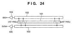
- Fig. 24 shows a configuration of a linear CCD image sensor used in a conventional image reading apparatus.
- reference numeral 101 denotes a photoreceptive pixel array of the linear CCD image sensor; 102 and 103, analog shift registers for sequentially reading charges stored in the odd- and even-number pixels of the photoreceptive pixel array 101, respectively; and 104 and 105, output amplifiers for converting the charges read from the analog shift registers 102 and 103 into voltage signals and outputs the signals.
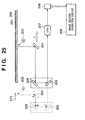
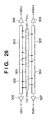
- Fig. 25 shows an example of a configuration of an image reading apparatus which uses a linear image sensor of the aforesaid type (referred to as "E/O type linear sensor", hereinafter).
- reference numeral 208 denotes a linear image sensor (here, an E/O type linear sensor); 201, a platen glass; 202, an original; 203, an illumination lamp for illuminating the original; 204 to 206, first to third mirrors, respectively; 207, a lens for forming an image of the original on the photoreceptive surface of the E/O type linear sensor 208; 209, an image sensor operation circuit for operating the E/O type linear sensor 208; and 210, a white board to be read for obtaining reference data used in shading correction processing.
- a linear image sensor here, an E/O type linear sensor
- 201 a platen glass
- 202 an original
- 203 an illumination lamp for illuminating the original
- 204 to 206 first to third mirrors, respectively
- 207 a lens for forming an image of the original on the photoreceptive surface of the E/O type linear sensor 208
- 209 an image sensor operation circuit for operating the E/O type linear sensor 208
- the illumination lamp 203 and the first to third mirrors 204 to 206 are at the position indicated by the solid lines when performing a normal reading operation of reading the original, whereas, they moves to the position indicated by the dot lines when reading the white board 210. Further, the first to third mirrors 204 to 206 move in the sub-scanning direction S when reading the original, thereby reading the original in two dimensions.
- the reason of separately reading charges accumulated in the even- and odd-number pixels of the photoreceptive pixel array 101 is that there is a limitation in transfer speed in the analog shift registers 102 and 103, and it is necessary to do so to achieve a scan speed faster than a predetermined speed.
- reference numeral 301 denotes a photoreceptive pixel array of the linear CCD image sensor; 302 to 305, analog shift registers for sequentially reading the charges accumulated in the even- and odd-number pixels in the right- and left-side areas of the photoreceptive pixel array 301; and 306 to 309, output amplifiers for converting the charges read out from the analog shift registers 302, 304, 303 and 305, respectively, into voltage signals and outputting them.
- the analog shift registers 302 to 305 of the R/L type linear sensor shown in Fig. 26 respectively read out charges accumulated in the odd-number pixels in the left-side area, charges accumulated in the odd-number pixels in the right-side area, charges accumulated in the even-number pixels in the left-side area, and charges accumulated in the even-number pixels in the right-side area of the photoreceptive pixel array 301.
- Fig. 27 shows a timing chart of operation signals for the R/L type linear sensor shown in Fig. 26 and the output signals from the R/L type linear sensor.
- SH shows a charge shift pulse and controls gates for simultaneously transferring charges accumulated in the photoreceptive pixel array 301 to the analog shift registers 302 to 305. Therefore, as shown in Fig. 27 , a period between one SH pulse and the next SH pulse is an accumulation period (Tint) for accumulating charges in the photoreceptive pixel array 301.
- ⁇ 1 and ⁇ 2 in Fig. 27 are charge transfer pulses for operating the analog shift registers 302 to 305, and sequentially transferring the charges, by pixel, which has been simultaneously transferred from the photoreceptive pixel array 301 to the analog shift registers 302 to 305 by the SH pulse toward the output amplifiers 306 to 309 arranged at the end of each of the analog shift registers 302 to 305.
- image signals indicated by ODD-1, EVEN-1, ODD-2, and EVEN-2 are outputted.
- Document EP 0 808 057 A2 discloses an apparatus for and a method of correcting an output signal of a linear image sensor.
- the odd- and even-numbered pixel level difference correction process can produce corrected image data whose waveform center of gravity remains positionally unshifted unlike a conventional correction process which corrects a pixel signal using only the pixel signal to be corrected and the preceding pixel signal
- document EP 0 901 277 A2 discloses an image processing apparatus and method.
- the characteristic curve for line B unpreferably has a stepwise characteristic portion having a step when it is stored in an LUT, due to quantization errors unique to digital values.
- the characteristic curve for line A is set to be decreased by the amount corresponding to the step.
- the present invention has been made in consideration of the above situation, and has as its object to reduce signal level differences that are a defect of a R/L type sensor used for realizing a high-speed scan operation, and to match linearity between respective output channels.
- document EP 0 878 958 A2 shows a method and device for image density correction for a CCD sensor.
- an AGC-MO circuit which is connected to an output terminal OS1 operates to make an electric current of a predetermined value flow into a differential amplifying circuit with use of the differential amplifying circuit, a terminal-based detection circuit, the other differential amplifying circuits, a comparison circuit, a reference control value, a reference current generating circuit, and a voltage holding circuit.
- the comparison result obtained by the comparison circuit is output to the AGC-S1, AGC-S2, and the AGC-S3 circuit, as a reference value of the AGC circuits.
- the difference in image density of the image obtained by the quadruplex CCD is corrected by the AGC-S1 circuit connected to an output terminal OS2, the AGC-S2 circuit connected to an output terminal OS3, and the AGC-S3 circuit connected to an output terminal OS4.
- document US 5,148,296 A discloses an original document reading apparatus.
- An original document recording apparatus has a plurality of line sensors arranged in a uniformly staggered pattern.
- Each line sensor has a built-in analog memory, which stores the image and outputs the image according to a delay value.
- the built-in analog memory is controlled by two kinds of pulse-train signals generated by a control means, thus reducing a vertical delay time.
- document JP-A-11027524 discloses a scanner and signal processing method to attain proper shading correction with a simple configuration by scanning a reference image for several times and using its mean value as reference data.
- a line sensor scans a black/write reference board, an analog signal processing section processes an image, an A/D converter converts the result into a digital signal, and the digital signal is fed to a digital signal processing section.
- An address of each base area of R, G, B signals of a 1 st pixel of an image signal is read from a memory and the R, G, B signals are rewritten in each address. Such a processing is conducted for 1 st , 5 th , 9 th and 13 th line periods to obtain a signal for each pixel equipment to worth 4 liners.
- the data are read from a work area and accumulated to obtain a mean value of the data equipment to 4 lines for a period of 18 th to 20 th as the reference data.
- the reference data without fluctuation in the linear sensor and noise are obtained, while the capacity of the memory required for the processing is set constant.
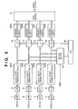
- Figs. 1 to 3 shows a configuration of an image reading apparatus according to the present invention.
- reference numeral 1 to 4 denote amplifiers for amplifying output signals from an R/L type linear sensor as shown in Fig. 26 ; 5 to 8, A/D converters for converting output signals amplified by the amplifiers 1 to 4 to digital signals; 9 to 12, black offset/shading correction circuits for performing black offset correction by subtracting black offset level from the digital signals and performing shading correction.
- LUTs 13 to 16 as discrepancy correction means are for realizing discrepancy correction (correcting level differences in signals) of the right and left signals by adjusting signal levels of ODD-1, EVEN-1, ODD-2 and EVEN-2.
- a first memory 17 is used for temporarily storing signals output from the R/L type linear sensor at timing shown in Fig. 27 , and rearranging the order of the signals to the order of pixels, and outputting the rearranged signals, and a second memory 19 temporarily stores pixel data so that a CPU 30 can fetch pixel data during the "High" period of a signal PHEN shown in Fig. 27 .
- the contents to be set in the LUTs 13 to 16 for discrepancy correction are determined from obtained image data by performing operations (will be described later).
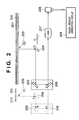
- Fig. 2 shows a schematic configuration of the image reading apparatus of the present invention.
- the image reading apparatus shown in Fig. 2 differs from the conventional image reading apparatus shown in Fig. 25 in that it has a gray reference board 701 and a R/L type linear sensor is used instead of an E/O type linear sensor.
- reference numeral 208 denotes a linear image sensor (here, a R/L type linear sensor as described above); 201, a platen glass; 202, an original; 203, an illumination lamp for illuminating the original; 204 to 206, first to third mirrors, respectively; 207, a lens for forming an image of the original on the photoreceptive surface of the R/L type linear sensor 208; 209, an image sensor operation circuit for operating the R/L type linear sensor 208; and 210 a white board to be read for obtaining reference data used in shading correction processing.
- a linear image sensor here, a R/L type linear sensor as described above
- 201 a platen glass
- 202 an original
- 203 an illumination lamp for illuminating the original
- 204 to 206 first to third mirrors, respectively
- 207 a lens for forming an image of the original on the photoreceptive surface of the R/L type linear sensor 208
- 209 an image sensor operation circuit for operating the R/
- the illumination lamp 203 and the first to third mirrors 204 to 206 are at the position indicated by the solid lines when performing a normal reading operation of reading the original and moves to the position indicated by the dot lines when reading the gray reference board 701 and the white board 210. Further, the first to third mirrors move in the sub-scanning direction S when reading the original, thereby reading the original in two dimensions.
- the gray reference board 701 is a board colored in gray (a non-chromatic color between white and black).
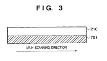
- the gray reference board 701 and white board 210 for shading correction are arranged side by side, however, they may be configured on a single board as shown in Fig. 3 .
- Fig. 4A is a graph showing an example of ODD-1 signal and ODD-2 signal before the discrepancy correction (LUT conversion) is applied.
- the abscissa represents brightness of an original
- the ordinate represents signal levels of read image signals. Since ODD-1 and ODD-2 signals are outputted via different output amplifiers 306 and 308 of the R/L type linear sensor and further amplified by different amplifiers 1 and 3, then converted to digital signals by different A/D converters 5 and 7, respectively, signals obtained by reading the original of the same brightness have slightly different signal levels.
- Fig. 4A only shows ODD-1 and ODD-2 signals, and other two signals EVEN-1 and EVEN-2 respectively have slightly different linearity from the linearity of ODD-1 and ODD-2 signals.
- the LUTs 13 to 16 as the discrepancy correction means are to match signal levels of the four channels for brightness by correcting levels of signals output from the four channels to a predetermined linearity as shown in Fig. 4B . It is possible to match signal levels of the ODD-1 and ODD-2 signals in this manner, and the rest of the signals, namely, EVEN-1 and EVEN-2 signals can be corrected in the same manner, thereby matching signal levels of all the channels.
- a predetermined accumulation period is set in step S101, then an image is read using the gray reference board 701 shown in Fig. 2 in step S102.
- the accumulation period in the R/L type linear sensor 208 is changed (step S104) and the gray reference board 701 is read each time after the accumulation period is changed until step S103 becomes "Yes" (i.e., a predetermined number of times), thereby obtaining signal levels corresponding to the different accumulation periods.
- Fig. 5 shows an example of data obtained from one channel by scanning the gray reference board 701.
- the abscissa represents accumulation period (Tint) and the ordinate represents signal levels obtained by scanning the gray reference board 701.
- T accumulation period
- the ordinate represents signal levels obtained by scanning the gray reference board 701.
- data for each of accumulation periods which are integer multiples of a predetermined period T are shown, however, any accumulation periods may be used.
- Image data obtained by reading the gray reference board 701 for different accumulation periods are stored in the second memory 19, and CPU 20 read the image data stored in the second memory 19, averages the image data for the respective channels, thereby obtaining signal levels of the respective channels.
- the graph shown in Fig. 5 is obtained by repeating the aforesaid processing for different accumulation periods nT (n is an integer). Therefore, the graph of Fig. 5 shows the linearity characteristics of one of the channels (step S105).
- Fig. 7 shows a graph showing conversion characteristics of a LUT used for correcting the linearity characteristics shown in Fig. 5 to an ideal linearity. The conversion characteristics may be obtained by inverting the characteristics shown in Fig. 5 .
- the linearity of each channel of the R/L type linear sensor is changed to an ideal linearity, however, the linearity to which the linearity of each channel is changed may be any predetermined linearity since discrepancy correction of image signals output from the R/L type linear image sensor is the purpose of the correction in the first explanatory example.
- CPU 20 sets the discrepancy correction data obtained as described above to the LUTs 13 and 15 in Fig. 1 (step S107), thus levels of read ODD-1 and ODD-2 signals are corrected.
- Gap correction data for the EVEN-1 and EVEN-2 signals may be calculated in the same manner, and by setting the obtained discrepancy correction data to the LUTs 14 and 16, levels of read EVEN-1 and EVEN-2 signals can be also corrected.
- the LUTs as discrepancy connection circuits are arranged downstream to the shading correction circuits according to the first explanatory example. This is because the discrepancy correction means realize not only discrepancy correction but also linearity correction, and by arranging the discrepancy correction means downstream to the shading correction circuits, it is possible to achieve stable linearity independent of main scanning position.
- the discrepancy correction means are arranged downstream to the shading correction circuits.
- signals output from the respective channels are applied with shading correction first, then discrepancy correction next, so that linearity of the signals from the respective channels match. Therefore, when the quantity of light emitted by the illumination lamp changes and gains used in shading correction change, there is a possibility that correction data used in the linearity correction may become inappropriate.
- an image reading apparatus has a configuration as shown in Fig. 9 .
- the configuration shown in Fig. 9 differs from that shown Fig. 1 explained in the first embodiment in that the LUTs 13 to 16 as discrepancy correction means for performing discrepancy correction are arranged upstream to shading correction circuits 1305 to 1308.
- Black offset correction circuits 1301 to 1304 process read signals before the discrepancy correction is performed by the LUTs 13 to 16.
- the black offset correction is performed before or after the discrepancy correction by the LUTs 13 to 16 does not limit the present invention, and either is possible.
- the discrepancy correction means upstream to the shading correction circuits, linearity of signals output from the respective channels are corrected before the shading correction is performed. Accordingly, when the quantity of light emitted by the illumination lamp of the image reading apparatus has changed, stable discrepancy correction is achieved.
- the discrepancy correction is performed using LUTs in the first and second explanatory examples, however, the discrepancy correction may be realized by generating operation equations for converting linearity and converting the linearity of read signals from the respective channels by using these operation equations.
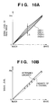
- Fig. 10A shows relationship between signal levels of the respective channels before performing the linearity correction (e.g., LUT conversion).
- the abscissa represents brightness of an original
- the ordinate represents signal levels of read image.
- the black level of each channel is corrected in black level correction
- the white level is corrected in shading correction by the black offset/shading correction circuits 9 to 12. Accordingly, there are not much difference in black and white signal levels between the respective channels.
- signal levels corresponding to the intermediate brightness vary among the channels. This is because the amplifiers and A/D converters which process output signals of the respective channels are different from each other, and slight difference in linearity characteristics can not be avoid.
- the LUT 13 to 16 change signal levels of the respective channels corresponding to the same brightness to a predetermined linearity, as shown in Fig. 10B , thereby matching the linearity of the respective channels.
- the averages of signal level of pixels in the vicinity of the connection portion for the respective channels are calculated for the white board 210 and the gray reference board 701 shown in Fig. 2 , as shown in a flowchart of Fig. 22 .
- the white board 210 and the gray reference board 701 are read first as described above (steps S301 and S302), and the read image data are temporally stored in the second memory 19. Thereafter, the CPU 20 reads the image data from the second memory 19 and averages the image data of the pixels in the vicinity of the connection portion for each channel.
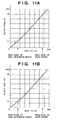
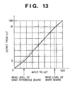
- the CPU 20 generates a linearity correction table as shown in Fig. 11A or 11B for each channel from the averages of signal levels, obtained by reading the white board 210 and the gray reference board 701, of the pixels in the vicinity of the connection portion (step S303), then sets it to corresponding one of the LUTs 13 to 16 (step S304).
- Figs. 11A and 11B illustrate graphs showing examples of linearity characteristics set in a LUT when the image data is 10-bit image data.
- the abscissas represent a signal level input to the LUT
- the ordinates represent a signal level output from the LUT.
- 11A and 11B show contents of a LUT having characteristics for converting the average of signal levels obtained by reading the gray reference board 701 to a reference level G which is an expected value to be obtained by reading the gray reference board (referred to as “gray reference level”, hereinafter), and converting the average of signal levels obtained by reading the white board 210 to a reference level W which is an expected value to be obtained by reading the white board (referred to as "white reference level”, hereinafter).
- Fig. 11A shows a case of interpolating the contents of the conversion table between the read levels of the gray reference board 701 and of the white board 210 with two straight lines
- Fig. 11B shows a case of interpolating the contents with a curve.
- various arithmetic functions such as an exponential function and an n-th degree function, may be used for interpolation by fitting.
- the white reference level W and the gray reference level G are predetermined.
- the white reference level is set to an ideal level, in advance, which is an expected level to be ideally obtained by reading the white board 210. This value corresponds to the design of the image reading apparatus.
- the gray reference level G is set in the similar manner. In this case, the white reference level W and the gray reference reveal G are predetermined constants.
- the white reference level W and the gray reference level G are calculated from read levels of the respective channels.
- the read level of the white board 210 and the gray reference board 701 are, Channels Read Level of White Board Read Level of Gray reference board ODD-1 W1 G1 ODD-2 W2 G2 EVEN-1 W3 G3 EVEN-2 W4 G4 then, the white reference level W is obtained in any of the methods (1) to (3), and the gray reference level G is obtained in any of the methods (4) to (6).
- the maximum LUT output of A channel which is one of the ODD-1, ODD-2, EVEN-1 and EVEN-2 is "1023", however, the maximum LUT output of B channel, different from the A channel, is smaller than "1023".
- the obtained white levels may differ from each other.
- the LUT conversion it is necessary to set the contents of the LUTs 13 to 16 so that the maximum level (saturation level) of a signal after the LUT conversion is not smaller than the maximum level (saturation level) of a signal before the LUT conversion.
- the gray reference board 701 upon calculating the LUT contents to be used in the linearity correction, the gray reference board 701 is needed in addition to the white board 210 for shading correction, which increases the cost and size of the image reading apparatus.
- the image reading apparatus 100' does not have the gray reference board 701, as shown in Fig. 14 . Instead, a reference chart 113 having a uniform density is placed on the platen glass, and the LUT contents are calculated using the chart. In this case, the image reading apparatus 100' calculates the LUT contents by reading the reference chart 113 and the white board 210 in response to an instruction by an instruction unit (not shown).
- the processing sequence according to the fourth embodiment is as shown in Fig. 23 .
- the reference chart 113 placed on the platen glass is scanned at step S402 in Fig. 23 .
- Other processes are same as those shown in Fig. 22 , and the explanation of them is omitted.
- a uniform density pattern as shown in Fig. 15A and a step pattern (made of plurality of uniform density colors) as shown in Fig. 15B may be considered.
- a step pattern made of plurality of uniform density colors
- Fig. 15B since it is possible to scan different tones, more reference points which may be used for calculation of LUT contents can be obtained. Accordingly, LUT contents of improved precision for correction can be calculated.
- the white reference level W and gray reference levels corresponding to the respective tones on the reference chart 113 (here, G1 to G4) may be set in the same manner as described in the first embodiment.
- the reference chart 113 the one which is generated by a personal computer and printed by a printer, for instance, may be used. However, it is necessary to optically blur the black dots printed by the printer to make the density uniform. Therefore, any supporting member for supporting the chart slightly above the platen glass may be used so as not to directly place the printed reference chart on the platen glass. Another glass may be placed on the platen glass instead of using the supporting member.
- a test print or a copy print printed by the printer 200 may be used.
- the charts as shown in Figs. 15A and 15B may be used as the reference chart 113.
- a supporting member would better be used for supporting the chart slightly above the platen glass so as not to directly place the chart on the platen glass, as described above.
- Fig. 18 shows an example of a configuration of a color linear image sensor according to the third embodiment.
- reference numeral 1601 denotes a photoreceptive unit for red (R), 1602, a photoreceptive unit for green (G), and 1603, a photoreceptive unit for blue (B). Signals from each photoreceptive unit are separately read for even- and odd-number pixels in the right-side area, and for and even- and odd-number pixels in the left-side area, similarly to the configuration shown in Fig. 26 .
- a unit shown in Fig. 1 for adjusting discrepancy in signal levels of pixels between the right- and left-side areas is provided.
- the unit works in a similar manner as described in one of the first to second explanatory examples as first to second embodiments.
- the input signal ODD-1 in Fig. 1 represents one of RO1, GO1 and BO1 output from the R, G and B photoreceptive units 1601 to 1603, EVEN-1 represents corresponding one of RE1, GE1 and BE1, ODD-2 represents corresponding one of RO1, RO2, GO2 and BO2, and EVEN-2 represents corresponding one of RE1, RE2, GE2 and BE2.
- Fig. 19 shows an configuration of an interline type area image sensor according to the fourth embodiment of the present invention.
- reference numeral 1701 denotes each of photoreceptive pixels; 1702, a vertical transfer CCD; 1703 and 1704, horizontal transfer CCD which transfers changes to the left and right, respectively, with respect to the center; and 1705 and 1706, output amplifiers.
- signals from the photoreceptive pixels 1701 included in the left-side area of the area image sensor are transferred by the horizontal transfer CCD 1703 and outputted via the output amplifier 1705.
- signals from the photoreceptive pixels 1702 included in the right-side area are transferred by the horizontal transfer CCD 1704 and outputted via the output amplifier 1706.
- An area image sensor of this type can be easily manufactured. It should be noted that a frame transfer type (progressive scanning type) area sensor may be used instead of the interline type area sensor.
- Fig. 20 shows a configuration of a processing system for the R/L type area image sensor shown in Fig. 19 .
- reference numeral 1801 and 1802 denote amplifiers for signals of right- and left-side areas separately output from the respective channels read out (Outputs A and B from the amplifiers 1705 and 1706 in Fig. 19 .
- a and B channels respectively, hereinafter
- reference numeral 1809 denotes a first memory for changing the order of the separately read image signals via the A and B channels to the order of pixels for combining the image signals.
- Reference numeral 1810 denotes a second memory.
- the CPU 1811 can set a conversion table to the LUTs 1807 and 1808 calculated by referring to the second memory 1802.
- an iris diaphragm is provided in front of the area image sensor, by changing aperture of the iris diaphragm, if an illumination device is provided, by changing the quantity of illumination light, and if the area sensor has an electronic shutter function, by changing exposure time using the electronic shutter, it is possible to obtain different signal levels. In these cases, the white board and gray reference board are not needed.
- the present invention can be applied to a system constituted by a plurality of devices (e.g., host computer, interface, reader, printer) or to an apparatus comprising a single device (e.g., scanner, CCD camera, copying machine, facsimile machine).
- devices e.g., host computer, interface, reader, printer
- apparatus comprising a single device (e.g., scanner, CCD camera, copying machine, facsimile machine).
- the object of the present invention can also be achieved by providing a storage medium storing program codes for performing the aforesaid processes to a computer system or apparatus (e.g., a personal computer), reading the program codes, by a CPU or MPU of the computer system or apparatus, from the storage medium, then executing the program.
- a computer system or apparatus e.g., a personal computer
- the program codes read from the storage medium realize the functions according to the embodiments, and the storage medium storing the program codes constitutes the invention.
- the storage medium such as a floppy disk, a hard disk, an optical disk, a magneto-optical disk, CD-ROM, CD-R, a magnetic tape, a non-volatile type memory card, and ROM can be used for providing the program codes.
- the present invention includes a case where an OS (operating system) or the like working on the computer performs a part or the entire processes in accordance with designations of the program codes and realize functions according to the above embodiments.
- the present invention also includes a case where, after the program codes read from the storage medium are written in a function expansion card which is inserted into the computer or in a memory provided in a function expansion unit which is connected to the computer, CPU or the like contained in the function expansion card or unit performs a part or the entire process in accordance with designations of the program codes and realizes functions of the above embodiments.
- the storage medium stores program codes corresponding to any of the flowcharts shown in Figs. 21 to 23 described in the embodiments.
Landscapes
- Engineering & Computer Science (AREA)
- Multimedia (AREA)
- Signal Processing (AREA)
- Facsimile Image Signal Circuits (AREA)
- Facsimile Scanning Arrangements (AREA)
- Image Input (AREA)
Claims (83)
- Bilderfassungsvorrichtung mit:einem Bildsensor (301 bis 309, 1601 bis 1603, 1701 bis 1706), der Bildsignale (ODD-1, ODD-2, EVEN-1, EVEN-2) von einer Vielzahl von geteilten Bereichen einer Vielzahl von photorezeptiven Bildelementen aus einer Vielzahl von Ausgabeanschlüssen separat ausgibt, die jeweils der Vielzahl von geteilten Bereichen entsprechen,gekennzeichnet durch:eine Referenzpegelberechnungseinrichtung (20, 1811), die zu einem Berechnen eines ersten Referenzpegels auf der Grundlage der von jedem der Vielzahl von geteilten Bereichen des Bildsensors ausgegebenen Bildsignale, wenn ein weißer Referenzabschnitt (210) durch den Bildsensor abgetastet wird, und zu einem Berechnen eines zweiten Referenzpegels auf der Grundlage der von jedem der Vielzahl von geteilten Bereichen des Bildsensors ausgegebenen Bildsignale, wenn ein eine vorbestimmte Halbtondichte aufweisender Referenzdichtenabschnitt (701, 113) durch den Bildsensor abgetastet wird, konfiguriert ist, undeine Einstellungseinrichtung (1 bis 12, 1801 bis 1806), die zu einem unabhängigen und im Wesentlichen gleichzeitigen Einstellen von von jeweils von der Vielzahl von Ausgabeanschlüssen ausgegebenen Bildsignalen konfiguriert ist, um 1) Pegel der von den jeweiligen geteilten Bereichen ausgegebenen Bildsignale mit dem ersten Referenzpegel im Wesentlichen abzugleichen, wenn der weiße Referenzabschnitt abgetastet wird, und um 2) Pegel der von den jeweiligen geteilten Bereichen ausgegebenen Bildsignale mit dem zweiten Referenzpegel im Wesentlichen abzugleichen, wenn der Referenzdichtenabschnitt abgetastet wird.
- Bilderfassungsvorrichtung gemäß Anspruch 1, wobei die Einstellungseinrichtung (13 bis 16, 1807, 1808) Pegel der von den Ausgabeanschlüssen ausgegebenen Bildsignale (ODD-1, ODD-2, EVEN-1, EVEN-2) unter Verwendung von Nachschlagetabellen einstellt.
- Bilderfassungsvorrichtung gemäß Anspruch 1, wobei die Einstellungseinrichtung (13 bis 16, 1807, 1808) die Pegel der von den Ausgabeanschlüssen ausgegebenen Bildsignale (ODD-1, ODD-2, EVEN-1, EVEN-2) unter Verwendung von Operationsgleichungen einstellt.
- Bilderfassungsvorrichtung gemäß Anspruch 1, wobei die Einstellungseinrichtung (13 bis 16, 1807, 1808) Pegel der von den Ausgabeanschlüssen ausgegebenen Bildsignale (ODD-1, ODD-2, EVEN-1, EVEN-2) einstellt, um den Pegel des vorbestimmten Referenzsignals auf der Grundlage von Daten im Wesentlichen abzugleichen, die durch Lesen des Referenzdichtenelements (701, 113) durch den Bildsensor (301 bis 309, 1601 bis 1603, 1701 bis 1706) während einer Änderung einer Akkumulationsspanne erhalten werden.
- Bilderfassungsvorrichtung gemäß Anspruch 4, wobei die Einstellungseinrichtung (13 bis 16, 1807, 1808) die Pegel der von den Ausgabeanschlüssen ausgegebenen Bildsignale (ODD-1, ODD-2, EVEN-1, EVEN-2) auf der Grundlage von Pegeln einstellt, die durch Abziehen eines während der Akkumulationsspanne ausgegebenen Dunkelstrompegels, der zum Lesen des Referenzdichtenelements (701, 113) verwendet wird, von den Pegeln der von den Ausgabeanschlüssen ausgegebenen Bildsignale (ODD-1, ODD-2, EVEN-1, EVEN-2) erhalten werden.
- Bilderfassungsvorrichtung gemäß Anspruch 1, ferner mit einer Schattierungskorrektureinrichtung (9 bis 12), wobei die Einstellungseinrichtung (13 bis 16, 1807, 1808) der Schattierungskorrektureinrichtung nachliegend angeordnet ist.
- Bilderfassungsvorrichtung gemäß Anspruch 1, ferner mit einer Schattierungskorrektureinrichtung (1305 bis 1308), wobei die Einstellungseinrichtung (13 bis 16, 1807, 1808) der Schattierungskorrektureinrichtung vorausgehend angeordnet ist.
- Bilderfassungsvorrichtung gemäß Anspruch 1, ferner mit:einer Schattierungskorrektureinrichtung, undeinem Schalter zum Ändern einer Verarbeitungsreihenfolge der Einstellungseinrichtung (13 bis 16, 1807, 1808) und der Schattierungskorrektureinrichtung.
- Bilderfassungsvorrichtung gemäß Anspruch 1, wobei der Bildsensor (301 bis 309, 1601 bis 1603, 1701 bis 1706) Signale eines rechtsseitig geteilten Bereichs separat von Signalen eines linksseitig geteilten Bereichs ausgibt.
- Bilderfassungsvorrichtung gemäß Anspruch 1, wobei der Bildsensor (301 bis 309, 1601 bis 1603, 1701 bis 1706) ein linearer Bildsensor (301 bis 309, 1601 bis 1603) ist.
- Bilderfassungsvorrichtung gemäß Anspruch 10, wobei eine Vielzahl der linearen Bildsensoren (1601 bis 1603), die jeweils einer Vielzahl von Farben entsprechen, bereitgestellt ist, um einen Farbbildsensor (301 bis 309, 1601 bis 1603, 1701 bis 1706) auszubilden.
- Bilderfassungsvorrichtung gemäß Anspruch 1, wobei der Bildsensor (301 bis 309, 1601 bis 1603, 1701 bis 1706) ein Flächenbildsensor (701 bis 1706) ist.
- Bilderfassungsvorrichtung gemäß Anspruch 1, wobei das Referenzdichtenelement (701) innerhalb der Bilderfassungsvorrichtung bereitgestellt ist.
- Bilderfassungsvorrichtung gemäß Anspruch 1, ferner mit einer Platte zum Platzieren eines zu lesenden Originals auf der Platte, wobei die Steuereinrichtung (209) den Bildsensor (301 bis 309, 1601 bis 1603, 1701 bis 1706) steuert, um das Referenzdichtenelement (701, 113) in einem Fall zu lesen, in welchem das Referenzdichtenelement (701, 113) auf der Platte platziert wird.
- Bilderfassungsvorrichtung gemäß Anspruch 1, wobei die Bilderfassungsvorrichtung mit einem Drucker verbunden ist und das Referenzdichtenelement (701, 113) durch den Drucker gedruckt wird.
- Bilderfassungsvorrichtung gemäß Anspruch 15, wobei die Bilderfassungsvorrichtung einstückig mit dem Drucker ausgebildet ist.
- Bilderfassungsverfahren in einer Bilderfassungsvorrichtung mit einem Bildsensor (301 bis 309, 1601 bis 1603, 1701 bis 1706), der Bildsignale (ODD-1, PDD- 2, EVEN-1, EVEN-2) von einer Vielzahl von geteilten Bereichen einer Vielzahl von photorezeptiven Bildelementen aus einer Vielzahl von Ausgabeanschlüssen separat ausgibt, die jeweils der Vielzahl von geteilten Bereichen entsprechen,
einem Referenzpegelberechnungsschritt des Berechnens eines ersten Referenzpegels auf der Grundlage der von jedem der Vielzahl von geteilten Bereichen des Bildsensors (301 bis 309, 1601 bis 1603, 1701 bis 1706) ausgegebenen Bildsignale, wenn ein weißer Referenzabschnitt (210) durch den Bildsensor (301 bis 309, 1601 bis 1603, 1701 bis 1706) abgetastet wird, und des Berechnens eines zweiten Referenzpegels auf der Grundlage der von jedem der Vielzahl von geteilten Bereichen des Bildsensors (301 bis 309, 1601 bis 1603, 1701 bis 1706) ausgegebenen Bildsignale (ODD-1, ODD-2, EVEN-1, EVEN-2), wenn ein eine vorbestimmte Halbtondichte aufweisender Referenzdichtenabschnitt (701, 133) durch den Bildsensor (301 bis 309, 1601 bis 1603, 1701 bis 1706) abgetastet wird, und
einem Einstellungsschritt (S105- S107) des unabhängigen und im Wesentlichen gleichzeitigen Einstellens von jeweils von der Vielzahl von Ausgabeanschlüssen ausgegebenen Bildsignalen (ODD-1, ODD-2, EVEN-1, EVEN-2), um 1) Pegel der von den jeweiligen geteilten Bereichen ausgegebenen Bildsignale (301 bis 309, 1601 bis 1603, 1701 bis 1706) mit dem ersten Referenzpegel im Wesentlichen abzugleichen, wenn der weiße Referenzabschnitt abgetastet wird, und um 2) Pegel der von den jeweiligen geteilten Bereichen ausgegebenen Bildsignale mit dem zweiten Referenzpegel im Wesentlichen abzugleichen, wenn der Referenzdichtenabschnitt abgetastet wird. - Bilderfassungsverfahren gemäß Anspruch 17, wobei in dem Einstellungsschritt Nachschlagetabellen der Verarbeitungseinrichtung gesetzt werden, um die Pegel der von den Ausgabeanschlüssen ausgegebenen Bildsignale (ODD-1, ODD-2, EVEN-1, EVEN-2) einzustellen.
- Bilderfassungsverfahren gemäß Anspruch 17, wobei in dem Einstellungsschritt Operationsgleichungen in der Verarbeitungseinrichtung gesetzt werden, um die Pegel der von den Ausgabeanschlüssen ausgegebenen Bildsignale unter Verwendung von Operationsgleichungen einzustellen.
- Bilderfassungsverfahren gemäß Anspruch 17, wobei in dem Einstellungsschritt die Verarbeitungseinrichtung eingestellt wird, um die Pegel der von den Ausgabeanschlüssen ausgegebenen Bildsignale (ODD-1, ODD-2, EVEN-1, EVEN-2) mit dem Pegel des vorbestimmten Referenzsignals auf der Grundlage von Daten im Wesentlichen abzugleichen, die durch Lesen des Referenzdichtenelements (701, 113) durch den Bildsensor (301 bis 309, 1601 bis 1603, 1701 bis 1706) während einer Änderung einer Akkumulationsspanne erhalten werden.
- Bilderfassungsverfahren gemäß Anspruch 20, wobei in dem Einstellungsschritt Pegel, die durch Abziehen eines während der Akkumulationsspanne ausgegebenen Dunkelstrompegels, der zum Lesen des Referenzdichtenelements (701, 113) verwendet wird, von den Pegeln der von den Ausgabeanschlüssen ausgegebenen Bildsignale (ODD-1, ODD-2, EVEN-1, EVEN-2) erhalten werden, mit dem Pegel des vorbestimmten Referenzsignals abgeglichen werden.
- Bilderfassungsverfahren gemäß Anspruch 17, ferner mit einem Schattierungskorrekturschritt, wobei der Einstellungsschritt nach dem Schattierungskorrekturschritt durchgeführt wird.
- Bilderfassungsverfahren gemäß Anspruch 17, ferner mit einem Schattierungskorrekturschritt, wobei der Einstellungsschritt vor dem Konvertierungskorrekturschritt durchgeführt wird.
- Bilderfassungsverfahren gemäß Anspruch 17, ferner mit:einem Schattierungskorrekturschritt, undeinem Schaltschritt des Änderns einer Verarbeitungsreihenfolge des Einstellungsschritts und des Schattierungskorrekturschritts.
- Bilderfassungsverfahren gemäß Anspruch 17, wobei der Bildsensor (301 bis 309, 1601 bis 1603, 1701 bis 1706) Signale eines rechtsseitig geteilten Bereichs separat von Signalen eines linksseitig geteilten Bereichs ausgibt.
- Bilderfassungsverfahren gemäß Anspruch 17, wobei der Bildsensor (301 bis 309, 1601 bis 1603, 1701 bis 1706) ein linearer Bildsensor (301 bis 309, 1601 bis 1603) ist.
- Bilderfassungsverfahren gemäß Anspruch 26, wobei die Bilderfassungsvorrichtung eine Vielzahl der linearen Bildsensoren (301 bis 309, 1601 bis 1603) aufweist, die jeweils einer Vielzahl von Farben entsprechen, um einen Farbbildsensor (301 bis 309, 1601 bis 1603, 1701 bis 1706) auszubilden.
- Bilderfassungsverfahren gemäß Anspruch 17, wobei der Bildsensor (301 bis 309, 1601 bis 1603, 1701 bis 1706) ein Flächenbildsensor (701 bis 1706) ist.
- Bilderfassungsverfahren gemäß Anspruch 17, wobei das Referenzdichtenelement (701, 113) innerhalb der Bilderfassungsvorrichtung bereitgestellt ist.
- Bilderfassungsverfahren gemäß Anspruch 17, wobei die Bilderfassungsvorrichtung ferner eine Platte zum Platzieren eines zu lesendes Originals auf der Platte enthält, und in dem Leseschritt (S102) das auf der Platte platzierte Referenzdichtenelement (701, 113) gelesen wird.
- Bilderfassungsverfahren gemäß Anspruch 17, wobei die Bilderfassungsvorrichtung mit einem Drucker verbunden ist und das Bilderfassungsverfahren ferner einen Schritt des Druckens des Referenzdichtenelements (701, 113) durch den Drucker aufweist.
- Bilderfassungsverfahren gemäß Anspruch 17, wobei die Bilderfassungsvorrichtung einstückig mit dem Drucker ausgebildet ist.
- Computerprogrammprodukt mit einem computerverwendbaren Medium, das eine in dem Medium gefasste computerlesbare Programmcodeeinrichtung für ein Bildleseverfahren in einer Bilderfassungsvorrichtung aufweist, die einen Bildsensor (301 bis 309, 1601 bis 1603, 1701 bis 1706) aufweist, der Bildsignale (ODD-1, ODD-2, EVEN-1, EVEN-2) von einer Vielzahl von geteilten Bereichen einer Vielzahl von photorezeptiven Bildelementen aus einer Vielzahl von Ausgabeanschlüssen separat ausgibt, die jeweils der Vielzahl von geteilten Bereichen entsprechen, mit:einer ersten computerlesbaren Programmcodeeinrichtung, die zu einem Berechnen eines ersten Referenzpegels auf der Grundlage der von jedem der Vielzahl von geteilten Bereichen des Bildsensors (301 bis 309, 1601 bis 1603, 1701 bis 1706) ausgegebenen Bildsignale (ODD-1, ODD-2, EVEN-1, EVEN-2), wenn ein weißer Referenzabschnitt (210) durch den Bildsensor (301 bis 309, 1601 bis 1603, 1701 bis 1706) abgetastet wird, und zu einem Berechnen eines zweiten Referenzpegels auf der Grundlage der von jedem der Vielzahl von geteilten Bereichen des Bildsensor (301 bis 309, 1601 bis 1603, 1701 bis 1706) ausgegebenen Bildsignale (ODD-1, ODD-2, EVEN-1, EVEN-2), wenn ein eine vorbestimmte Halbtondichte aufweisender Referenzdichtenabschnitt (701, 113) durch den Bildsensor (301 bis 309, 1601 bis 1603, 1701 bis 1706) abgetastet wird, konfiguriert ist, undeiner zweiten computerlesbaren Programmcodeeinrichtung, die zu einem unabhängigen und im Wesentlichen gleichzeitigen Einstellen von jeweils von der Vielzahl von Ausgabeanschlüssen ausgegebenen Bildsignalen (ODD-1, ODD-2, EVEN-1, EVEN-2) konfiguriert ist, um 1) Pegel der von den jeweiligen geteilten Bereichen ausgegebenen Bildsignale (ODD-1, ODD-2, EVEN-1, EVEN-2) mit dem ersten Referenzpegel im Wesentlichen abzugleichen, wenn der weiße Referenzabschnitt abgetastet wird, und um 2) Pegel der von den jeweiligen geteilten Bereichen ausgegebenen Bildsignale (ODD-1, ODD-2, EVEN-1, EVEN-2) mit dem zweiten Referenzpegel im Wesentlichen abzugleichen, wenn der Referenzdichtenabschnitt abgetastet wird.
- Bilderfassungsvorrichtung gemäß Anspruch 1, ferner mit:einer Vielzahl von Signalverarbeitungseinrichtungen (1 bis 12, 1801 bis 1806), die jeweils der Vielzahl von geteilten Bereichen entsprechen, zum Anwenden einer vorbestimmten Signalverarbeitung bei den von den Ausgabeanschlüssen ausgegebenen Bildsignalen (ODD-1, ODD-2, EVEN-1, EVEN-2),einer weißen Tafel (210), undeiner Einstellungsdatengewinnungseinrichtung (20, 1811), die zu einem Gewinnen von Einstellungsdaten für die jeweiligen Signalverarbeitungseinrichtungen (1 bis 12) konfiguriert ist, zum 1) im Wesentlichen Abgleichen von Pegeln der von der Vielzahl von Signalverarbeitungseinrichtungen (1 bis 12) ausgegebenen Bildsignale (ODD-1, ODD-2, EVEN-1, EVEN-2) mit einem ersten vorbestimmten Pegel, wenn die weiße Tafel (210) abgetastet wird, zum 2) im Wesentlichen Abgleichen von Pegeln der von der Vielzahl von Signalverarbeitungseinrichtungen (1 bis 12) ausgegebenen Bildsignale (ODD-1, ODD-2, EVEN-1, EVEN-2) mit einem zweiten vorbestimmten Pegel, der das vorbestimmte Referenzsignal ist, wenn die Referenzdichtenplatte abgetastet wird, und zum 3) im Wesentlichen Abgleichen von Pegeln der von der Vielzahl von Signalverarbeitungseinrichtung (1 bis 12) ausgegebenen Bildsignale mit einem Pegel, der durch Interpolieren zwischen den ersten und zweiten vorbestimmten Pegeln erhalten wird, wenn ein Bild mit einer Dichte, die von der Dichte der weißen Tafel (210) verschieden ist, und die Referenzdichtenplatte abgetastet werden, wobei die Einstellungseinrichtung (13 bis 16, 1807, 1808) der Einstellungsdatengewinnungseinrichtung nachliegend angeordnet ist.
- Bilderfassungsvorrichtung gemäß Anspruch 34, wobei das Referenzdichtenelement (701) innerhalb der Bilderfassungsvorrichtung bereitgestellt ist.
- Bilderfassungsvorrichtung gemäß Anspruch 34, ferner mit einer Platte zum Platzieren eines zu lesendes Originals auf der Platte,
wobei die Steuereinrichtung (209) den Bildsensor (301 bis 309, 1601 bis 1603, 1701 bis 1706) steuert, um das Referenzdichtenelement (701, 113) in einem Fall zu lesen, in welchem das Referenzdichtenelement (701, 113) auf der Platte platziert wird. - Bilderfassungsvorrichtung gemäß Anspruch 34, wobei zumindest einer der ersten und zweiten vorbestimmten Pegel vorab eingestellt wird.
- Bilderfassungsvorrichtung gemäß Anspruch 34, wobei der erste vorbestimmte Pegel eine Mittelung von Signalpegeln ist, die von der Vielzahl von Signalverarbeitungseinrichtungen (1 bis 12) erhalten werden, wenn die weiße Tafel (210) abgetastet wird.
- Bilderfassungsvorrichtung gemäß Anspruch 34, wobei der erste vorbestimmte Pegel ein Maximum von Signalpegeln ist, die von der Vielzahl von Signalverarbeitungseinrichtungen (1 bis 12) erhalten werden, wenn die weiße Tafel (210) abgetastet wird.
- Bilderfassungsvorrichtung gemäß Anspruch 34, wobei der erste vorbestimmte Pegel ein Minimum von Signalpegeln ist, die von der Vielzahl von Signalverarbeitungseinrichtungen (1 bis 12) erhalten werden, wenn die weiße Tafel (210) abgetastet wird.
- Bilderfassungsvorrichtung gemäß Anspruch 34, wobei der zweite vorbestimmte Pegel eine Mittelung von Signalpegeln ist, die von der Vielzahl von Signalverarbeitungseinrichtungen (1 bis 12) erhalten werden, wenn die Referenzdichtenplatte abgetastet wird.
- Bilderfassungsvorrichtung gemäß Anspruch 34, wobei der zweite vorbestimmte Pegel ein Maximum von Signalpegeln ist, die von der Vielzahl von Signalverarbeitungseinrichtungen (1 bis 12) erhalten werden, wenn die Referenzdichtenplatte abgetastet wird.
- Bilderfassungsvorrichtung gemäß Anspruch 34, wobei der zweite vorbestimmte Pegel ein Minimum von Signalpegeln ist, die von der Vielzahl von Signalverarbeitungseinrichtungen (1 bis 12) erhalten werden, wenn die Referenzdichtenplatte abgetastet wird.
- Bilderfassungsvorrichtung gemäß Anspruch 34, wobei der erste vorbestimmte Pegel ein Maximum von Signalpegeln ist, die von der Vielzahl von Signalverarbeitungseinrichtungen (1 bis 12) erhalten werden, wenn die weiße Tafel (210) abgetastet wird, und der zweite vorbestimmte Pegel ein Minimum von Signalpegeln ist, die von der Vielzahl von Signalverarbeitungseinrichtungen (1 bis 12) erhalten werden, wenn die Referenzdichtenplatte abgetastet wird.
- Bilderfassungsvorrichtung gemäß Anspruch 34, wobei die Einstellungsdatengewinnungseinrichtung die Einstellungsdaten derart gewinnt, dass maximale Pegel von von der Vielzahl von Signalverarbeitungseinrichtungen (1 bis 12) erhaltenen Bildsignalen (ODD-1, ODD-2, EVEN-1, EVEN-2) nach einer Einstellung durch die Einstellungseinrichtung (13 bis 16, 1807, 1808) maximale Pegel werden.
- Bilderfassungsvorrichtung gemäß Anspruch 34, wobei die Pegel zwischen den ersten und zweiten vorbestimmten Pegeln durch eine gerade Linie interpoliert werden.
- Bilderfassungsvorrichtung gemäß Anspruch 34, wobei die Pegel zwischen den ersten und zweiten vorbestimmten Pegeln durch eine Kurve interpoliert werden.
- Bilderfassungsvorrichtung gemäß Anspruch 34, wobei die Interpolation durch eine Operation durchgeführt wird.
- Bilderfassungsvorrichtung gemäß Anspruch 34, wobei die Einstellungsdaten in Form einer Nachschlagetabelle vorliegen.
- Bilderfassungsvorrichtung gemäß Anspruch 34, wobei der Bildsensor Signale eines rechtsseitig geteilten Bereichs separat von Signalen eines linksseitig geteilten Bereichs ausgibt.
- Bilderfassungsvorrichtung gemäß Anspruch 34, wobei der Bildsensor (301 bis 309, 1601 bis 1603, 1701 bis 1706) ein linearer Bildsensor (301 bis 309, 1601 bis 1603) ist.
- Bilderfassungsvorrichtung gemäß Anspruch 51, wobei eine Vielzahl der linearen Bildsensoren (1601 bis 1603), die jeweils einer Vielzahl von Farben entsprechen, bereitgestellt ist, um einen Farbbildsensor (301 bis 309, 1601 bis 1603, 1701 bis 1706) auszubilden.
- Bilderfassungsvorrichtung gemäß Anspruch 34, wobei der Bildsensor (301 bis 309, 1601 bis 1603, 1701 bis 1706) ein Flächenbildsensor (701 bis 1706) ist.
- Bilderfassungsvorrichtung gemäß Anspruch 34, wobei jede der Vielzahl von Signalverarbeitungseinrichtungen (1 bis 12) einen Verstärker (1 bis 4) zum Verstärken des von dem Ausgabeanschluss ausgegebenen Bildsignals enthält.
- Bilderfassungsvorrichtung gemäß Anspruch 34, wobei jede der Vielzahl von Signalverarbeitungseinrichtungen (1 bis 12) einen A/D- Umwandler (5 bis 8) zum Umwandeln des von dem Ausgabeanschluss ausgegebenen Bildsignals von einem analogen Signal in ein digitales Signal enthält.
- Bilderfassungsvorrichtung gemäß Anspruch 36, wobei die Bilderfassungsvorrichtung mit einem Drucker verbunden ist und das Referenzdichtenelement (701, 113) durch den Drucker gedruckt wird.
- Bilderfassungsvorrichtung gemäß Anspruch 34, wobei das Referenzdichtenelement (701, 113) zumindest einen Abschnitt uniformer Dichte aufweist.
- Bilderfassungsvorrichtung gemäß Anspruch 56, wobei die Bilderfassungsvorrichtung einstückig mit dem Drucker ausgebildet ist.
- Bilderfassungsverfahren gemäß Anspruch 17, wobei die Bilderfassungsvorrichtung eine Vielzahl von Signalverarbeitungseinrichtungen (1 bis 12), die jeweils der Vielzahl von geteilten Bereichen entsprechen, zum Anwenden einer vorbestimmten Signalverarbeitung bei den von den Ausgabeanschlüssen ausgegebenen Bildsignalen (301 bis 309, 1601 bis 1603, 1701 bis 1706) und eine weiße Tafel (210) aufweist, mit den Schritten:einem ersten Leseschritt (S301) des Abtastens der weißen Tafel (210) durch den Bildsensor (301 bis 309, 1601 bis 1603, 1701 bis 1706) und des Ausgebens von durch die Vielzahl von Signalverarbeitungseinrichtungen (1 bis 12) verarbeiteten Bildsignalen (ODD-1, ODD-2, EVEN-1, EVEN-2),einem zweiten Leseschritt (S302, S402) des Abtastens der Referenzdichtenplatte durch den Bildsensor (301 bis 309, 1601 bis 1603, 1701 bis 1706) und des Ausgebens von durch die Vielzahl von Signalverarbeitungseinrichtungen (1 bis 12) verarbeiteten Bildsignalen (ODD-1, ODD-2, EVEN-1, EVEN-2),einem Einstellungsdatengewinnungsschritt (S303) des Gewinnens von Einstellungsdaten für die jeweiligen Signalverarbeitungseinrichtungen (1 bis 12) zum 1) im Wesentlichen Abgleichen von Pegeln der in dem ersten Leseschritt (S301) ausgegebenen Bildsignale (ODD-1, ODD-2, EVEN-1, EVEN-2) mit einem ersten vorbestimmten Pegel, zum 2) im Wesentlichen Abgleichen von Pegeln der in dem zweiten Leseschritt (S302, S402) ausgegebenen Bildsignale (ODD-1, ODD-2, EVEN-1, EVEN-2) mit einem zweiten vorbestimmten Pegel, der das vorbestimmte Referenzsignal ist, und zum 3) im Wesentlichen Abgleichen von Pegeln der von der Vielzahl von Signalverarbeitungseinrichtungen (1 bis 12) ausgegebenen Bildsignale (ODD-1, ODD-2, EVEN-1, EVEN-2) mit einem Pegel, der durch Interpolieren zwischen den ersten und zweiten vorbestimmten Pegeln erhalten wird, wenn ein Bild mit einer Dichte, die von der Dichte der weißen Tafel (210) verschieden ist, und die Referenzdichtenplatte auf der Grundlage der Bildsignale (ODD-1, ODD-2, EVEN-1, EVEN-2) abgetastet werden, die in den ersten und zweiten Leseschritten (S301, S302; S402) erhalten werden, wobeider Einstellungsschritt Pegel von von der Vielzahl von Signalverarbeitungseinrichtungen (1 bis 12) ausgegebenen Bildsignalen (ODD-1, ODD-2, EVEN-1, EVEN-2) unter Verwendung der Einstellungsdaten einstellt.
- Einstellungsverfahren gemäß Anspruch 59, wobei das Referenzdichtenelement (701) innerhalb der Bilderfassungsvorrichtung bereitgestellt ist.
- Einstellungsverfahren gemäß Anspruch 59, wobei die Bilderfassungsvorrichtung ferner eine Platte zum Platzieren eines zu lesenden Originals auf der Platte umfasst,
und in dem zweiten Leseschritt (S302, S402) das auf der Platte platzierte Referenzdichtenelement (701, 113) gelesen wird. - Einstellungsverfahren gemäß Anspruch 59, wobei zumindest einer der ersten und zweiten vorbestimmten Pegel vorab eingestellt wird.
- Einstellungsverfahren gemäß Anspruch 59, ferner mit einem Schritt des Berechnens einer Mittelung von Signalpegeln, die von der Vielzahl von Signalverarbeitungseinrichtungen (1 bis 12) in dem ersten Leseschritt (S301) erhalten werden, als der erste vorbestimmte Pegel.
- Einstellungsverfahren gemäß Anspruch 59, ferner mit einem Schritt des Gewinnes eines Maximums von Signalpegeln, die von der Vielzahl von Signalverarbeitungseinrichtungen (1 bis 12) in dem ersten Leseschritt (S301) erhalten werden, als der erste vorbestimmte Pegel.
- Einstellungsverfahren gemäß Anspruch 59, ferner mit einem Schritt des Gewinnes eines Minimums von Signalpegeln, die von der Vielzahl von Signalverarbeitungseinrichtungen (1 bis 12) in dem ersten Leseschritt (S301) erhalten werden, als der erste vorbestimmte Pegel.
- Einstellungsverfahren gemäß Anspruch 59, ferner mit einem Schritt des Berechnens einer Mittelung von Signalpegeln, die von der Vielzahl von Signalverarbeitungseinrichtungen (1 bis 12) in dem zweiten Leseschritt (S302, S402) erhalten werden, als der zweite vorbestimmte Pegel.
- Einstellungsverfahren gemäß Anspruch 59, ferner mit einem Schritt des Gewinnes eines Maximums von Signalpegeln, die von der Vielzahl von Signalverarbeitungseinrichtungen (1 bis 12) in dem zweiten Leseschritt (S302, S402) erhalten werden, als der zweite vorbestimmte Pegel.
- Einstellungsverfahren gemäß Anspruch 59, ferner mit einem Schritt des Gewinnes eines Minimums von Signalpegeln, die von der Vielzahl von Signalverarbeitungseinrichtungen (1 bis 12) in einem zweiten Leseschritt (S302, S402) erhalten werden, als der zweite vorbestimmte Pegel.
- Einstellungsverfahren gemäß Anspruch 59, ferner mit:einem Schritt des Gewinnes eines Maximums von Signalpegeln, die von der Vielzahl von Signalverarbeitungseinrichtung (1 bis 12) in dem ersten Leseschritt (S301) erhalten werden, als der erste vorbestimmte Pegel, undeinem Schritt des Gewinnes eines Minimums von Signalpegeln, die von der Vielzahl von Signalverarbeitungsvorrichtungen (1 bis 12) in dem zweiten Leseschritt (S302, S402) erhalten werden, als der zweite vorbestimmte Pegel.
- Einstellungsverfahren gemäß Anspruch 59, wobei in dem Einstellungsdatengewinnungsschritt die Einstellungsdaten derart gewonnen werden, dass maximale Pegel von von der Vielzahl von Signalverarbeitungseinrichtungen (1 bis 12) erhaltenen Bildsignalen (301 bis 309, 1601 bis 1603, 1701 bis 1706) nach einer Einstellung durch die Einstellungseinrichtung (13 bis 16, 1807, 1808) maximale Pegel werden.
- Einstellungsverfahren gemäß Anspruch 59, wobei die Pegel zwischen den ersten und zweiten vorbestimmten Pegeln durch eine gerade Linie interpoliert werden.
- Einstellungsverfahren gemäß Anspruch 59, wobei die Pegel zwischen den ersten und zweiten vorbestimmten Pegeln durch eine Kurve interpoliert werden.
- Einstellungsverfahren gemäß Anspruch 59, wobei die Interpolation durch eine Operation durchgeführt wird.
- Einstellungsverfahren gemäß Anspruch 59, wobei die Einstellungsdaten in Form einer Nachschlagetabelle vorliegen.
- Einstellungsverfahren gemäß Anspruch 59, wobei der Bildsensor Signale eines rechtsseitig geteilten Bereichs separat von Signalen eines linksseitig geteilten Bereichs ausgibt.
- Einstellungsverfahren gemäß Anspruch 59, wobei der Bildsensor (301 bis 309, 1601 bis 1603, 1701 bis 1706) ein linearer Bildsensor (301 bis 309, 1601 bis 1603) ist.
- Einstellungsverfahren gemäß Anspruch 46, wobei in der Bilderfassungsvorrichtung eine Vielzahl der linearen Bildsensoren (1601 bis 1603), die jeweils einer Vielzahl von Farben entsprechen, bereitgestellt sind, um einen Farbbildsensor (301 bis 309, 1601 bis 1603, 1701 bis 1706) auszubilden.
- Einstellungsverfahren gemäß Anspruch 59, wobei der Bildsensor (301 bis 309, 1601 bis 1603, 1701 bis 1706) ein Flächenbildsensor (701 bis 1706) ist.
- Einstellungsverfahren gemäß Anspruch 59, wobei jede der Vielzahl von Signalverarbeitungseinrichtungen (1 bis 12) einen Verstärker (1 bis 4) zum Verstärken des von dem Ausgabeanschluss ausgegebenen Bildsignals enthält.
- Einstellungsverfahren gemäß Anspruch 59, wobei jede der Vielzahl von Signalverarbeitungseinrichtungen (1 bis 12) einen A/D- Umwandler (5 bis 8) zum Umwandeln des von dem Ausgabeanschluss ausgegebenen Bildsignals von einem analogen Signal in ein digitales Signal enthält.
- Einstellungsverfahren gemäß Anspruch 61, wobei die Bilderfassungsvorrichtung mit einem Drucker verbunden ist und das Einstellungsverfahren ferner einen Schritt des Druckens des Referenzdichtenelements (701, 113) durch den Drucker aufweist.
- Einstellungsverfahren gemäß Anspruch 59, wobei das Referenzdichtenelement (701, 113) zumindest einen Abschnitt uniformer Dichte aufweist.
- Computerprogrammprodukt gemäß Anspruch 33, wobei die Bilderfassungsvorrichtung eine Vielzahl von Signalverarbeitungseinrichtungen (1 bis 12), die jeweils der Vielzahl von geteilten Bereichen entsprechen, zum Anwenden einer vorbestimmten Signalverarbeitung bei den von den Ausgabeanschlüssen ausgegebenen Bildsignalen (ODD-1, ODD-2, EVEN-1, EVEN-2) und eine weiße Tafel (210) aufweist, mit:einer vierten computerlesbaren Programmcodeeinrichtung, die zum Abtasten der weißen Tafel (210) durch den Bildsensor (301 bis 309, 1601 bis 1603, 1701 bis 1706) und zum Ausgeben von durch die Vielzahl von Signalverarbeitungseinrichtungen (1 bis 12) verarbeiteten Bildsignalen (ODD-1, ODD-2, EVEN-1, EVEN-2) konfiguriert ist,einer fünften computerlesbaren Pogrammcodeeinrichtung, die zum Abtasten der Referenzdichtenplatte durch den Bildsensor (301 bis 309, 1601 bis 1603, 1701 bis 1706) und zum Ausgeben von durch die Vielzahl von Signalverarbeitungseinrichtungen (1 bis 12) verarbeiteten Bildsignalen (ODD-1, ODD-2, EVEN-1, EVEN-2) konfiguriert ist,einer sechsten computerlesbaren Programmcodeeinrichtung, die zu einem Gewinnen von Einstellungsdaten für die jeweiligen Signalverarbeitungseinrichtungen (1 bis 12) konfiguriert ist, zum 1) im Wesentlichen Abgleichen von Pegeln der von der Vielzahl von Signalverarbeitungseinrichtungen (1 bis 12) ausgegebenen Bildsignale (ODD-1, ODD-2, EVEN-1, EVEN-2) mit einem ersten vorbestimmten Pegel, wenn die weiße Tafel (210) abgetastet wird, zum 2) im Wesentlichen Abgleichen von Pegeln der von der Vielzahl von Signalverarbeitungseinrichtungen (1 bis 12) ausgegebenen Bildsignale (ODD-1, ODD-2, EVEN-1, EVEN-2) mit einem zweiten vorbestimmten Pegel, der das vorbestimmte Referenzsignal ist, wenn die Referenzdichtenplatte abgetastet wird, und zum 3) im Wesentlichen Abgleichen von Pegeln der von der Vielzahl von Signalverarbeitungseinrichtungen (1 bis 12) ausgegebenen Bildsignale (ODD-1, ODD-2, EVEN-1, EVEN-2) mit einem Pegel, der durch Interpolieren zwischen den ersten und zweiten vorbestimmten Pegeln erhalten wird, wenn ein Bild mit einer Dichte, die von der Dichte der weißen Tafel (210) verschieden ist, und die Referenzdichtenplatte abgetastet werden, wobeidie dritte computerlesbare Programmcodeeinrichtung zu einem Einstellen von Pegeln von von der Vielzahl von Signalverarbeitungseinrichtungen (1 bis 12) ausgegebenen Bildsignalen (ODD-1, ODD-2, EVEN-1, EVEN-2) unter Verwendung der Einstellungsdaten konfiguriert ist.
Applications Claiming Priority (6)
| Application Number | Priority Date | Filing Date | Title |
|---|---|---|---|
| JP2000024389 | 2000-02-01 | ||
| JP2000024389A JP2001217990A (ja) | 2000-02-01 | 2000-02-01 | 画像読み取り装置及び画像読み取り方法 |
| JP2000166394 | 2000-06-02 | ||
| JP2000166394A JP2001346012A (ja) | 2000-06-02 | 2000-06-02 | 画像読取装置及び画像信号の調整方法 |
| JP2001015744 | 2001-01-24 | ||
| JP2001015744A JP2002218186A (ja) | 2001-01-24 | 2001-01-24 | 撮像装置及び画像信号の調整方法 |
Publications (3)
| Publication Number | Publication Date |
|---|---|
| EP1137255A2 EP1137255A2 (de) | 2001-09-26 |
| EP1137255A3 EP1137255A3 (de) | 2004-05-06 |
| EP1137255B1 true EP1137255B1 (de) | 2008-06-18 |
Family
ID=27342207
Family Applications (1)
| Application Number | Title | Priority Date | Filing Date |
|---|---|---|---|
| EP01102273A Expired - Lifetime EP1137255B1 (de) | 2000-02-01 | 2001-01-31 | Korrekturverfahren und -vorrichtung für Bildsignale die durch einen Bildsensor mit mehreren Ausgangskanälen erzeugt wurden |
Country Status (3)
| Country | Link |
|---|---|
| US (1) | US7324236B2 (de) |
| EP (1) | EP1137255B1 (de) |
| DE (1) | DE60134441D1 (de) |
Families Citing this family (24)
| Publication number | Priority date | Publication date | Assignee | Title |
|---|---|---|---|---|
| CN1244222C (zh) * | 2001-08-22 | 2006-03-01 | 佳能株式会社 | 成像区域包括多个区域的成像传感装置输出的信号的处理 |
| JP2003134307A (ja) * | 2001-10-26 | 2003-05-09 | Canon Inc | 画像読取装置 |
| DE10242516A1 (de) * | 2002-09-12 | 2004-03-25 | Bts Media Solutions Gmbh | Verfahren und Anordnung zur Korrektur von Videosignalen |
| US7379104B2 (en) * | 2003-05-02 | 2008-05-27 | Canon Kabushiki Kaisha | Correction apparatus |
| JP4340503B2 (ja) * | 2003-09-18 | 2009-10-07 | 株式会社リコー | 原稿読取装置 |
| US7359090B2 (en) * | 2003-12-22 | 2008-04-15 | Lexmark International, Inc. | Shading an optical sensing element such as in a scanner |
| US7605951B2 (en) * | 2004-02-10 | 2009-10-20 | Ricoh Company, Ltd. | Image reader, image forming and reproducing apparatus, and image reading method |
| JP2005348351A (ja) * | 2004-06-07 | 2005-12-15 | Ricoh Co Ltd | 画像読取装置及び画像形成装置 |
| JP2007158663A (ja) * | 2005-12-05 | 2007-06-21 | Ricoh Co Ltd | アナログ画像信号のオフセット調整方法 |
| US8953233B2 (en) | 2010-06-14 | 2015-02-10 | Canon Kabushiki Kaisha | Image reading apparatus and image data processing method |
| US9918017B2 (en) | 2012-09-04 | 2018-03-13 | Duelight Llc | Image sensor apparatus and method for obtaining multiple exposures with zero interframe time |
| US8878256B2 (en) | 2013-01-07 | 2014-11-04 | Semiconductor Components Industries, Llc | Image sensors with multiple output structures |
| US8878255B2 (en) | 2013-01-07 | 2014-11-04 | Semiconductor Components Industries, Llc | Image sensors with multiple output structures |
| CN105794115B (zh) * | 2013-10-31 | 2019-12-31 | 统雷有限公司 | 多通道匹配方法 |
| JP6152819B2 (ja) * | 2014-03-31 | 2017-06-28 | ブラザー工業株式会社 | 画像読取装置 |
| US12401911B2 (en) | 2014-11-07 | 2025-08-26 | Duelight Llc | Systems and methods for generating a high-dynamic range (HDR) pixel stream |
| US9432552B2 (en) | 2014-11-10 | 2016-08-30 | Brother Kogyo Kabushiki Kaisha | Image scanning apparatus |
| US12401912B2 (en) | 2014-11-17 | 2025-08-26 | Duelight Llc | System and method for generating a digital image |
| US12445736B2 (en) | 2015-05-01 | 2025-10-14 | Duelight Llc | Systems and methods for generating a digital image |
| JP2017079374A (ja) * | 2015-10-19 | 2017-04-27 | 株式会社リコー | 画像読取装置、画像形成装置、およびシェーディングデータ処理方法 |
| US9846951B2 (en) * | 2016-03-31 | 2017-12-19 | Konica Minolta Laboratory U.S.A., Inc. | Determining a consistent color for an image |
| CN107454971B (zh) * | 2017-07-17 | 2019-01-25 | 深圳市汇顶科技股份有限公司 | 光学感应校正参数的确定方法、生物特征检测装置和电子终端 |
| RU2715292C1 (ru) * | 2019-01-31 | 2020-02-26 | ФЕДЕРАЛЬНОЕ ГОСУДАРСТВЕННОЕ КАЗЕННОЕ ВОЕННОЕ ОБРАЗОВАТЕЛЬНОЕ УЧРЕЖДЕНИЕ ВЫСШЕГО ОБРАЗОВАНИЯ "Военная академия Ракетных войск стратегического назначения имени Петра Великого" МИНИСТЕРСТВА ОБОРОНЫ РОССИЙСКОЙ ФЕДЕРАЦИИ | Способ и устройство обработки оптической информации |
| EP3805942A1 (de) | 2019-10-11 | 2021-04-14 | Palantir Technologies Inc. | Verwaltung von objektdaten |
Family Cites Families (39)
| Publication number | Priority date | Publication date | Assignee | Title |
|---|---|---|---|---|
| JPH01171361A (ja) | 1987-12-25 | 1989-07-06 | Fuji Xerox Co Ltd | 原稿読取装置 |
| JPH02148972A (ja) | 1988-11-29 | 1990-06-07 | Fuji Photo Film Co Ltd | 画像信号補正方法および装置 |
| JPH0344267A (ja) | 1989-07-12 | 1991-02-26 | Mitsubishi Electric Corp | 画像読取方法 |
| US5284746A (en) | 1990-02-08 | 1994-02-08 | Zymogenetics, Inc. | Methods of producing hybrid G protein-coupled receptors |
| IE20020110A1 (en) | 1990-09-13 | 2003-05-28 | Univ Duke | Expression of G Protein Coupled Receptors in Yeast |
| JPH04225681A (ja) | 1990-12-27 | 1992-08-14 | Toppan Printing Co Ltd | 画像入力方法およびその装置 |
| US5371613A (en) * | 1991-02-22 | 1994-12-06 | Canon Kabushiki Kaisha | Image reading apparatus |
| US5576436A (en) | 1991-08-01 | 1996-11-19 | Pharmaceutical Discovery Corporation | Fluorescent ligands |
| AU2407192A (en) | 1991-08-01 | 1993-03-02 | Pharmaceutical Discovery Corporation | Characterization of specific drug receptors with fluorescent ligands |
| WO1993007294A1 (en) | 1991-10-01 | 1993-04-15 | The United States Of America, Represented By The Secretary, Department Of Health And Human Service | A method of identifying ligands and antagonists of ligands |
| JPH05130399A (ja) * | 1991-10-31 | 1993-05-25 | Canon Inc | 原稿読取装置 |
| JPH05191575A (ja) | 1992-01-16 | 1993-07-30 | Ricoh Co Ltd | 画像読取装置 |
| DE69325854T2 (de) * | 1992-05-26 | 1999-12-23 | United Parcel Service Of America, Inc. | Verfahren und System zur Zielbilderkennung |
| US5366889A (en) | 1992-11-30 | 1994-11-22 | The General Hospital Corporation | DNA encoding a protein-coupled receptor kinase |
| US5542031A (en) * | 1993-04-30 | 1996-07-30 | Douglass; Clay S. | Halftone computer imager |
| US5491084A (en) | 1993-09-10 | 1996-02-13 | The Trustees Of Columbia University In The City Of New York | Uses of green-fluorescent protein |
| US5644409A (en) * | 1994-01-13 | 1997-07-01 | Mita Industrial Co., Ltd. | Shading correcting method and shading correcting apparatus for use in image forming apparatuses |
| JPH07250341A (ja) * | 1994-03-11 | 1995-09-26 | Asahi Optical Co Ltd | 電子カメラのホワイトバランス調整装置 |
| JPH099063A (ja) * | 1995-06-21 | 1997-01-10 | Brother Ind Ltd | 画像読み取り転送方法及びその転送システム |
| US6043909A (en) * | 1996-02-26 | 2000-03-28 | Imagicolor Corporation | System for distributing and controlling color reproduction at multiple sites |
| JP3348167B2 (ja) * | 1996-03-26 | 2002-11-20 | シャープ株式会社 | 画像2値化装置 |
| JP3738080B2 (ja) | 1996-05-17 | 2006-01-25 | 富士写真フイルム株式会社 | リニアイメージセンサの出力信号補正装置 |
| US5989835A (en) | 1997-02-27 | 1999-11-23 | Cellomics, Inc. | System for cell-based screening |
| JPH1042111A (ja) | 1996-07-26 | 1998-02-13 | Ricoh Co Ltd | 画像読取装置 |
| US5960110A (en) * | 1996-10-15 | 1999-09-28 | Fuji Photo Film Co., Ltd. | Method of establishing conversion relationship for color prediction |
| JPH10224574A (ja) | 1997-02-12 | 1998-08-21 | Minolta Co Ltd | 画像読取装置 |
| JPH10233921A (ja) | 1997-02-19 | 1998-09-02 | Seiko Epson Corp | 原稿読取装置 |
| JP3177187B2 (ja) | 1997-05-14 | 2001-06-18 | 株式会社東芝 | 補正装置と補正方法と画像読取装置と画像形成装置 |
| JPH1127524A (ja) | 1997-07-01 | 1999-01-29 | Sony Corp | スキャナ装置および信号処理方法 |
| JPH1188687A (ja) | 1997-09-05 | 1999-03-30 | Canon Inc | 画像処理装置及び画像処理方法 |
| JP3766192B2 (ja) | 1997-11-13 | 2006-04-12 | 株式会社東芝 | 光電変換装置、光電変換方法、画像情報処理装置、画像情報処理方法、および画像形成装置 |
| JPH11215298A (ja) | 1998-01-22 | 1999-08-06 | Toshiba Corp | 画像情報処理装置と画像情報処理方法と画像形成装置 |
| JP3940489B2 (ja) | 1998-03-13 | 2007-07-04 | 株式会社東芝 | 画像読み取り装置及び方法 |
| JPH11275321A (ja) | 1998-03-19 | 1999-10-08 | Pfu Ltd | 画像読取装置 |
| JP2000078375A (ja) | 1998-09-03 | 2000-03-14 | Toshiba Corp | 画像形成装置 |
| JP2000078397A (ja) | 1998-09-03 | 2000-03-14 | Toshiba Corp | 画像形成装置 |
| JP2000151904A (ja) | 1998-11-13 | 2000-05-30 | Pfu Ltd | 画像読取り装置およびその制御方法ならびにその記録媒体 |
| JP2000188670A (ja) | 1998-12-22 | 2000-07-04 | Toshiba Corp | 画像読取装置 |
| JP4031132B2 (ja) | 1998-12-22 | 2008-01-09 | 株式会社東芝 | 画像形成装置 |
-
2001
- 2001-01-30 US US09/772,664 patent/US7324236B2/en not_active Expired - Fee Related
- 2001-01-31 EP EP01102273A patent/EP1137255B1/de not_active Expired - Lifetime
- 2001-01-31 DE DE60134441T patent/DE60134441D1/de not_active Expired - Lifetime
Also Published As
| Publication number | Publication date |
|---|---|
| US20010030770A1 (en) | 2001-10-18 |
| EP1137255A2 (de) | 2001-09-26 |
| EP1137255A3 (de) | 2004-05-06 |
| US7324236B2 (en) | 2008-01-29 |
| DE60134441D1 (de) | 2008-07-31 |
Similar Documents
| Publication | Publication Date | Title |
|---|---|---|
| EP1137255B1 (de) | Korrekturverfahren und -vorrichtung für Bildsignale die durch einen Bildsensor mit mehreren Ausgangskanälen erzeugt wurden | |
| US7423784B2 (en) | Processing of signals from image sensing apparatus whose image sensing area includes a plurality of areas | |
| JP3809226B2 (ja) | リニアイメージセンサの出力画像信号の補正方法 | |
| EP0557099A1 (de) | Bildverarbeitungsgerät | |
| US5535007A (en) | Method and device for adjusting magnification of image | |
| EP0632644A2 (de) | Einrichtung und Verfahren für die Kompensation von Offset- und Verstärkungsdrift, die während einer Datenkommunikation auftritt | |
| US6175660B1 (en) | Image reading apparatus | |
| US7605951B2 (en) | Image reader, image forming and reproducing apparatus, and image reading method | |
| US7327500B2 (en) | Image inputting apparatus | |
| EP1615421B1 (de) | Bildabtaster | |
| JP2002218186A (ja) | 撮像装置及び画像信号の調整方法 | |
| US6965463B1 (en) | Image reading apparatus | |
| US7889404B2 (en) | Image reading device, image forming apparatus, and reading-unit install method | |
| EP0808057A2 (de) | Verfahren und Vorrichtung zum Korrigieren eines Ausgangssignals eines Zeilensensors | |
| JP2003219172A (ja) | 画像処理装置及び画像形成装置 | |
| JP2001346012A (ja) | 画像読取装置及び画像信号の調整方法 | |
| JP4085956B2 (ja) | 撮像装置 | |
| JP4414276B2 (ja) | 画像読取装置 | |
| JP3150033B2 (ja) | カラースキャナ | |
| JP4121981B2 (ja) | 画像読取装置 | |
| KR100242025B1 (ko) | 쉐이딩 보정을 이용한 칼라 화상 스캐닝 장치 및 방법 | |
| JP4173452B2 (ja) | 画像読取装置、画像形成装置及び画像読取方法 | |
| JP2003274122A (ja) | オリジナルイメージから電気的イメージ信号を生成する装置 | |
| JP4070026B2 (ja) | 画像処理装置及び同装置に用いるプログラム | |
| JP2006025286A (ja) | 画像読取装置及び画像形成装置 |
Legal Events
| Date | Code | Title | Description |
|---|---|---|---|
| PUAI | Public reference made under article 153(3) epc to a published international application that has entered the european phase |
Free format text: ORIGINAL CODE: 0009012 |
|
| AK | Designated contracting states |
Kind code of ref document: A2 Designated state(s): AT BE CH CY DE DK ES FI FR GB GR IE IT LI LU MC NL PT SE TR |
|
| AX | Request for extension of the european patent |
Free format text: AL;LT;LV;MK;RO;SI |
|
| PUAL | Search report despatched |
Free format text: ORIGINAL CODE: 0009013 |
|
| AK | Designated contracting states |
Kind code of ref document: A3 Designated state(s): AT BE CH CY DE DK ES FI FR GB GR IE IT LI LU MC NL PT SE TR |
|
| AX | Request for extension of the european patent |
Extension state: AL LT LV MK RO SI |
|
| 17P | Request for examination filed |
Effective date: 20040916 |
|
| AKX | Designation fees paid |
Designated state(s): DE FR GB NL |
|
| 17Q | First examination report despatched |
Effective date: 20050113 |
|
| GRAP | Despatch of communication of intention to grant a patent |
Free format text: ORIGINAL CODE: EPIDOSNIGR1 |
|
| GRAS | Grant fee paid |
Free format text: ORIGINAL CODE: EPIDOSNIGR3 |
|
| GRAA | (expected) grant |
Free format text: ORIGINAL CODE: 0009210 |
|
| AK | Designated contracting states |
Kind code of ref document: B1 Designated state(s): DE FR GB NL |
|
| REG | Reference to a national code |
Ref country code: GB Ref legal event code: FG4D |
|
| REF | Corresponds to: |
Ref document number: 60134441 Country of ref document: DE Date of ref document: 20080731 Kind code of ref document: P |
|
| PG25 | Lapsed in a contracting state [announced via postgrant information from national office to epo] |
Ref country code: NL Free format text: LAPSE BECAUSE OF FAILURE TO SUBMIT A TRANSLATION OF THE DESCRIPTION OR TO PAY THE FEE WITHIN THE PRESCRIBED TIME-LIMIT Effective date: 20080618 |
|
| NLV1 | Nl: lapsed or annulled due to failure to fulfill the requirements of art. 29p and 29m of the patents act | ||
| PLBE | No opposition filed within time limit |
Free format text: ORIGINAL CODE: 0009261 |
|
| STAA | Information on the status of an ep patent application or granted ep patent |
Free format text: STATUS: NO OPPOSITION FILED WITHIN TIME LIMIT |
|
| 26N | No opposition filed |
Effective date: 20090319 |
|
| REG | Reference to a national code |
Ref country code: FR Ref legal event code: PLFP Year of fee payment: 16 |
|
| REG | Reference to a national code |
Ref country code: FR Ref legal event code: PLFP Year of fee payment: 17 |
|
| PGFP | Annual fee paid to national office [announced via postgrant information from national office to epo] |
Ref country code: DE Payment date: 20170131 Year of fee payment: 17 Ref country code: FR Payment date: 20170126 Year of fee payment: 17 |
|
| PGFP | Annual fee paid to national office [announced via postgrant information from national office to epo] |
Ref country code: GB Payment date: 20170130 Year of fee payment: 17 |
|
| REG | Reference to a national code |
Ref country code: DE Ref legal event code: R119 Ref document number: 60134441 Country of ref document: DE |
|
| GBPC | Gb: european patent ceased through non-payment of renewal fee |
Effective date: 20180131 |
|
| PG25 | Lapsed in a contracting state [announced via postgrant information from national office to epo] |
Ref country code: FR Free format text: LAPSE BECAUSE OF NON-PAYMENT OF DUE FEES Effective date: 20180131 Ref country code: DE Free format text: LAPSE BECAUSE OF NON-PAYMENT OF DUE FEES Effective date: 20180801 |
|
| REG | Reference to a national code |
Ref country code: FR Ref legal event code: ST Effective date: 20180928 |
|
| PG25 | Lapsed in a contracting state [announced via postgrant information from national office to epo] |
Ref country code: GB Free format text: LAPSE BECAUSE OF NON-PAYMENT OF DUE FEES Effective date: 20180131 |