EP1140470B1 - Plastic stretching method and apparatus for use in vacuum forming techniques - Google Patents
Plastic stretching method and apparatus for use in vacuum forming techniques Download PDFInfo
- Publication number
- EP1140470B1 EP1140470B1 EP99963637A EP99963637A EP1140470B1 EP 1140470 B1 EP1140470 B1 EP 1140470B1 EP 99963637 A EP99963637 A EP 99963637A EP 99963637 A EP99963637 A EP 99963637A EP 1140470 B1 EP1140470 B1 EP 1140470B1
- Authority
- EP
- European Patent Office
- Prior art keywords
- sheet
- stretching
- clamping means
- vacuum forming
- plastic
- Prior art date
- Legal status (The legal status is an assumption and is not a legal conclusion. Google has not performed a legal analysis and makes no representation as to the accuracy of the status listed.)
- Expired - Lifetime
Links
- 238000007666 vacuum forming Methods 0.000 title claims abstract description 31
- 238000000034 method Methods 0.000 title claims abstract description 28
- 239000004033 plastic Substances 0.000 title claims description 36
- 239000002985 plastic film Substances 0.000 claims abstract description 21
- 230000008569 process Effects 0.000 claims abstract description 4
- 239000000463 material Substances 0.000 claims description 25
- 238000010438 heat treatment Methods 0.000 claims description 4
- 238000001816 cooling Methods 0.000 claims description 3
- NIXOWILDQLNWCW-UHFFFAOYSA-N acrylic acid group Chemical group C(C=C)(=O)O NIXOWILDQLNWCW-UHFFFAOYSA-N 0.000 abstract description 3
- 238000012360 testing method Methods 0.000 description 6
- 229920001169 thermoplastic Polymers 0.000 description 6
- 239000004416 thermosoftening plastic Substances 0.000 description 6
- 230000008901 benefit Effects 0.000 description 4
- 239000000047 product Substances 0.000 description 4
- 239000012467 final product Substances 0.000 description 3
- 238000004519 manufacturing process Methods 0.000 description 3
- 239000012815 thermoplastic material Substances 0.000 description 3
- 238000007796 conventional method Methods 0.000 description 2
- 238000005520 cutting process Methods 0.000 description 2
- 230000007246 mechanism Effects 0.000 description 2
- 239000002994 raw material Substances 0.000 description 2
- NIXOWILDQLNWCW-UHFFFAOYSA-M Acrylate Chemical compound [O-]C(=O)C=C NIXOWILDQLNWCW-UHFFFAOYSA-M 0.000 description 1
- 229920002972 Acrylic fiber Polymers 0.000 description 1
- 241000237509 Patinopecten sp. Species 0.000 description 1
- 230000009471 action Effects 0.000 description 1
- 230000009286 beneficial effect Effects 0.000 description 1
- 238000009826 distribution Methods 0.000 description 1
- 230000002708 enhancing effect Effects 0.000 description 1
- 238000002474 experimental method Methods 0.000 description 1
- 238000012986 modification Methods 0.000 description 1
- 230000004048 modification Effects 0.000 description 1
- 238000002360 preparation method Methods 0.000 description 1
- 235000020637 scallop Nutrition 0.000 description 1
Images

Classifications
-
- B—PERFORMING OPERATIONS; TRANSPORTING
- B29—WORKING OF PLASTICS; WORKING OF SUBSTANCES IN A PLASTIC STATE IN GENERAL
- B29C—SHAPING OR JOINING OF PLASTICS; SHAPING OF MATERIAL IN A PLASTIC STATE, NOT OTHERWISE PROVIDED FOR; AFTER-TREATMENT OF THE SHAPED PRODUCTS, e.g. REPAIRING
- B29C51/00—Shaping by thermoforming, i.e. shaping sheets or sheet like preforms after heating, e.g. shaping sheets in matched moulds or by deep-drawing; Apparatus therefor
- B29C51/26—Component parts, details or accessories; Auxiliary operations
- B29C51/261—Handling means, e.g. transfer means, feeding means
- B29C51/262—Clamping means for the sheets, e.g. clamping frames
-
- B—PERFORMING OPERATIONS; TRANSPORTING
- B29—WORKING OF PLASTICS; WORKING OF SUBSTANCES IN A PLASTIC STATE IN GENERAL
- B29C—SHAPING OR JOINING OF PLASTICS; SHAPING OF MATERIAL IN A PLASTIC STATE, NOT OTHERWISE PROVIDED FOR; AFTER-TREATMENT OF THE SHAPED PRODUCTS, e.g. REPAIRING
- B29C55/00—Shaping by stretching, e.g. drawing through a die; Apparatus therefor
- B29C55/02—Shaping by stretching, e.g. drawing through a die; Apparatus therefor of plates or sheets
- B29C55/10—Shaping by stretching, e.g. drawing through a die; Apparatus therefor of plates or sheets multiaxial
- B29C55/12—Shaping by stretching, e.g. drawing through a die; Apparatus therefor of plates or sheets multiaxial biaxial
-
- B—PERFORMING OPERATIONS; TRANSPORTING
- B29—WORKING OF PLASTICS; WORKING OF SUBSTANCES IN A PLASTIC STATE IN GENERAL
- B29C—SHAPING OR JOINING OF PLASTICS; SHAPING OF MATERIAL IN A PLASTIC STATE, NOT OTHERWISE PROVIDED FOR; AFTER-TREATMENT OF THE SHAPED PRODUCTS, e.g. REPAIRING
- B29C51/00—Shaping by thermoforming, i.e. shaping sheets or sheet like preforms after heating, e.g. shaping sheets in matched moulds or by deep-drawing; Apparatus therefor
- B29C51/04—Combined thermoforming and prestretching, e.g. biaxial stretching
Definitions
- the present invention relates in general to technology for stretching plastic sheets.
- the invention relates to the stretching of plastic sheets as a preparation step for use with vacuum forming techniques.
- Vacuum forming techniques are used in a variety of industries; for example, bathroom furnishings such as baths can be vacuum formed from a single sheet of thermoplastic material.
- the thermoplastic material most commonly used for vacuum forming bathroom furnishings at the present time is acrylic.
- thermoplastic sheet represents approximately 70% of the manufacturer's final costs. It would therefore be beneficial to find a method of using less thermoplastic in the manufacturing process. However, if one simply used a thinner sheet, one would expect to produce a final product with reduced mechanical strength.
- thermoplastic sheet such as an acrylic sheet
- an unstretched sheet which has the same thickness at the start of the vacuum forming step.
- PCT/US92/07408 describes a plastic stretching device which has movable clamping means holding all sides of a plastic sheet. However, the edges of the plastic sheet would be unable to expand with the material as a whole, distorting its shape.
- JP60049921 to Toyota Jidosha KK goes part of the way to solving this problem by having a plurality of clamps along at least one side of a plastic sheet.
- the movement of each clamps needs individually controlled, leading to a complex and expensive machine.
- US3579718 describes an apparatus for stretching sheets of material where there are elongate clamping means which comprise a plurality of movable clamping means. However, although this allows movement of the clamps during stretching, there is no facility to then hold the stretched sheet in place to allow subsequent vacuum forming.
- US3635640 describes arrangements and methods where the apparatus of US3579718 may be used.
- the aim of this invention is therefore to provide a machine for and a method of stretching plastic sheets which can be used to expand the total surface area of the sheet without distorting the sheet, wasting material or having a nonuniform thickness.
- the invention aims to provide a simple controllable mechanism.
- this invention aims to stretch the plastic sheet in a manner adapted for immediate use in vacuum forming to gain the strength enhancing benefits of the stretching step.
- thermoplastic refers to any thermoplastic material.
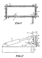
- a plastic stretching machine shown in plan view in Figure 1 is intended for use with a rectangular sheet of plastic material or any other vacuum formable material.
- Elongate clamping means are provided in the form of four clamping bars (1 to 4), one to clamp each edge of the rectangular plastic sheet.
- Clamping bars 1 and 3 oppose each other, as do clamping bars 2 and 4.
- Clamping bars 1 and 2 are fixed in place, whereas clamping bars 3 and 4 may be moved, as controlled by a programmable logic controller.
- Each clamping bar 1, 2, 3 and 4 comprises a plurality of secondary clamping means 5 (only some of which are labelled in Figure 1). These clamping means are mounted upon each clamp bar and may move along its length with a low co-efficient of friction.
- a rectangular hot thermoplastic sheet is placed within the device and is clamped around its four edges by the secondary clamps 5.
- This apparatus is shown in cross-section along line AA in Figure 2.
- the machine may also have means to itself heat the sheet and/or keep the sheet hot.
- Actuator 6 activates the clamping mechanism. This causes the clamping head to be rotated around joint 7 on support assembly 8 and the plastic sheet is held in the secondary clamps 5 between plates 9 and 10. Alternate pairs of clamp bars are then pulled apart. For example, whilst clamp bar 1 is held in place, clamp bar 3 may be moved away from it, stretching the plastic sheet in the longitudinal direction. Clamp bars 2 and 4 do not move. However, the secondary clamps 5 are free to move along the clamp bars. They are pulled along by the material sheet and therefore move proportionately to the movement of clamp bar 3. They act to resist scalloping of the plastic sheet.
- clamp bar 4 can be moved away from clamp bar 2, whilst clamp bar 1 and clamp bar 3 remain in place. Again, the clamping means move proportionately to the stretching of the sheet cause by movement in clamping bar 4 and prevent scalloping. In order for this to work there has to be very low friction preventing the movement of the secondary clamping means.
- an actuator 11 acting through a thrust pin 12 engages a primary clamping means which is provided on each clamped set and comprises a top plate 13 and bottom plate 14 within which the plastic sheet is securely held. All four sides are held at once.
- a mould is then driven up through the clamped sheet forming a seal.
- the mould is then vacuumed by conventional means to form the resulting mould.
- the secondary clamp carriages 5 are returned to their initial positions by the action of the primary clamp bars. A series of linkages prevent the secondary clamps 5 from getting too close to each other.
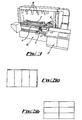
- FIG 4 shows a perspective view of the combined stretching and vacuum forming machine.
- conventional vacuum forming apparatus 15 is provided underneath the stretching apparatus.
- the machine also provides zoned cooling for control of thickness distribution in the final product. This is a technique used in the prior art and cooling apparatus 16 is mounted above the stretching apparatus.
- An electronic controller 17 is provided to allow automation of the procedure.
- Figure 4 shows a table of results from a Notched Charpy Impact Strength (N.C.I.S.) test performed to BS EN ISO 179/1eA - 1997 on samples of 5mm Acrylate Capped ABS taken through the above process.
- N.C.I.S. Notched Charpy Impact Strength
- Figure 5 (a) shows a conventional method for cutting up a sheet of plastic that is 3100mm x 1800mm to form four rectangular pieces 1750mm x 750mm for use in making a product sized 1700mm x 700mm. Note that offcuts are left around the edge.
- Figure 5 (b) shows how this same sheet can be cut into six rectangular pieces 1550mm x 600mm without offcuts, that may be stretched then used to give a product sized 1700mm x 700mm as before.
Landscapes
- Engineering & Computer Science (AREA)
- Mechanical Engineering (AREA)
- Blow-Moulding Or Thermoforming Of Plastics Or The Like (AREA)
- Shaping By String And By Release Of Stress In Plastics And The Like (AREA)
Abstract
Description
Claims (14)
- A machine for stretching and vacuum forming a rectangular sheet of plastic material, the machine having a first and second orthogonal pairs of opposed elongate clamping means (1-4) which engagably co-operate with the sides of said sheet and thereby hold said sheet, wherein the elongate clamping means (1-4) comprise primary clamping means (13,14) and secondary (5) clamping means, with the primary clamping means (13,14) engageably and fixedly clamping a side of the sheet of the plastic material and the secondary clamping means (5) engageably clamping a portion of the edge of the rectangular sheet of plastic and being adapted to move along the length of the elongate clamping means (1-4), the machine including a means to controllably urge apart a first pair of opposed elongate clamping means (1 and 3) and thereby stretch a sheet held therebetween, whereby the second pair of opposed elongate clamping means (2 and 4) uses the movable secondary clamping means (5) to allow said sheet to stretch uniformly in a direction parallel to the lengths of the second pair of elongate clamping means (2 and 4) whilst resisting movement of the clamped sides of the sheet in a direction orthogonal to the lengths of the second pair of elongate clamping means (2 and 4), and once the plastic sheet has been stretched the fixed primary clamping means (13,14) are then used to hold the plastic sheet in a fixed position during the vacuum forming process.
- A machine for stretching and vacuum forming a rectangular sheet of plastic material as Claimed in Claim 1, the machine including means to controllably urge apart both pairs of opposed elongate clamping means (1-4) and thereby stretch a sheet held therein in two dimensions, each elongate clamping means (1-4) using the secondary clamping means (5) to allow said sheet to stretch uniformly in a direction parallel to the length of said individual elongate clamping means (1-4) whilst resisting movement of the side of the rectangular sheet clamped by said individual elongate clamping means (1-4) in a direction orthogonal to the length of said individual elongate clamping means(1-4).
- A machine for stretching and vacuum forming a rectangular sheet of plastic material as Claimed in Claim 1 or Claim 2, the machine being adapted to stretch the sheet first in one direction and then subsequently in a second direction orthogonal to the first direction.
- A machine for stretching and vacuum forming a rectangular sheet of plastic as claimed in any of the previous Claims, wherein the secondary clamps are moved along the length of the elongate clamping means by the motion of the sheet.
- A machine for stretching and vacuum forming a rectangular sheet of plastic as claimed in any preceding Claim, the machine having a heating means for evenly heating a plastic sheet held therein.
- A machine for stretching and vacuum forming a rectangular sheet of plastic as claimed in any preceding Claim, wherein the vacuum forming means is engagable and adapted to vacuum form a rectangular sheet of plastic stretched by the machine for stretching a rectangular sheet of plastic whilst said rectangular sheet of plastic is still held within the elongate clamping means (1-4) of the machine by the primary fixed clamping means (13,14).
- A machine for stretching and vacuum forming a rectangular sheet of plastic as claimed in any preceding Claim, the machine having a means for selectively cooling zones of the plastic sheet held therein.
- A method of stretching and vacuum forming a rectangular sheet of plastic material, the method comprising the steps of:(a) engagably holding the sides of said sheet using movable clamping means (5); and(b)(i) stretching said sheet along a first axis of said sheet whilst holding the sides of said sheet parallel to the first axis so as to allow the sheet to stretch proportionately along the first axis but so as to resist deformation of the sides of said sheet orthogonal to the first axis; and(c) fixedly holding the sides of said stretched sheet using fixed clamping means (13,14); and(d) vacuum forming said streched sheet.
- A method of stretching and vacuum forming a rectangular sheet of plastic material as claimed in Claim 8, the method further having the step of:(b)(ii) stretching said sheet along a second axis of said sheet whilst holding the sides of said sheet parallel to the second axis so as to allow the sheet to stretch proportionately along the second axis but so as to resist deformation of the sides of said sheet orthogonal to the second axis, the second axis being orthogonal to the first axis.
- A method of stretching and vacuum forming a rectangular sheet of plastic material as claimed in Claim 8, the method involving, simultaneous to stretching said sheet parallel to a first axis, also stretching said sheet along a second axis of said sheet whilst holding the sides of said sheet parallel to the second axis so as to allow the sheet to stretch proportionately along the second axis but so as to resist deformation of the sides of said sheet orthogonal to the second axis, the second axis being orthogonal to the first axis.
- A method of stretching and vacuum forming a rectangular sheet of plastic material as claimed in Claim 8 wherein the secondary clamps are adapted to move along the length of the elongate clamping means (1-4) proportionately to the stretching of the sheet along an axis parallel to the clamping means.
- A method of stretching and vacuum forming a rectangular sheet of plastic material as claimed in Claim 11 wherein the secondary clamps are moved along the length of the elongate clamping (1-4) means by the motion of the sheet.
- A method of stretching and vacuum forming a rectangular sheet of plastic material as claimed in any of Claims 8 to 12, the method having the step of heating the sheet of plastic material.
- A method of stretching and vacuum forming a rectangular sheet of plastic material as claimed in Claim 8 or Claim 13 wherein zones of the plastic material are selectively cooled.
Applications Claiming Priority (5)
| Application Number | Priority Date | Filing Date | Title |
|---|---|---|---|
| GB9828820 | 1998-12-31 | ||
| GBGB9828820.2A GB9828820D0 (en) | 1998-12-31 | 1998-12-31 | In process method for controlled strectching op rectangular vacuum formable sheet material |
| GBGB9925486.4A GB9925486D0 (en) | 1999-10-28 | 1999-10-28 | Plastic stretching method and apparatus for use in vacuum forming techniques |
| GB9925486 | 1999-10-28 | ||
| PCT/GB1999/004391 WO2000040392A1 (en) | 1998-12-31 | 1999-12-30 | Plastic stretching method and apparatus for use in vacuum forming techniques |
Publications (2)
| Publication Number | Publication Date |
|---|---|
| EP1140470A1 EP1140470A1 (en) | 2001-10-10 |
| EP1140470B1 true EP1140470B1 (en) | 2003-07-23 |
Family
ID=26314941
Family Applications (1)
| Application Number | Title | Priority Date | Filing Date |
|---|---|---|---|
| EP99963637A Expired - Lifetime EP1140470B1 (en) | 1998-12-31 | 1999-12-30 | Plastic stretching method and apparatus for use in vacuum forming techniques |
Country Status (5)
| Country | Link |
|---|---|
| EP (1) | EP1140470B1 (en) |
| AT (1) | ATE245521T1 (en) |
| AU (1) | AU1987900A (en) |
| DE (1) | DE69909835T2 (en) |
| WO (1) | WO2000040392A1 (en) |
Cited By (2)
| Publication number | Priority date | Publication date | Assignee | Title |
|---|---|---|---|---|
| DE102011101231A1 (en) | 2010-06-15 | 2011-12-15 | Kiefel Gmbh | Method and apparatus for stretching and forming a film blank and product made therewith |
| WO2011045600A3 (en) * | 2009-10-12 | 2012-05-31 | Stretchform Associates Limited | Clamping apparatus |
Families Citing this family (8)
| Publication number | Priority date | Publication date | Assignee | Title |
|---|---|---|---|---|
| GB2474366B (en) * | 2009-10-12 | 2012-11-14 | Stretchform Associates Ltd | Zone cooling |
| JP5617796B2 (en) * | 2011-08-10 | 2014-11-05 | トヨタ車体株式会社 | Vacuum forming method for interior parts and vacuum forming apparatus for interior parts |
| CN103331907B (en) * | 2013-06-03 | 2016-08-10 | 南京航空航天大学 | A kind of preparation facilities of carbon nanotube resin film and preparation method thereof |
| US10106226B2 (en) | 2015-07-29 | 2018-10-23 | Free Form Factory Inc. | Personal watercraft chassis |
| US10391702B2 (en) | 2015-11-24 | 2019-08-27 | Free Form Factory, Inc. | Personal watercraft fabrication using thermoforming |
| DE102016012425A1 (en) | 2016-06-12 | 2017-09-07 | Kiefel Gmbh | Device and method for stretching and / or forming and / or laminating placing a film element and laminating station and installation for laminating a component |
| DE102019000300A1 (en) | 2018-09-19 | 2020-03-19 | Kiefel Gmbh | GRIPPER FOR A DEVICE FOR MOLDING AND / OR LAMINATING A FILM ELEMENT, DRAPING FRAME, DEVICE FOR MOLDING AND / OR LAMINATING A FILM ELEMENT, PLANT FOR PRODUCING A MOLDED PART OR A LAMINATED COMPONENT, METHOD FOR MOLDING OR FABRICATING FORMING |
| US12157266B2 (en) | 2021-11-03 | 2024-12-03 | Dräxlmaier Group | Gripper for a draping frame and for a device, draping frame, device and method for the forming of and/or covering using a film element, system for manufacturing a moulded part or a covered component, method for retro-fitting a device of this type, method for manufacturing a covered component |
Family Cites Families (6)
| Publication number | Priority date | Publication date | Assignee | Title |
|---|---|---|---|---|
| US3579718A (en) * | 1968-10-17 | 1971-05-25 | Sierracin Corp | Apparatus for stretching sheet material |
| US3635640A (en) * | 1968-10-17 | 1972-01-18 | Sierracin Corp | Apparatus for stretching sheet material |
| SU706249A1 (en) * | 1978-07-31 | 1979-12-30 | Предприятие П/Я Р-6115 | Machine for drawing thermoplastic sheets |
| JPS6049921A (en) * | 1983-08-30 | 1985-03-19 | Toyota Motor Corp | Vacuum molding of synthetic resin |
| JPS63197626A (en) * | 1987-02-12 | 1988-08-16 | Sintokogio Ltd | Method for molding resin product |
| DE4314641C5 (en) * | 1993-05-04 | 2007-07-26 | Geiss Ag | Clamping frame for thermoforming machines |
-
1999
- 1999-12-30 WO PCT/GB1999/004391 patent/WO2000040392A1/en not_active Ceased
- 1999-12-30 AU AU19879/00A patent/AU1987900A/en not_active Abandoned
- 1999-12-30 DE DE69909835T patent/DE69909835T2/en not_active Expired - Lifetime
- 1999-12-30 EP EP99963637A patent/EP1140470B1/en not_active Expired - Lifetime
- 1999-12-30 AT AT99963637T patent/ATE245521T1/en not_active IP Right Cessation
Cited By (3)
| Publication number | Priority date | Publication date | Assignee | Title |
|---|---|---|---|---|
| WO2011045600A3 (en) * | 2009-10-12 | 2012-05-31 | Stretchform Associates Limited | Clamping apparatus |
| DE102011101231A1 (en) | 2010-06-15 | 2011-12-15 | Kiefel Gmbh | Method and apparatus for stretching and forming a film blank and product made therewith |
| EP2397308A2 (en) | 2010-06-15 | 2011-12-21 | KIEFEL GmbH | Method and device for stretching and forming a film blank and product produced using same |
Also Published As
| Publication number | Publication date |
|---|---|
| DE69909835T2 (en) | 2004-04-22 |
| AU1987900A (en) | 2000-07-24 |
| EP1140470A1 (en) | 2001-10-10 |
| ATE245521T1 (en) | 2003-08-15 |
| DE69909835D1 (en) | 2003-08-28 |
| WO2000040392A1 (en) | 2000-07-13 |
Similar Documents
| Publication | Publication Date | Title |
|---|---|---|
| US5863568A (en) | Method and apparatus for thermoforming thermoplastic sheets | |
| EP1140470A1 (en) | Plastic stretching method and apparatus for use in vacuum forming techniques | |
| US6659758B2 (en) | System for twin sheet forming | |
| CA1204996A (en) | Process for thermoforming reinforced polymer sheets | |
| KR101641751B1 (en) | Device for stretching film sections in a monoaxial or biaxial manner | |
| CN106040906B (en) | Method for automatically bending spacer elements and machine for carrying out said method | |
| AU2011261805B2 (en) | Apparatus and methods for selective thermoforming | |
| DE19515192A1 (en) | Film-protective simultaneous injection-moulding/painting | |
| GB2494075A (en) | Method of manufacturing a compound multiple curved surface molding plate | |
| RU2004115754A (en) | METHODS AND SYSTEMS FOR PROCESSING SUBSTRATES USING DYNAMIC LIQUID MENISKS | |
| CA2620017A1 (en) | Twin-sheet thermoforming process and apparatus for insert inclusion | |
| EP2875931B1 (en) | Method for forming a sheet of reinforced thermoplastic material | |
| US5385465A (en) | Verticle thermoforming apparatus | |
| US4847034A (en) | Vacuum forming method | |
| US4516997A (en) | Method of and apparatus for vacuum shaping a glass sheet | |
| CA1260218A (en) | Heating apparatus for heating sheet material before the forming process | |
| WO1996005922A1 (en) | Method and device for the deformation of plate material | |
| JPH04265729A (en) | Thermoforming method of polycarbonate resin sheet | |
| CN223314442U (en) | Sheet preheating and heating mechanism of thermoforming machine | |
| EP0670214B1 (en) | Vertical thermoforming apparatus | |
| JPH1058536A (en) | Thermoforming equipment for thermoplastic resin sheets | |
| JP3839156B2 (en) | Substrate / sheet integrated molding method | |
| CA2530022C (en) | Deep-drawing machine for producing deep-drawn objects, containers, packaging or similar and method for producing objects of this type | |
| WO2011045599A2 (en) | Zone cooling | |
| WO2011045600A2 (en) | Clamping apparatus |
Legal Events
| Date | Code | Title | Description |
|---|---|---|---|
| PUAI | Public reference made under article 153(3) epc to a published international application that has entered the european phase |
Free format text: ORIGINAL CODE: 0009012 |
|
| 17P | Request for examination filed |
Effective date: 20010723 |
|
| AK | Designated contracting states |
Kind code of ref document: A1 Designated state(s): AT BE CH CY DE DK ES FI FR GB GR IE IT LI LU MC NL PT SE |
|
| GRAH | Despatch of communication of intention to grant a patent |
Free format text: ORIGINAL CODE: EPIDOS IGRA |
|
| GRAH | Despatch of communication of intention to grant a patent |
Free format text: ORIGINAL CODE: EPIDOS IGRA |
|
| GRAA | (expected) grant |
Free format text: ORIGINAL CODE: 0009210 |
|
| RAP1 | Party data changed (applicant data changed or rights of an application transferred) |
Owner name: PRESTON ASSOCIATES (EUROPE) LDA |
|
| AK | Designated contracting states |
Designated state(s): AT BE CH CY DE DK ES FI FR GB GR IE IT LI LU MC NL PT SE |
|
| PG25 | Lapsed in a contracting state [announced via postgrant information from national office to epo] |
Ref country code: NL Free format text: LAPSE BECAUSE OF FAILURE TO SUBMIT A TRANSLATION OF THE DESCRIPTION OR TO PAY THE FEE WITHIN THE PRESCRIBED TIME-LIMIT Effective date: 20030723 Ref country code: LI Free format text: LAPSE BECAUSE OF FAILURE TO SUBMIT A TRANSLATION OF THE DESCRIPTION OR TO PAY THE FEE WITHIN THE PRESCRIBED TIME-LIMIT Effective date: 20030723 Ref country code: FI Free format text: LAPSE BECAUSE OF FAILURE TO SUBMIT A TRANSLATION OF THE DESCRIPTION OR TO PAY THE FEE WITHIN THE PRESCRIBED TIME-LIMIT Effective date: 20030723 Ref country code: CH Free format text: LAPSE BECAUSE OF FAILURE TO SUBMIT A TRANSLATION OF THE DESCRIPTION OR TO PAY THE FEE WITHIN THE PRESCRIBED TIME-LIMIT Effective date: 20030723 Ref country code: BE Free format text: LAPSE BECAUSE OF FAILURE TO SUBMIT A TRANSLATION OF THE DESCRIPTION OR TO PAY THE FEE WITHIN THE PRESCRIBED TIME-LIMIT Effective date: 20030723 Ref country code: AT Free format text: LAPSE BECAUSE OF FAILURE TO SUBMIT A TRANSLATION OF THE DESCRIPTION OR TO PAY THE FEE WITHIN THE PRESCRIBED TIME-LIMIT Effective date: 20030723 |
|
| REG | Reference to a national code |
Ref country code: GB Ref legal event code: FG4D |
|
| REG | Reference to a national code |
Ref country code: CH Ref legal event code: EP |
|
| REG | Reference to a national code |
Ref country code: IE Ref legal event code: FG4D |
|
| REF | Corresponds to: |
Ref document number: 69909835 Country of ref document: DE Date of ref document: 20030828 Kind code of ref document: P |
|
| PG25 | Lapsed in a contracting state [announced via postgrant information from national office to epo] |
Ref country code: SE Free format text: LAPSE BECAUSE OF FAILURE TO SUBMIT A TRANSLATION OF THE DESCRIPTION OR TO PAY THE FEE WITHIN THE PRESCRIBED TIME-LIMIT Effective date: 20031023 Ref country code: GR Free format text: LAPSE BECAUSE OF FAILURE TO SUBMIT A TRANSLATION OF THE DESCRIPTION OR TO PAY THE FEE WITHIN THE PRESCRIBED TIME-LIMIT Effective date: 20031023 Ref country code: DK Free format text: LAPSE BECAUSE OF FAILURE TO SUBMIT A TRANSLATION OF THE DESCRIPTION OR TO PAY THE FEE WITHIN THE PRESCRIBED TIME-LIMIT Effective date: 20031023 |
|
| PG25 | Lapsed in a contracting state [announced via postgrant information from national office to epo] |
Ref country code: ES Free format text: LAPSE BECAUSE OF FAILURE TO SUBMIT A TRANSLATION OF THE DESCRIPTION OR TO PAY THE FEE WITHIN THE PRESCRIBED TIME-LIMIT Effective date: 20031103 |
|
| NLV1 | Nl: lapsed or annulled due to failure to fulfill the requirements of art. 29p and 29m of the patents act | ||
| PG25 | Lapsed in a contracting state [announced via postgrant information from national office to epo] |
Ref country code: PT Free format text: LAPSE BECAUSE OF FAILURE TO SUBMIT A TRANSLATION OF THE DESCRIPTION OR TO PAY THE FEE WITHIN THE PRESCRIBED TIME-LIMIT Effective date: 20031223 |
|
| PG25 | Lapsed in a contracting state [announced via postgrant information from national office to epo] |
Ref country code: LU Free format text: LAPSE BECAUSE OF NON-PAYMENT OF DUE FEES Effective date: 20031230 Ref country code: IE Free format text: LAPSE BECAUSE OF NON-PAYMENT OF DUE FEES Effective date: 20031230 Ref country code: CY Free format text: LAPSE BECAUSE OF FAILURE TO SUBMIT A TRANSLATION OF THE DESCRIPTION OR TO PAY THE FEE WITHIN THE PRESCRIBED TIME-LIMIT Effective date: 20031230 |
|
| PG25 | Lapsed in a contracting state [announced via postgrant information from national office to epo] |
Ref country code: MC Free format text: LAPSE BECAUSE OF NON-PAYMENT OF DUE FEES Effective date: 20031231 |
|
| REG | Reference to a national code |
Ref country code: CH Ref legal event code: PL |
|
| ET | Fr: translation filed | ||
| PLBE | No opposition filed within time limit |
Free format text: ORIGINAL CODE: 0009261 |
|
| STAA | Information on the status of an ep patent application or granted ep patent |
Free format text: STATUS: NO OPPOSITION FILED WITHIN TIME LIMIT |
|
| 26N | No opposition filed |
Effective date: 20040426 |
|
| REG | Reference to a national code |
Ref country code: IE Ref legal event code: MM4A |
|
| REG | Reference to a national code |
Ref country code: FR Ref legal event code: TP |
|
| REG | Reference to a national code |
Ref country code: GB Ref legal event code: 732E |
|
| PGFP | Annual fee paid to national office [announced via postgrant information from national office to epo] |
Ref country code: GB Payment date: 20121219 Year of fee payment: 14 Ref country code: IT Payment date: 20121218 Year of fee payment: 14 |
|
| PGFP | Annual fee paid to national office [announced via postgrant information from national office to epo] |
Ref country code: FR Payment date: 20130107 Year of fee payment: 14 |
|
| PGFP | Annual fee paid to national office [announced via postgrant information from national office to epo] |
Ref country code: DE Payment date: 20121220 Year of fee payment: 14 |
|
| REG | Reference to a national code |
Ref country code: DE Ref legal event code: R119 Ref document number: 69909835 Country of ref document: DE |
|
| GBPC | Gb: european patent ceased through non-payment of renewal fee |
Effective date: 20131230 |
|
| REG | Reference to a national code |
Ref country code: DE Ref legal event code: R119 Ref document number: 69909835 Country of ref document: DE Effective date: 20140701 |
|
| REG | Reference to a national code |
Ref country code: FR Ref legal event code: ST Effective date: 20140829 |
|
| PG25 | Lapsed in a contracting state [announced via postgrant information from national office to epo] |
Ref country code: DE Free format text: LAPSE BECAUSE OF NON-PAYMENT OF DUE FEES Effective date: 20140701 |
|
| PG25 | Lapsed in a contracting state [announced via postgrant information from national office to epo] |
Ref country code: GB Free format text: LAPSE BECAUSE OF NON-PAYMENT OF DUE FEES Effective date: 20131230 Ref country code: FR Free format text: LAPSE BECAUSE OF NON-PAYMENT OF DUE FEES Effective date: 20131231 |
|
| PG25 | Lapsed in a contracting state [announced via postgrant information from national office to epo] |
Ref country code: IT Free format text: LAPSE BECAUSE OF NON-PAYMENT OF DUE FEES Effective date: 20131231 |
|
| PG25 | Lapsed in a contracting state [announced via postgrant information from national office to epo] |
Ref country code: IT Free format text: LAPSE BECAUSE OF NON-PAYMENT OF DUE FEES Effective date: 20131230 |