EP1142042B1 - Vorrichtung zum elektrolytbefüllen der zellen eines akkumulators - Google Patents
Vorrichtung zum elektrolytbefüllen der zellen eines akkumulators Download PDFInfo
- Publication number
- EP1142042B1 EP1142042B1 EP00960481A EP00960481A EP1142042B1 EP 1142042 B1 EP1142042 B1 EP 1142042B1 EP 00960481 A EP00960481 A EP 00960481A EP 00960481 A EP00960481 A EP 00960481A EP 1142042 B1 EP1142042 B1 EP 1142042B1
- Authority
- EP
- European Patent Office
- Prior art keywords
- filling
- electrolyte
- receptacle
- battery
- cell
- Prior art date
- Legal status (The legal status is an assumption and is not a legal conclusion. Google has not performed a legal analysis and makes no representation as to the accuracy of the status listed.)
- Expired - Lifetime
Links
- 239000003792 electrolyte Substances 0.000 title claims abstract description 37
- 239000000945 filler Substances 0.000 abstract description 4
- 238000005429 filling process Methods 0.000 description 8
- WHXSMMKQMYFTQS-UHFFFAOYSA-N Lithium Chemical compound [Li] WHXSMMKQMYFTQS-UHFFFAOYSA-N 0.000 description 6
- 229910052744 lithium Inorganic materials 0.000 description 6
- 238000000034 method Methods 0.000 description 2
- 238000007789 sealing Methods 0.000 description 2
- 238000009423 ventilation Methods 0.000 description 2
- XLYOFNOQVPJJNP-UHFFFAOYSA-N water Substances O XLYOFNOQVPJJNP-UHFFFAOYSA-N 0.000 description 2
- 208000033999 Device damage Diseases 0.000 description 1
- 239000002253 acid Substances 0.000 description 1
- 238000009835 boiling Methods 0.000 description 1
- 238000001514 detection method Methods 0.000 description 1
- 230000000694 effects Effects 0.000 description 1
- 239000011245 gel electrolyte Substances 0.000 description 1
- 239000011244 liquid electrolyte Substances 0.000 description 1
- 239000000565 sealant Substances 0.000 description 1
- 238000011144 upstream manufacturing Methods 0.000 description 1
Images
Classifications
-
- H—ELECTRICITY
- H01—ELECTRIC ELEMENTS
- H01M—PROCESSES OR MEANS, e.g. BATTERIES, FOR THE DIRECT CONVERSION OF CHEMICAL ENERGY INTO ELECTRICAL ENERGY
- H01M50/00—Constructional details or processes of manufacture of the non-active parts of electrochemical cells other than fuel cells, e.g. hybrid cells
- H01M50/60—Arrangements or processes for filling or topping-up with liquids; Arrangements or processes for draining liquids from casings
- H01M50/609—Arrangements or processes for filling with liquid, e.g. electrolytes
- H01M50/618—Pressure control
-
- H—ELECTRICITY
- H01—ELECTRIC ELEMENTS
- H01M—PROCESSES OR MEANS, e.g. BATTERIES, FOR THE DIRECT CONVERSION OF CHEMICAL ENERGY INTO ELECTRICAL ENERGY
- H01M50/00—Constructional details or processes of manufacture of the non-active parts of electrochemical cells other than fuel cells, e.g. hybrid cells
- H01M50/60—Arrangements or processes for filling or topping-up with liquids; Arrangements or processes for draining liquids from casings
- H01M50/609—Arrangements or processes for filling with liquid, e.g. electrolytes
- H01M50/627—Filling ports
-
- Y—GENERAL TAGGING OF NEW TECHNOLOGICAL DEVELOPMENTS; GENERAL TAGGING OF CROSS-SECTIONAL TECHNOLOGIES SPANNING OVER SEVERAL SECTIONS OF THE IPC; TECHNICAL SUBJECTS COVERED BY FORMER USPC CROSS-REFERENCE ART COLLECTIONS [XRACs] AND DIGESTS
- Y02—TECHNOLOGIES OR APPLICATIONS FOR MITIGATION OR ADAPTATION AGAINST CLIMATE CHANGE
- Y02E—REDUCTION OF GREENHOUSE GAS [GHG] EMISSIONS, RELATED TO ENERGY GENERATION, TRANSMISSION OR DISTRIBUTION
- Y02E60/00—Enabling technologies; Technologies with a potential or indirect contribution to GHG emissions mitigation
- Y02E60/10—Energy storage using batteries
Definitions
- the invention relates to a device for electrolyte filling at least one cell of a rechargeable battery, with one Vacuum pump for evacuating the cell of the accumulator and with a filling device for introducing the electrolyte into a Filling opening of a cell and with a recipient for Recording of the entire accumulator, whereby the recipient over a terminal is connected to the vacuum pump, so that the Accumulator as a whole can be placed under vacuum and the filling device at least one supply line for the Electrolyte, the vacuum-tight in the recipient is led into it.
- the inserts due to the evacuation of only single cells of the accumulator the inserts, For example, the lead plates, strongly pressed together or - are pressed so that with this conventional device Damage to the separator can not be excluded can.
- a major problem is that it often due to the deformation of the entire accumulator is not possible, the required volume of electrolyte in to introduce the individual cells.
- the known device is further formed mechanically very expensive. The Fill opening of each cell is to be sealed individually. The same applies to the ventilation holes.
- the device has a Recipients in which one or more lithium cells for Filling with electrolyte can be arranged. It will be the lithium cells with their single filling opening down pointing to a stand inside the recipient positioned. Subsequently, the recipient is evacuated to Remove water and water vapor from the cells. thereupon the negative pressure is reduced, so that this above the Boiling point of the liquid electrolyte to be filled is. Thereafter, the recipient is filled with electrolyte, wherein the Inlet openings of the lithium cells in the electrolyte plunge.
- the negative pressure in the Recipient to atmospheric pressure and then to one Overpressure increased so that the electrolyte through the Inlet opening can penetrate into the lithium cell. After filling the inlet opening is hermetically sealed, and the Lithium cell is ready for use.
- DE 39 12 846 C1 discloses a method for Filling electrochemical cells, in particular High power cells, such as lithium cells, with an electrolyte known, the cell initially evacuated and thereby simultaneously checked for short circuit and at Detecting a short circuit the further filling process is canceled. After reaching the final vacuum, the cell then filled with the electrolyte and at the same time monitors the electrical voltage applied to the cell, wherein upon detection of a voltage deviation of the Filling process is canceled.
- the present invention has the object based, a device of the type mentioned develop further to the effect that while avoiding aforementioned disadvantages a simple and rapid evacuation and filling the cells of the accumulator with electrolyte is possible.
- the achievable with the device according to the invention advantages are that due to the application of the vacuum to the entire accumulator this exposed to any stress is and therefore no deformation on the accumulator housing occur.
- the entire space of the cells stands or filling openings for filling with electrolyte for Available.
- the filling process can thus be carried out faster and the filling quantity can be optimized.
- can be in the Recipients also have a higher vacuum than conventional ones Reach device because the recipient is extremely vacuum-tight can be executed. Also eliminates the high cost of the Sealing the filling openings for the individual cells as well the ventilation holes. It is only necessary to that the recipient is self-sealed.
- the supply lines Of particular advantage each end a filling head with an outlet on. This engages the outlet with Insert into the filling openings of the cells of the accumulator, so that the individual cells already with the in the Gukopf located filling head or Outlet first evacuated and then with electrolyte can be filled.
- the recipient can vacuum-tight on a the accumulator bearing base plate are discontinued.
- a structurally simple sealing surface between Recipient and bottom plate created so that with relative simple sealants a high vacuum within the Recipients can be maintained.
- a lifting device assigned, by means of which the recipient of the bottom plate can be raised or lowered.
- the accumulator of the Base plate removed and through a new, to be filled Replace accumulator.
- the recipient is using the Lifting device first raised and after replacing the Batteries lowered back to the bottom plate, which the recipient then vacuum-tight.
- the recipient points to another Embodiment of the invention a the accumulator in essentially adapted form and is essentially as cuboid housing formed, which only slightly larger than the accumulator itself is.
- the Dimensions is only to ensure that the Supply lines for the electrolyte sufficient space in the Recipients have.
- the recipient to be as small as possible in terms of volume content, ensures that not unnecessarily much air to produce the Vacuum must be pumped in the cells of the accumulator, whereby the duration of the filling process continues is reduced.
- the supply lines or the filling heads in the housing of the recipient preferably on rods or the like holding means attached.
- the Arrangement of the supply lines or filling heads in Housing of the recipient such that when lowering the Recipients on the bottom plate the supply lines or filling heads in the filling openings of the cells drive in automatically and on the bottom plate seated recipient with play in the filler openings are included.
- a vacuum in the recipient After completion of the lowering process is then by means of the vacuum pump, a vacuum in the recipient and thus also generated in the cells of the accumulator.
- connection for the vacuum device edge the recipient in a corner away the Einglallö Anlagenen of the accumulator or the Filling heads arranged. Because of this measure is the Connection for the vacuum pump as far away as possible Filling openings or filling heads arranged so that the risk of electrolyte entering the outlet for the vacuum pump is effectively counteracted.
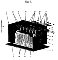
- a device 10 for electrolyte filling the cells of an accumulator 12 are shown.
- To evacuate the cells of the accumulator 12 is a symbolic with the Reference numeral 14 designated vacuum pump provided.
- the device 10 has a filling device 16 for Introduction of the electrolyte into the cells of the accumulator 12 on.
- the accumulator 12 is completely in a recipient 18th taken, wherein the recipient 18 via a terminal 20 with the vacuum pump 14 is connected. This makes it possible that the accumulator 12 as a whole be placed under vacuum can.
- the filling device 16 has at least one, preferably a plurality of supply lines 22 for the electrolyte, wherein the Supply lines 22 vacuum-tight in the recipient 18th are led into it.
- the recipient 18 vacuum-tight on a battery 12 carrying the bottom plate 24 discontinued. Furthermore, the recipient 18 is a Lifting device 26, which is symbolically represented by arrows is assigned, with which the recipient 18 is raised or is lowered.
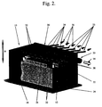
- the recipient 18 a the Accumulator 12 substantially adapted shape and is total as a substantially cuboid, down open housing 28 formed in the lowered Position sealed according to Figure 2 by the bottom plate 24 becomes.
- the supply lines 22 are through a housing wall 30th of the recipient 18 towards filling openings 32 of the cells of the Accumulator 12 out.
- the supply lines 22 have each end a filling head 34 with an outlet 36.
- the outlet port 36 is in the lowered position of the Recipients 18 recorded with game in the filling opening 32.
- connection 20 for the vacuum pump 14 is the edge of the Recipient 18 in a corner area removes the Fill openings 32 arranged.
Landscapes
- Chemical & Material Sciences (AREA)
- Chemical Kinetics & Catalysis (AREA)
- Electrochemistry (AREA)
- General Chemical & Material Sciences (AREA)
- Filling, Topping-Up Batteries (AREA)
- Secondary Cells (AREA)
- Supplying Of Containers To The Packaging Station (AREA)
- Immobilizing And Processing Of Enzymes And Microorganisms (AREA)
Description
- Figur 1
- ein Ausführungsbeispiel der erfindungsgemäßen Vorrichtung in perspektivischer Ansicht, mit teilweise weggebrochenem Rezipientengehäuse und in angehobener Stellung des Rezipienten und
- Figur 2
- die Vorrichtung gemäß Figur 1, wobei der Rezipient auf die Bodenplatte abgesenkt ist.
- 10 -
- Vorrichtung
- 12 -
- Akkumulator
- 14 -
- Vakuumpumpe
- 16 -
- Fülleinrichtung
- 18 -
- Rezipient
- 20 -
- Anschluß
- 22 -
- Zufuhrleitung
- 24 -
- Bodenplatte
- 26 -
- Hubvorrichtung
- 28 -
- Gehäuse
- 30 -
- Gehäusewand
- 32 -
- Einfüllöffnung
- 34 -
- Füllkopf
- 36 -
- Auslaßstutzen
- 38 -
- Stange
Claims (10)
- Vorrichtung (10) zum Elektrolytbefüllen wenigstens einer Zelle eines Akkumulators (12), mit einer Vakuumpumpe (14) zum Evakuieren der Zelle des Akkumulators (12) und mit einer Fülleinrichtung (16) zum Einbringen des Elektrolyts in eine Einfüllöffnung (32) einer Zelle und mit einem Rezipienten (18) zur Aufnahme des gesamten Akkumulators (12), wobei der Rezipient (18) über einen Anschluß (20) mit der Vakuumpumpe (14) verbunden ist, so daß der Akkumulator (12) als Ganzes unter Vakuum gesetzt werden kann und die Fülleinrichtung (16) wenigstens eine Zufuhrleitung (22) für den Elektrolyt aufweist, die vakuumdicht in den Rezipienten (18) hineingeführt ist, dadurch gekennzeichnet, daß die Zufuhrleitung (22) endseitig jeweils einen Füllkopf (34) mit einem Auslaßstutzen (36) aufweist und der Auslaßstutzen (36) mit Spiel in die Einfüllöffnung (32) einer Zelle greift, so dass die einzelnen Zellen bereits mit dem in der Füllposition befindlichen Füllkopf beziehungsweise Auslaßstutzen zunächst evakuiert und dann mit Elektrolyt befüllt werden können.
- Vorrichtung nach Anspruch 1, dadurch gekennzeichnet, daß der Rezipient (18) vakuumdicht auf eine den Akkumulator (12) tragende Bodenplatte (24) abgesetzt werden kann.
- Vorrichtung nach Anspruch 1 oder 2, dadurch gekennzeichnet, daß der Rezipient (18) mittels einer zugeordneten Hubvorrichtung(26) angehoben und abgesenkt wird.
- Vorrichtung nach einem der vorhergehenden Ansprüche, dadurch gekennzeichnet, daß Rezipient (18) einer dem Akkumulator (12) im wesentlichen angepaßte Form aufweist und im wesentlichen als quaderförmiges, insbesondere nach unten geöffnetes Gehäuse (28) ausgebildet ist.
- Vorrichtung nach einem der vorhergehenden Ansprüche, dadurch gekennzeichnet, daß die eine oder mehrere Zufuhrleitungen (22) durch eine Gehäusewand (30) des Rezipienten (18) hin zu Einfüllöffnung (32) einer Zellen des Akkumulators (12) geführt sind.
- Vorrichtung nach einem der vorhergehenden Ansprüche, dadurch gekennzeichnet, daß der Akkumulator (12) mehrere Zellen mit jeweils einer Einfüllöffnung (32) aufweist, wobei jeder Einfüllöffnung (32) eine Zufuhrleitung (22) mit Füllkopf (34) und Auslaßstutzen (36) zugeordnet ist.
- Vorrichtung nach einem der vorhergehenden Ansprüche, dadurch gekennzeichnet, daß die Zufuhrleitungen (22) beziehungsweise die Füllköpfe (34) im Gehäuse (28) des Rezipienten (18), bevorzugt an Stangen (38) oder dergleichen Haltemitteln, befestigt sind.
- Vorrichtung nach einem der vorhergehenden Ansprüche, dadurch gekennzeichnet, daß die Füllköpfe (34) korrespondierend zur Anordnung der Einfüllöffnungen (32) des Akkumulators (12) am beziehungsweise im Rezipienten (18) befestigt sind.
- Vorrichtung nach einem der vorhergehenden Ansprüche, dadurch gekennzeichnet, daß die Füllköpfe (34) beziehungweise Zufuhrleitungen (22) an den Haltemitteln beziehungsweise Stangen (38) relativ zueinander verstellbar befestigt sind.
- Vorrichtung nach einem der vorhergehenden Ansprüche, dadurch gekennzeichnet, daß der Anschluß für die Vakuumeinrichtung randseitig des Rezipienten (18) in einem Eckbereich entfernt der Einfüllöffnungen (32) angeordnet ist.
Applications Claiming Priority (3)
| Application Number | Priority Date | Filing Date | Title |
|---|---|---|---|
| DE29915950U DE29915950U1 (de) | 1999-09-10 | 1999-09-10 | Vorrichtung zum Elektrolytbefüllen der Zellen eines Akkumulators |
| DE29915950U | 1999-09-10 | ||
| PCT/EP2000/008060 WO2001020694A1 (de) | 1999-09-10 | 2000-08-18 | Vorrichtung zum elektrolytbefüllen der zellen eines akkumulators |
Publications (2)
| Publication Number | Publication Date |
|---|---|
| EP1142042A1 EP1142042A1 (de) | 2001-10-10 |
| EP1142042B1 true EP1142042B1 (de) | 2005-07-27 |
Family
ID=8078748
Family Applications (1)
| Application Number | Title | Priority Date | Filing Date |
|---|---|---|---|
| EP00960481A Expired - Lifetime EP1142042B1 (de) | 1999-09-10 | 2000-08-18 | Vorrichtung zum elektrolytbefüllen der zellen eines akkumulators |
Country Status (7)
| Country | Link |
|---|---|
| US (1) | US6588460B1 (de) |
| EP (1) | EP1142042B1 (de) |
| JP (1) | JP4759704B2 (de) |
| AT (1) | ATE300789T1 (de) |
| DE (2) | DE29915950U1 (de) |
| ES (1) | ES2246887T3 (de) |
| WO (1) | WO2001020694A1 (de) |
Cited By (2)
| Publication number | Priority date | Publication date | Assignee | Title |
|---|---|---|---|---|
| DE102007012693A1 (de) * | 2007-03-13 | 2008-09-18 | Fraunhofer-Gesellschaft zur Förderung der angewandten Forschung e.V. | Befüllbare Batterie und Brennstoffdispenser |
| DE102013001576A1 (de) | 2013-01-30 | 2014-07-31 | CMWTEC technologie GmbH | Vorrichtung und Verfahren zum Befüllen einer Zelle eines Akkumulators mit Elektrolytflüssigkeit |
Families Citing this family (10)
| Publication number | Priority date | Publication date | Assignee | Title |
|---|---|---|---|---|
| US20050258802A1 (en) * | 2004-05-18 | 2005-11-24 | Aerovironment, Inc., A California Corporation | Battery fluid dispenser integrated into battery charging connector |
| US8286676B2 (en) * | 2008-06-24 | 2012-10-16 | Sovema Usa, Inc. | Plant for electrochemical forming of lead-acid batteries |
| FR2936653B1 (fr) * | 2008-09-30 | 2011-02-11 | Commissariat Energie Atomique | Accumulateur a electrolyte liquide et procede de remplissage |
| TWM393813U (en) * | 2010-05-27 | 2010-12-01 | Long Guo | Automatic acid-pouring device |
| IL301147A (en) | 2014-02-28 | 2023-05-01 | Merus Nv | An antibody that binds to ErbB-2 and ErbB-3 |
| CA3002957A1 (en) | 2015-10-23 | 2017-04-27 | Koninklijke Nederlandse Akademie Van Wetenschappen | Binding molecules that inhibit cancer growth |
| WO2018212656A1 (en) | 2017-05-17 | 2018-11-22 | Merus N.V. | Combination of an erbb-2/erbb-3 bispecific antibody with endocrine therapy for breast cancer |
| CN118580366A (zh) | 2017-08-09 | 2024-09-03 | 美勒斯公司 | 结合EGFR和cMET的抗体 |
| DE102021124850B4 (de) | 2021-09-27 | 2024-07-11 | Hoppecke Batterien Gmbh & Co. Kg | Verfahren zur Befüllung einer VRLA-AGM-Batterie und Vorrichtung |
| DE102022001796A1 (de) | 2022-05-21 | 2023-11-23 | Dürr Somac GmbH | Vorrichtung zur Druckprüfung, Evakuierung und Befüllung einer nicht vakuumfesten oder nicht druckfesten Baugruppe |
Family Cites Families (25)
| Publication number | Priority date | Publication date | Assignee | Title |
|---|---|---|---|---|
| US1198619A (en) * | 1912-12-09 | 1916-09-19 | Nat Carbon Co | Dry cell. |
| US1361437A (en) * | 1919-03-20 | 1920-12-07 | Blau Edward | Means for automatically supplying storage batteries with distilled water |
| US1506172A (en) * | 1920-05-11 | 1924-08-26 | Louis Cassinelli | Battery filler |
| US1587147A (en) * | 1922-07-18 | 1926-06-01 | John M Clark | Treatment of storage-battery gases |
| US1471048A (en) * | 1922-08-04 | 1923-10-16 | Menger August | Automatic battery water-supplying device |
| US3249132A (en) * | 1963-05-14 | 1966-05-03 | Vitalic Battery Co Inc | Battery acid filling apparatus |
| US3556175A (en) | 1968-11-12 | 1971-01-19 | Gould National Batteries Inc | Liquid filling apparatus |
| US3753785A (en) * | 1972-03-29 | 1973-08-21 | Gould Inc | Acid mixing method |
| US3912541A (en) * | 1974-06-27 | 1975-10-14 | Nasa | Rapid activation and checkout device for batteries |
| DE2604622C3 (de) | 1976-02-06 | 1978-10-05 | Varta Batterie Ag, 3000 Hannover | Verfahren und Vorrichtung zur Elektrolytfüllung von Akkumulatorenbehältern |
| US4061163A (en) | 1976-07-06 | 1977-12-06 | Gte Sylvania Incorporated | Method of filling electrochemical cells with electrolyte |
| US4289176A (en) * | 1978-10-09 | 1981-09-15 | Chloride Group Limited | Battery filler |
| SE432164B (sv) * | 1979-12-20 | 1984-03-19 | Tudor Ab | Vetskepafyllningssystem for ackumulatorceller |
| SE449404B (sv) * | 1986-02-04 | 1987-04-27 | Sab Nife Ab | Forfarande vid laddning av en sluten, sekunder elektrokemisk stromkella och anordning for genomforande av detsamma |
| JPS62219474A (ja) * | 1986-03-20 | 1987-09-26 | Matsushita Electric Ind Co Ltd | 密閉形鉛蓄電池の製造方法 |
| JPS6391952A (ja) * | 1986-10-03 | 1988-04-22 | Japan Storage Battery Co Ltd | 鉛蓄電池の電解液注液法 |
| DE8916008U1 (de) | 1989-04-19 | 1992-10-15 | Accumulatorenwerke Hoppecke Carl Zoellner & Sohn GmbH & Co KG, 5790 Brilon | Anlage zum Befüllen elektrochemischer Zellen |
| US5002100A (en) * | 1990-02-05 | 1991-03-26 | Patrick Frederick | Battery filler apparatus |
| JPH0799050A (ja) * | 1993-09-29 | 1995-04-11 | Toshiba Corp | 電池製造における電解液注入装置 |
| US5356733A (en) | 1993-10-29 | 1994-10-18 | Hawker Energy Products, Inc. | Battery acid deflector |
| US5532075A (en) * | 1994-07-06 | 1996-07-02 | Alexander Manufacturing Corporation | Small battery cell |
| US5453334A (en) * | 1995-01-06 | 1995-09-26 | Ford Motor Company | Automatic battery watering system |
| US5731099A (en) | 1996-09-27 | 1998-03-24 | Jbi Corporation | Apparatus for charging a controlled volume of an electrolyte to battery case |
| SE517391C2 (sv) * | 1997-11-26 | 2002-06-04 | Scania Cv Ab | Anordning för kontroll av syranivån i ackumulatorbattericeller och påfyllning av vatten däri |
| US6418982B1 (en) * | 2000-11-21 | 2002-07-16 | Amphastar Pharmaceuticals Inc. | Process of bulk filling |
-
1999
- 1999-09-10 DE DE29915950U patent/DE29915950U1/de not_active Expired - Lifetime
-
2000
- 2000-08-18 WO PCT/EP2000/008060 patent/WO2001020694A1/de not_active Ceased
- 2000-08-18 JP JP2001524170A patent/JP4759704B2/ja not_active Expired - Fee Related
- 2000-08-18 AT AT00960481T patent/ATE300789T1/de active
- 2000-08-18 US US09/830,585 patent/US6588460B1/en not_active Expired - Lifetime
- 2000-08-18 EP EP00960481A patent/EP1142042B1/de not_active Expired - Lifetime
- 2000-08-18 ES ES00960481T patent/ES2246887T3/es not_active Expired - Lifetime
- 2000-08-18 DE DE50010828T patent/DE50010828D1/de not_active Expired - Lifetime
Cited By (3)
| Publication number | Priority date | Publication date | Assignee | Title |
|---|---|---|---|---|
| DE102007012693A1 (de) * | 2007-03-13 | 2008-09-18 | Fraunhofer-Gesellschaft zur Förderung der angewandten Forschung e.V. | Befüllbare Batterie und Brennstoffdispenser |
| DE102013001576A1 (de) | 2013-01-30 | 2014-07-31 | CMWTEC technologie GmbH | Vorrichtung und Verfahren zum Befüllen einer Zelle eines Akkumulators mit Elektrolytflüssigkeit |
| WO2014118057A1 (de) | 2013-01-30 | 2014-08-07 | CMWTEC technologie GmbH | Vorrichtung und verfahren zum befüllen einer zelle eines akkumulators mit elektrolytflüssigkeit |
Also Published As
| Publication number | Publication date |
|---|---|
| DE29915950U1 (de) | 1999-12-30 |
| ATE300789T1 (de) | 2005-08-15 |
| WO2001020694A1 (de) | 2001-03-22 |
| US6588460B1 (en) | 2003-07-08 |
| JP4759704B2 (ja) | 2011-08-31 |
| ES2246887T3 (es) | 2006-03-01 |
| JP2003509828A (ja) | 2003-03-11 |
| DE50010828D1 (de) | 2005-09-01 |
| EP1142042A1 (de) | 2001-10-10 |
Similar Documents
| Publication | Publication Date | Title |
|---|---|---|
| EP1142042B1 (de) | Vorrichtung zum elektrolytbefüllen der zellen eines akkumulators | |
| EP2901514B1 (de) | Verfahren zum befüllen elektrochemischer zellen | |
| DE102010052397A1 (de) | Verfahren und Vorrichtung zum Befüllen einer elektrochemischen Zelle | |
| DE60211512T2 (de) | Vorrichtung und verfahren zum zusammenbauen einer flexiblen, elektrolytdichten batterie | |
| DE4431357A1 (de) | Elektrolytinjektionsvorrichtung | |
| EP1481429B1 (de) | Verfahren und vorrichtung zum einfüllen flüchtiger flüssigkeiten in gehäuse elektrischer bauelemente und zum verschliessen der gehäuse | |
| DE112015000617T5 (de) | Batterieeinheit | |
| EP2745339A1 (de) | Verfahren zur herstellung eines mit einem flüssigen elektrolyten gefüllten akkumulators, befüllungsgefäss dafür, maschine und akkumulator | |
| DE102015214181B4 (de) | Batteriemodul für ein Kraftfahrzeug, Modulanordnung und Kraftfahrzeug | |
| DE102019003574B4 (de) | ''Verfahren zur Herstellung einer Lithium-lonen-Batteriezelle'' | |
| EP3607596A1 (de) | Traktionsbatterie | |
| WO2007131683A2 (de) | Vorrichtung zur be- und/oder entgasung von behältern | |
| DE102020102317A1 (de) | Verbinden eines Zellstapels mit mindestens einem Kontaktelement im Vakuum mittels Laser | |
| EP3956671A1 (de) | Verfahren und vorrichtung zum scannen von objektträgern | |
| DE102017223231A1 (de) | Entgasungs-Vorrichtung und Entgasungs-Verfahren für eine Batteriezelle | |
| DE102018200587A1 (de) | Kabeltrommel für ein Hochspannungskabel | |
| DE102021204659A1 (de) | Hochvolt-Batteriesystem | |
| JP2003059485A (ja) | 電解液注入方法及び装置 | |
| DE69031113T2 (de) | Zink-Halogen-Sekundärbatterie mit verbessertem Ladungswirkungsgrad | |
| DE102012006303B4 (de) | Batterie für ein Fahrzeug und Verfahren zum Fertigen einer solchen Batterie | |
| DE102022123753B4 (de) | Herstellungsvorrichtung und verfahren zur herstellung elektrochemischer zellen | |
| EP1146575A1 (de) | Verfahren und Vorrichtung zur Kühlung, Wasserstoff- und Aerosolbeseitigung von galvanischen Elementen | |
| DE102022210632B4 (de) | Verfahren zum Formieren einer Batteriezelle | |
| WO2024115060A1 (de) | Batterieeinzelzelle, befüllvorrichtung und verfahren zum befüllen der batterieeinzelzelle mit elektrolyt | |
| EP4510258A1 (de) | Vorrichtung und verfahren zur formierung von pouchzellen |
Legal Events
| Date | Code | Title | Description |
|---|---|---|---|
| PUAI | Public reference made under article 153(3) epc to a published international application that has entered the european phase |
Free format text: ORIGINAL CODE: 0009012 |
|
| 17P | Request for examination filed |
Effective date: 20010323 |
|
| AK | Designated contracting states |
Kind code of ref document: A1 Designated state(s): AT BE CH CY DE DK ES FI FR GB GR IE IT LI LU MC NL PT SE |
|
| 17Q | First examination report despatched |
Effective date: 20040728 |
|
| GRAP | Despatch of communication of intention to grant a patent |
Free format text: ORIGINAL CODE: EPIDOSNIGR1 |
|
| GRAS | Grant fee paid |
Free format text: ORIGINAL CODE: EPIDOSNIGR3 |
|
| GRAA | (expected) grant |
Free format text: ORIGINAL CODE: 0009210 |
|
| AK | Designated contracting states |
Kind code of ref document: B1 Designated state(s): AT BE CH CY DE DK ES FI FR GB GR IE IT LI LU MC NL PT SE |
|
| PG25 | Lapsed in a contracting state [announced via postgrant information from national office to epo] |
Ref country code: FI Free format text: LAPSE BECAUSE OF FAILURE TO SUBMIT A TRANSLATION OF THE DESCRIPTION OR TO PAY THE FEE WITHIN THE PRESCRIBED TIME-LIMIT Effective date: 20050727 Ref country code: IE Free format text: LAPSE BECAUSE OF FAILURE TO SUBMIT A TRANSLATION OF THE DESCRIPTION OR TO PAY THE FEE WITHIN THE PRESCRIBED TIME-LIMIT Effective date: 20050727 |
|
| REG | Reference to a national code |
Ref country code: GB Ref legal event code: FG4D Free format text: NOT ENGLISH |
|
| REG | Reference to a national code |
Ref country code: CH Ref legal event code: EP |
|
| PG25 | Lapsed in a contracting state [announced via postgrant information from national office to epo] |
Ref country code: CY Free format text: LAPSE BECAUSE OF FAILURE TO SUBMIT A TRANSLATION OF THE DESCRIPTION OR TO PAY THE FEE WITHIN THE PRESCRIBED TIME-LIMIT Effective date: 20050818 Ref country code: LU Free format text: LAPSE BECAUSE OF NON-PAYMENT OF DUE FEES Effective date: 20050818 |
|
| REG | Reference to a national code |
Ref country code: IE Ref legal event code: FG4D Free format text: LANGUAGE OF EP DOCUMENT: GERMAN |
|
| PG25 | Lapsed in a contracting state [announced via postgrant information from national office to epo] |
Ref country code: BE Free format text: LAPSE BECAUSE OF NON-PAYMENT OF DUE FEES Effective date: 20050831 Ref country code: MC Free format text: LAPSE BECAUSE OF NON-PAYMENT OF DUE FEES Effective date: 20050831 Ref country code: CH Free format text: LAPSE BECAUSE OF NON-PAYMENT OF DUE FEES Effective date: 20050831 Ref country code: LI Free format text: LAPSE BECAUSE OF NON-PAYMENT OF DUE FEES Effective date: 20050831 |
|
| REF | Corresponds to: |
Ref document number: 50010828 Country of ref document: DE Date of ref document: 20050901 Kind code of ref document: P |
|
| REG | Reference to a national code |
Ref country code: SE Ref legal event code: TRGR |
|
| PG25 | Lapsed in a contracting state [announced via postgrant information from national office to epo] |
Ref country code: DK Free format text: LAPSE BECAUSE OF FAILURE TO SUBMIT A TRANSLATION OF THE DESCRIPTION OR TO PAY THE FEE WITHIN THE PRESCRIBED TIME-LIMIT Effective date: 20051027 |
|
| REG | Reference to a national code |
Ref country code: GR Ref legal event code: EP Ref document number: 20050402979 Country of ref document: GR |
|
| GBT | Gb: translation of ep patent filed (gb section 77(6)(a)/1977) |
Effective date: 20051114 |
|
| PG25 | Lapsed in a contracting state [announced via postgrant information from national office to epo] |
Ref country code: PT Free format text: LAPSE BECAUSE OF FAILURE TO SUBMIT A TRANSLATION OF THE DESCRIPTION OR TO PAY THE FEE WITHIN THE PRESCRIBED TIME-LIMIT Effective date: 20051227 |
|
| REG | Reference to a national code |
Ref country code: IE Ref legal event code: FD4D |
|
| REG | Reference to a national code |
Ref country code: ES Ref legal event code: FG2A Ref document number: 2246887 Country of ref document: ES Kind code of ref document: T3 |
|
| REG | Reference to a national code |
Ref country code: CH Ref legal event code: PL |
|
| ET | Fr: translation filed | ||
| PLBE | No opposition filed within time limit |
Free format text: ORIGINAL CODE: 0009261 |
|
| STAA | Information on the status of an ep patent application or granted ep patent |
Free format text: STATUS: NO OPPOSITION FILED WITHIN TIME LIMIT |
|
| 26N | No opposition filed |
Effective date: 20060428 |
|
| BERE | Be: lapsed |
Owner name: CMW AUTOMATION G.M.B.H. Effective date: 20050831 |
|
| REG | Reference to a national code |
Ref country code: DE Ref legal event code: R082 Ref document number: 50010828 Country of ref document: DE Representative=s name: DR. MUELLER PATENTANWAELTE, DE |
|
| REG | Reference to a national code |
Ref country code: DE Ref legal event code: R081 Ref document number: 50010828 Country of ref document: DE Owner name: CMWTEC TECHNOLOGIE GMBH, DE Free format text: FORMER OWNER: CMW AUTOMATION GMBH, 65594 RUNKEL, DE Effective date: 20141125 Ref country code: DE Ref legal event code: R082 Ref document number: 50010828 Country of ref document: DE Representative=s name: DR. MUELLER PATENTANWAELTE, DE Effective date: 20141125 |
|
| REG | Reference to a national code |
Ref country code: FR Ref legal event code: PLFP Year of fee payment: 17 |
|
| REG | Reference to a national code |
Ref country code: FR Ref legal event code: PLFP Year of fee payment: 18 |
|
| REG | Reference to a national code |
Ref country code: FR Ref legal event code: PLFP Year of fee payment: 19 |
|
| PGFP | Annual fee paid to national office [announced via postgrant information from national office to epo] |
Ref country code: NL Payment date: 20190821 Year of fee payment: 20 |
|
| PGFP | Annual fee paid to national office [announced via postgrant information from national office to epo] |
Ref country code: FR Payment date: 20190822 Year of fee payment: 20 Ref country code: DE Payment date: 20190831 Year of fee payment: 20 Ref country code: IT Payment date: 20190829 Year of fee payment: 20 Ref country code: ES Payment date: 20190924 Year of fee payment: 20 Ref country code: SE Payment date: 20190821 Year of fee payment: 20 |
|
| PGFP | Annual fee paid to national office [announced via postgrant information from national office to epo] |
Ref country code: GR Payment date: 20190828 Year of fee payment: 20 |
|
| PGFP | Annual fee paid to national office [announced via postgrant information from national office to epo] |
Ref country code: AT Payment date: 20190822 Year of fee payment: 20 Ref country code: GB Payment date: 20190821 Year of fee payment: 20 |
|
| REG | Reference to a national code |
Ref country code: DE Ref legal event code: R071 Ref document number: 50010828 Country of ref document: DE |
|
| REG | Reference to a national code |
Ref country code: NL Ref legal event code: MK Effective date: 20200817 |
|
| REG | Reference to a national code |
Ref country code: GB Ref legal event code: PE20 Expiry date: 20200817 |
|
| REG | Reference to a national code |
Ref country code: SE Ref legal event code: EUG |
|
| REG | Reference to a national code |
Ref country code: AT Ref legal event code: MK07 Ref document number: 300789 Country of ref document: AT Kind code of ref document: T Effective date: 20200818 |
|
| PG25 | Lapsed in a contracting state [announced via postgrant information from national office to epo] |
Ref country code: GB Free format text: LAPSE BECAUSE OF EXPIRATION OF PROTECTION Effective date: 20200817 |
|
| REG | Reference to a national code |
Ref country code: ES Ref legal event code: FD2A Effective date: 20201126 |
|
| PG25 | Lapsed in a contracting state [announced via postgrant information from national office to epo] |
Ref country code: ES Free format text: LAPSE BECAUSE OF EXPIRATION OF PROTECTION Effective date: 20200819 |