EP1142515A1 - Cooled bedding, cooled cushion, cooled mat, cooled chair, cooled clothes and cooled shoes - Google Patents
Cooled bedding, cooled cushion, cooled mat, cooled chair, cooled clothes and cooled shoes Download PDFInfo
- Publication number
- EP1142515A1 EP1142515A1 EP99940498A EP99940498A EP1142515A1 EP 1142515 A1 EP1142515 A1 EP 1142515A1 EP 99940498 A EP99940498 A EP 99940498A EP 99940498 A EP99940498 A EP 99940498A EP 1142515 A1 EP1142515 A1 EP 1142515A1
- Authority
- EP
- European Patent Office
- Prior art keywords
- flow passages
- cooling
- cooling flow
- spacer
- air
- Prior art date
- Legal status (The legal status is an assumption and is not a legal conclusion. Google has not performed a legal analysis and makes no representation as to the accuracy of the status listed.)
- Withdrawn
Links
- 238000001816 cooling Methods 0.000 claims abstract description 350
- 239000003570 air Substances 0.000 claims abstract description 152
- 125000006850 spacer group Chemical group 0.000 claims abstract description 116
- 239000012080 ambient air Substances 0.000 claims abstract description 33
- 230000036760 body temperature Effects 0.000 claims abstract description 26
- 239000000463 material Substances 0.000 claims description 37
- 238000007599 discharging Methods 0.000 claims description 17
- 239000013013 elastic material Substances 0.000 claims description 2
- 230000000694 effects Effects 0.000 abstract description 18
- 239000004744 fabric Substances 0.000 description 22
- 210000001217 buttock Anatomy 0.000 description 6
- 238000001746 injection moulding Methods 0.000 description 5
- 230000003068 static effect Effects 0.000 description 5
- 238000007664 blowing Methods 0.000 description 4
- 238000002474 experimental method Methods 0.000 description 4
- 229910052782 aluminium Inorganic materials 0.000 description 3
- XAGFODPZIPBFFR-UHFFFAOYSA-N aluminium Chemical compound [Al] XAGFODPZIPBFFR-UHFFFAOYSA-N 0.000 description 3
- 239000012466 permeate Substances 0.000 description 3
- 239000004033 plastic Substances 0.000 description 3
- 229920003023 plastic Polymers 0.000 description 3
- 208000008454 Hyperhidrosis Diseases 0.000 description 2
- XEEYBQQBJWHFJM-UHFFFAOYSA-N Iron Chemical compound [Fe] XEEYBQQBJWHFJM-UHFFFAOYSA-N 0.000 description 2
- 210000001015 abdomen Anatomy 0.000 description 2
- 238000013459 approach Methods 0.000 description 2
- 230000015572 biosynthetic process Effects 0.000 description 2
- 238000009434 installation Methods 0.000 description 2
- 238000000034 method Methods 0.000 description 2
- 208000013460 sweaty Diseases 0.000 description 2
- 229920002725 thermoplastic elastomer Polymers 0.000 description 2
- XLYOFNOQVPJJNP-UHFFFAOYSA-N water Chemical compound O XLYOFNOQVPJJNP-UHFFFAOYSA-N 0.000 description 2
- 239000004698 Polyethylene Substances 0.000 description 1
- 229920002334 Spandex Polymers 0.000 description 1
- 239000011358 absorbing material Substances 0.000 description 1
- 230000037396 body weight Effects 0.000 description 1
- 238000013461 design Methods 0.000 description 1
- 229920001971 elastomer Polymers 0.000 description 1
- 238000001704 evaporation Methods 0.000 description 1
- 230000008020 evaporation Effects 0.000 description 1
- 238000003780 insertion Methods 0.000 description 1
- 230000037431 insertion Effects 0.000 description 1
- 229910052742 iron Inorganic materials 0.000 description 1
- 229910052751 metal Inorganic materials 0.000 description 1
- 239000002184 metal Substances 0.000 description 1
- 239000011295 pitch Substances 0.000 description 1
- -1 polyethylene Polymers 0.000 description 1
- 229920000573 polyethylene Polymers 0.000 description 1
- 229920002635 polyurethane Polymers 0.000 description 1
- 239000004814 polyurethane Substances 0.000 description 1
- 239000004759 spandex Substances 0.000 description 1
- 238000012360 testing method Methods 0.000 description 1
- 230000007704 transition Effects 0.000 description 1
- 238000005406 washing Methods 0.000 description 1
- 239000002699 waste material Substances 0.000 description 1
- 239000013585 weight reducing agent Substances 0.000 description 1
Images








Classifications
-
- A—HUMAN NECESSITIES
- A47—FURNITURE; DOMESTIC ARTICLES OR APPLIANCES; COFFEE MILLS; SPICE MILLS; SUCTION CLEANERS IN GENERAL
- A47C—CHAIRS; SOFAS; BEDS
- A47C27/00—Spring, stuffed or fluid mattresses or cushions specially adapted for chairs, beds or sofas
- A47C27/002—Mattress or cushion tickings or covers
- A47C27/005—Mattress or cushion tickings or covers liquid-impermeable
- A47C27/006—Mattress or cushion tickings or covers liquid-impermeable breathable
-
- A—HUMAN NECESSITIES
- A41—WEARING APPAREL
- A41D—OUTERWEAR; PROTECTIVE GARMENTS; ACCESSORIES
- A41D13/00—Professional, industrial or sporting protective garments, e.g. surgeons' gowns or garments protecting against blows or punches
- A41D13/002—Professional, industrial or sporting protective garments, e.g. surgeons' gowns or garments protecting against blows or punches with controlled internal environment
- A41D13/0025—Professional, industrial or sporting protective garments, e.g. surgeons' gowns or garments protecting against blows or punches with controlled internal environment by means of forced air circulation
-
- A—HUMAN NECESSITIES
- A43—FOOTWEAR
- A43B—CHARACTERISTIC FEATURES OF FOOTWEAR; PARTS OF FOOTWEAR
- A43B3/00—Footwear characterised by the shape or the use
-
- A—HUMAN NECESSITIES
- A43—FOOTWEAR
- A43B—CHARACTERISTIC FEATURES OF FOOTWEAR; PARTS OF FOOTWEAR
- A43B7/00—Footwear with health or hygienic arrangements
- A43B7/06—Footwear with health or hygienic arrangements ventilated
-
- A—HUMAN NECESSITIES
- A43—FOOTWEAR
- A43B—CHARACTERISTIC FEATURES OF FOOTWEAR; PARTS OF FOOTWEAR
- A43B7/00—Footwear with health or hygienic arrangements
- A43B7/06—Footwear with health or hygienic arrangements ventilated
- A43B7/08—Footwear with health or hygienic arrangements ventilated with air-holes, with or without closures
- A43B7/081—Footwear with health or hygienic arrangements ventilated with air-holes, with or without closures the air being forced from outside
-
- A—HUMAN NECESSITIES
- A47—FURNITURE; DOMESTIC ARTICLES OR APPLIANCES; COFFEE MILLS; SPICE MILLS; SUCTION CLEANERS IN GENERAL
- A47C—CHAIRS; SOFAS; BEDS
- A47C21/00—Attachments for beds, e.g. sheet holders or bed-cover holders; Ventilating, cooling or heating means in connection with bedsteads or mattresses
- A47C21/04—Devices for ventilating, cooling or heating
- A47C21/042—Devices for ventilating, cooling or heating for ventilating or cooling
- A47C21/044—Devices for ventilating, cooling or heating for ventilating or cooling with active means, e.g. by using air blowers or liquid pumps
-
- A—HUMAN NECESSITIES
- A47—FURNITURE; DOMESTIC ARTICLES OR APPLIANCES; COFFEE MILLS; SPICE MILLS; SUCTION CLEANERS IN GENERAL
- A47C—CHAIRS; SOFAS; BEDS
- A47C21/00—Attachments for beds, e.g. sheet holders or bed-cover holders; Ventilating, cooling or heating means in connection with bedsteads or mattresses
- A47C21/04—Devices for ventilating, cooling or heating
- A47C21/048—Devices for ventilating, cooling or heating for heating
-
- A—HUMAN NECESSITIES
- A47—FURNITURE; DOMESTIC ARTICLES OR APPLIANCES; COFFEE MILLS; SPICE MILLS; SUCTION CLEANERS IN GENERAL
- A47C—CHAIRS; SOFAS; BEDS
- A47C7/00—Parts, details, or accessories of chairs or stools
- A47C7/62—Accessories for chairs
- A47C7/72—Adaptations for incorporating lamps, radio sets, bars, telephones, ventilation, heating or cooling arrangements or the like
- A47C7/74—Adaptations for incorporating lamps, radio sets, bars, telephones, ventilation, heating or cooling arrangements or the like for ventilation, heating or cooling
- A47C7/742—Adaptations for incorporating lamps, radio sets, bars, telephones, ventilation, heating or cooling arrangements or the like for ventilation, heating or cooling for ventilating or cooling
- A47C7/744—Adaptations for incorporating lamps, radio sets, bars, telephones, ventilation, heating or cooling arrangements or the like for ventilation, heating or cooling for ventilating or cooling with active means, e.g. by using air blowers or liquid pumps
-
- A—HUMAN NECESSITIES
- A47—FURNITURE; DOMESTIC ARTICLES OR APPLIANCES; COFFEE MILLS; SPICE MILLS; SUCTION CLEANERS IN GENERAL
- A47C—CHAIRS; SOFAS; BEDS
- A47C7/00—Parts, details, or accessories of chairs or stools
- A47C7/62—Accessories for chairs
- A47C7/72—Adaptations for incorporating lamps, radio sets, bars, telephones, ventilation, heating or cooling arrangements or the like
- A47C7/74—Adaptations for incorporating lamps, radio sets, bars, telephones, ventilation, heating or cooling arrangements or the like for ventilation, heating or cooling
- A47C7/748—Adaptations for incorporating lamps, radio sets, bars, telephones, ventilation, heating or cooling arrangements or the like for ventilation, heating or cooling for heating
-
- A—HUMAN NECESSITIES
- A47—FURNITURE; DOMESTIC ARTICLES OR APPLIANCES; COFFEE MILLS; SPICE MILLS; SUCTION CLEANERS IN GENERAL
- A47G—HOUSEHOLD OR TABLE EQUIPMENT
- A47G9/00—Bed-covers; Counterpanes; Travelling rugs; Sleeping rugs; Sleeping bags; Pillows
- A47G9/02—Bed linen; Blankets; Counterpanes
- A47G9/0207—Blankets; Duvets
- A47G9/0215—Blankets; Duvets with cooling or heating means
-
- A—HUMAN NECESSITIES
- A61—MEDICAL OR VETERINARY SCIENCE; HYGIENE
- A61F—FILTERS IMPLANTABLE INTO BLOOD VESSELS; PROSTHESES; DEVICES PROVIDING PATENCY TO, OR PREVENTING COLLAPSING OF, TUBULAR STRUCTURES OF THE BODY, e.g. STENTS; ORTHOPAEDIC, NURSING OR CONTRACEPTIVE DEVICES; FOMENTATION; TREATMENT OR PROTECTION OF EYES OR EARS; BANDAGES, DRESSINGS OR ABSORBENT PADS; FIRST-AID KITS
- A61F7/00—Heating or cooling appliances for medical or therapeutic treatment of the human body
- A61F7/0097—Blankets with active heating or cooling sources
-
- A—HUMAN NECESSITIES
- A61—MEDICAL OR VETERINARY SCIENCE; HYGIENE
- A61F—FILTERS IMPLANTABLE INTO BLOOD VESSELS; PROSTHESES; DEVICES PROVIDING PATENCY TO, OR PREVENTING COLLAPSING OF, TUBULAR STRUCTURES OF THE BODY, e.g. STENTS; ORTHOPAEDIC, NURSING OR CONTRACEPTIVE DEVICES; FOMENTATION; TREATMENT OR PROTECTION OF EYES OR EARS; BANDAGES, DRESSINGS OR ABSORBENT PADS; FIRST-AID KITS
- A61F7/00—Heating or cooling appliances for medical or therapeutic treatment of the human body
- A61F2007/0001—Body part
-
- A—HUMAN NECESSITIES
- A61—MEDICAL OR VETERINARY SCIENCE; HYGIENE
- A61F—FILTERS IMPLANTABLE INTO BLOOD VESSELS; PROSTHESES; DEVICES PROVIDING PATENCY TO, OR PREVENTING COLLAPSING OF, TUBULAR STRUCTURES OF THE BODY, e.g. STENTS; ORTHOPAEDIC, NURSING OR CONTRACEPTIVE DEVICES; FOMENTATION; TREATMENT OR PROTECTION OF EYES OR EARS; BANDAGES, DRESSINGS OR ABSORBENT PADS; FIRST-AID KITS
- A61F7/00—Heating or cooling appliances for medical or therapeutic treatment of the human body
- A61F2007/0059—Heating or cooling appliances for medical or therapeutic treatment of the human body with an open fluid circuit
- A61F2007/0063—Heating or cooling appliances for medical or therapeutic treatment of the human body with an open fluid circuit for cooling
- A61F2007/0064—Heating or cooling appliances for medical or therapeutic treatment of the human body with an open fluid circuit for cooling of gas
-
- A—HUMAN NECESSITIES
- A61—MEDICAL OR VETERINARY SCIENCE; HYGIENE
- A61F—FILTERS IMPLANTABLE INTO BLOOD VESSELS; PROSTHESES; DEVICES PROVIDING PATENCY TO, OR PREVENTING COLLAPSING OF, TUBULAR STRUCTURES OF THE BODY, e.g. STENTS; ORTHOPAEDIC, NURSING OR CONTRACEPTIVE DEVICES; FOMENTATION; TREATMENT OR PROTECTION OF EYES OR EARS; BANDAGES, DRESSINGS OR ABSORBENT PADS; FIRST-AID KITS
- A61F7/00—Heating or cooling appliances for medical or therapeutic treatment of the human body
- A61F7/02—Compresses or poultices for effecting heating or cooling
- A61F2007/0225—Compresses or poultices for effecting heating or cooling connected to the body or a part thereof
- A61F2007/0233—Compresses or poultices for effecting heating or cooling connected to the body or a part thereof connected to or incorporated in clothing or garments
Definitions
- the present invention relates to cooling bedclothes, cooling seat cushion, cooling mat, cooling chair, cooling clothing and cooling shoes, for causing ambient air to flow parallelly to the vicinity of the body surface to thereby cool the same.
- the present invention has been carried out in view of such a technical background, and it is therefore an object of the present invention to provide cooling bedclothes, cooling seat cushion, cooling mat, cooling chair, cooling clothing and cooling shoes, which provide a sufficient cooling effect with a simple structure and without health damage.
- the first invention resides in a cooling underlying futon comprising: cooling flow passages formed in a substantially parallel and planar manner adjacent to that portion of the futon on an elastic member, which contacts a body of a person; an inlet for drawing air into the cooling flow passages; an outlet for discharging the air from the cooling flow passages; at least one electromotive fan provided at at least one of the inlet and outlet; and a flow connecting passage provided between the electromotive fan and the cooling flow passages; whereby the ambient air at a temperature lower than the body temperature is caused by the electromotive fan to flow through the cooling flow passages substantially parallelly to the body surface so as to increase the temperature gradient between the body and the cooling flow passages in order to release the heat emitted from the body to thereby cool the body; and wherein the cooling flow passages are formed from a spacer and a sheet-like material, the sheet-like material being arranged between the spacer and the body and having a thickness of 5 mm or less; and the spacer is formed from
- the second invention resides in a cooling seat cushion usable on a seat portion, the cooling seat cushion comprising: cooling flow passages formed in a substantially parallel and planar manner adjacent to that portion of the cooling seat cushion, which contacts a body of a person; an inlet for drawing air into the cooling flow passages; an outlet for discharging the air from the cooling flow passages; at least one electromotive fan provided at at least one of the inlet and outlet; a battery for energizing the electromotive fan; and a flow connecting passage provided between the electromotive fan and the cooling flow passages; whereby the ambient air at a temperature lower than the body temperature is caused by the electromotive fan to flow through the cooling flow passages substantially parallelly to the body surface so as to increase the temperature gradient between the body and the cooling flow passages in order to release the heat emitted from the body to thereby cool the body; and wherein the cooling flow passages are formed from a spacer and a sheet-like material, the sheet-like material being arranged between the spacer
- the third invention resides in a cooling mat comprising: cooling flow passages formed in a substantially parallel and planar manner adjacent to that portion of the cooling mat, which contacts a body of a person; an inlet for drawing air into the cooling flow passages; an outlet for discharging the air from the cooling flow passages; at least one electromotive fan provided at at least one of the inlet and outlet; and a flow connecting passage provided between the electromotive fan and the cooling flow passages; whereby the ambient air at a temperature lower than the body temperature is caused by the electromotive fan to flow through the cooling flow passages substantially parallelly to the body surface so as to increase the temperature gradient between the body and the cooling flow passages in order to release the heat emitted from the body to thereby cool the body; and wherein the cooling flow passages are formed from a spacer and a sheet-like material, the sheet-like material being arranged between the spacer and the body and having a thickness of 5 mm or less; and the spacer is formed from a common member and a
- the fourth invention resides in a cooling chair comprising: cooling flow passages formed in a substantially parallel and planar manner adjacent to that portion of a seat portion of the cooling chair, which contacts a body of a person; an inlet for drawing air into the cooling flow passages; an outlet for discharging the air from the cooling flow passages; at least one electromotive fan provided at at least one of the inlet and outlet; and a flow connecting passage provided between the electromotive fan and the cooling flow passages; whereby the ambient air at a temperature lower than the body temperature is caused by the electromotive fan to flow through the cooling flow passages substantially parallelly to the body surface so as to increase the temperature gradient between the body and the cooling flow passages in order to release the heat emitted from the body to thereby cool the body; and wherein the cooling flow passages are formed from a spacer and a sheet-like material, the sheet-like material being arranged between the spacer and the body and having a thickness of 5 mm or less; and the spacer is formed from a
- the fifth invention resides in a piece of cooling clothing comprising: a plurality of mutually independent cooling flow passages formed in a substantially parallel and planar manner adjacent to that portion of the cooling clothing, which contacts a body of a person; an elastic material for connecting the plurality of cooling flow passage; an inlet for drawing air into the cooling flow passages; an outlet for discharging the air from the cooling flow passages; at least one electromotive fan provided at at least one of the inlet and outlet; and a battery for energizing the electromotive fan; whereby the ambient air at a temperature lower than the body temperature is caused by the electromotive fan to flow through the cooling flow passages substantially parallelly to the body surface so as to increase the temperature gradient between the body and the cooling flow passages in order to release the heat emitted from the body to thereby cool the body; and wherein the cooling flow passages are formed from a spacer and a sheet-like material, the sheet-like material being arranged between the spacer and the body and having a thickness of 5
- the sixth invention resides in a cooling shoe comprising: cooling flow passages formed in a substantially parallel and planar manner adjacent to that portion of the cooling shoe, which contacts a foot sole of a person; an inlet for drawing air into the cooling flow passages; an outlet for discharging the air from the cooling flow passages; an electromotive fan provided at one of the inlet and outlet; a battery for energizing the electromotive fan; and a flow connecting passage provided between the electromotive fan and the cooling flow passages; whereby the ambient air at a temperature lower than the body temperature is caused by the electromotive fan to flow through the cooling flow passages substantially parallelly to the foot sole so as to increase the temperature gradient between the foot sole and the cooling flow passages in order to release the heat emitted from the foot sole to thereby cool the foot sole; and wherein the cooling flow passages are formed from a spacer and a sheet-like material, the sheet-like material being arranged between the spacer and the body and having a thickness of 5 mm or less
- the seventh invention resides in a cooling covering futon comprising: cooling flow passages formed in a substantially parallel and planar manner adjacent to that portion of the cooling covering futon, which contacts a body of a person; an inlet for drawing air into the cooling flow passages; an outlet for discharging the air from the cooling flow passages; at least one electromotive fan provided at at least one of the inlet and outlet; and a flow connecting passage provided between the electromotive fan and the cooling flow passages; whereby the ambient air at a temperature lower than the body temperature is caused by the electromotive fan to flow through the cooling flow passages substantially parallelly to the body surface so as to increase the temperature gradient between the body and the cooling flow passages in order to release the heat emitted from the body to thereby cool the body; and wherein the cooling flow passages are formed from a spacer and a sheet-like material, the sheet-like material being arranged between the spacer and the body and having a thickness of 10 mm or less; and the spacer is formed from a common
- the eighth invention resides in a cooling pillow comprising: cooling flow passages formed in a substantially parallel and planar manner adjacent to that portion of the cooling pillow, which contacts a head of a person; a cushioning member for carrying the cooling flow passage thereon; an inlet for drawing air into the cooling flow passages; an outlet for discharging the air from the cooling flow passages; at least one electromotive fan provided at at least one of the inlet and outlet; soundproof means provided for the electromotive fan; and a flow connecting passage provided between the electromotive fan and the cooling flow passages; whereby the ambient air at a temperature lower than the body temperature is caused by the electromotive fan to flow through the cooling flow passages substantially parallelly to the head surface so as to increase the temperature gradient between the head and the cooling flow passages in order to release the heat emitted from the head to thereby cool the head; and wherein the cooling flow passages are formed from a spacer and a sheet-like material, the sheet-like material being arranged between the spacer and the body and
- the present invention can be applied to articles such as bedclothes, mat, chair seat cushion, chair, clothing and shoes, all of which are used in a state directly contacting with a body or indirectly adjoining thereto via clothes.
- the present invention has such a commonized structural feature to form the cooling flow passages in a substantially parallel and planar manner in the portion of such an article adjacent to the body, and utilizes such a commonized cooling effect to cause the ambient air at a temperature lower than the body temperature to flow through the cooling flow passages substantially parallelly to the body surface to thereby cool the body.
- the commonized cooling effect and structural feature will be described first, before concretely describing the embodiments.
- FIG. 1 is an explanatory view of a cooling effect of the present invention.
- FIG. 1(a) is a schematic view showing a distribution of temperatures by isothermal lines (broken lines) around a person staying in a room inherently at a temperature of 28 °C (which is substantially equal to the temperature in a bedroom at a sleepless midsummer night).
- the body temperature assumeded to be 36 °C
- the temperatures of various locations of the room are such that the temperature at the body surface of the person A is 36 °C as the highest, and gradually approaches 28 °C as the distance of a location from the person increases.
- FIG. 1(b) is a schematic view showing a distribution of temperatures by isothermal lines around a person staying in a room inherently at a temperature of 20 °C.
- FIG. 1(a) Comparison of the depictions of FIG. 1(a) and FIG. 1(b) shows that the pitches between isothermal lines in FIG. 1(b) are denser than those in FIG. 1(a). In other words, the temperature gradient in FIG. 1(b) is steeper than that in FIG. 1(a). This magnitude of temperature gradient affects the extent of heat release from the person and thus largely affects the temperature feeling of the person, such that the larger the temperature gradient, the more the extent of heat release, thereby providing cooler feeling.
- FIG. 1(c) shows a distribution of temperatures where the person A is located in a room at a temperature of 28 °C, and an air layer having a temperature of 28 °C equal to that of the room is formed extremely adjacently to the body of the person A.
- the room temperature is 28 °C identically with FIG. 1(a).
- the temperature gradient in this case is substantially equal to that of the FIG. 1(b) where the room temperature is 20 °C, insofar as concerned with the relationship between the body surface of the person A and the air layer of 28 °C.
- the person A will be allowed to feel coolness in the case of the room temperature of 20 °C though the actual room temperature is 28 °C. It is of course difficult to actually cause air to flow along the whole of the body surface as shown in FIG. 1(c). Nonetheless, if it is permitted to even partially form an air layer at the room temperature adjacently to the body surface, coolness feeling will be obtained at such a location.
- the cooling effect according to the present invention will be now considered in more detail.
- To form an air layer at the room temperature adjacently to the body surface it is enough to form air flow passages adjacently to the body surface, and to cause the air within the room to flow through the passages parallelly to the body surface as shown in FIG. 2.
- smaller amounts of air to be flown per unit time deteriorate the cooling effect, since the air is warmed before exiting the flow passages.
- heat from the body is not efficiently released to the air flowing through the cooling flow passages, when the heat resistance (i.e., degree of difficulty in heat conduction) of the body-contacting member of those constituting the cooling flow passages is large.
- FIG. 3 is a graph of the result of a preliminary experiment, showing a transition of a difference between an inlet pressure and an outlet pressure when the inlet and outlet are provided such that: two aluminum plates of 500 mm length and 250 mm width are parallelly disposed, both ends in the longitudinal direction are opened, both side ends are air-tightly closed, and air is supplied in the longitudinal direction at a flow rate of 1 liter/sec by an electromotive fan while changing the distance between the aluminum plates.
- two aluminum plates of 500 mm length and 250 mm width are parallelly disposed, both ends in the longitudinal direction are opened, both side ends are air-tightly closed, and air is supplied in the longitudinal direction at a flow rate of 1 liter/sec by an electromotive fan while changing the distance between the aluminum plates.
- the abscissa represents the distance d [mm] between two aluminum plates, and the ordinate represents the pressure difference p [mmH 2 O].
- the practical upper limit of the thickness is on the order of 20 to 30 mm, depending on the embodiments.
- the body-contacting side of the cooling flow passage is formed of a sheet-like member to thereby prevent the air in the flow passage from leaking onto the body surface.
- the sheet thickness is limited due to various conditions. Firstly, from the viewpoint to reduce the heat resistance and to bring the cooling flow passage closer to the body, the sheet is preferably as thin as possible.
- the sheet-like member is preferably formed of a fabric having a certain thickness so as to mitigate rugged feeling due to subspacers distributed to form the cooling flow passages.
- the smaller thickness is preferable from the viewpoint of reduced heat resistance.
- the upper limit of the thickness of the sheet-like member is on the order of 5 mm.
- the sheet of the body-contacting side of the cooling flow passage is formed of fabric
- the moisture content evaporated from the body permeates the sheet to reach the cooling flow passage side, and the moisture content is carried away to the outside by the air flowing through the passage.
- the heat absorbing effect of the aforementioned extent ensures a sufficiently comfortable sleep in a room even at a temperature of 27 °C.
- an axial fan of about 60 square 60 mm ⁇ 60 mm
- the spacer is required to form the cooling flow passage, and will have varying strength depending on the situation of a covering futon which will not receive a relatively large load, an underlying futon which can bear a large load so as to support a body of person, or a pillow to be classified between them.
- a planar spacer comprising a plate-like member and subspacers integrally formed on the plate-like member.
- Such a planar spacer can be economically manufactured such as by injection molding of soft plastic or forming of rubber.
- FIG. 4(a) through FIG. 4(f) shows a part of each of various spacers to be used in the embodiments to be described later, by a plan view and a lateral view shown in the upper and lower sides of each figure, respectively.
- the planar spacers (a) through (f) shall be referred to as "a-type” through “f-type”, respectively.
- the a-type planar spacer comprises a plate-like member 10a as a common member, and subspacers 11a in the shape of elongated rod-like projections formed on the plate-like member 10a.
- the subspacers 11a and plate-like member 10a can be integrally formed at the same time.
- This aspect is common to each type described below.
- the planar spacer of the b-type has subspacers 11b having structures same with those of (a)
- the plate-like member 10b on which the subspacers are formed is formed with a lot of holes 12b. In this way, the weight of the planar spacer is reduced, and the flexibility thereof is also increased.
- the subspacers 11c formed on the plate-like member 10c are formed as plate-like projections, and arranged such that the longitudinal direction of the subspacer coincides with the lateral direction of the spacer.
- the longitudinal direction of some of the subspacers 11d formed as plate-like projections is oriented in the lateral direction of the spacer, and the others in the longitudinal direction.
- the respective plate-like subspacers are formed with holes 13d as shown in the associated lower figure. In this way, the flow of air is improved, and the weight reduction and the flexibility improvement are achieved.
- the longitudinal direction of some of the subspacers 11e formed as plate-like projections is oriented in the lateral direction of the spacer, and the others in the longitudinal direction, and the respective subspacers 11e are provided with associated holes 13e. Further, a lot of holes 12e are provided between subspacers. In this way, the weight of the planar spacer is further reduced, and its flexibility is increased.
- the f-type planar spacer has a structure different from those of the a-type through e-type where the subspacers are arranged in a certain pattern on the plate-like member.
- the f-type spacer has a structure provided with upper longitudinal rails 14f and lower lateral rails 15f, as well as short rod-like members 16f provided at intersections between the upper and lower rails 14f and 15f to interconnect them.
- This f-type has such a feature that the inherent function is maintained even when the spacer is turned upside down.
- planar spacers of the a-type through e-type where the subspacers are arranged on the plate-like member it is typical for the planar spacers of the a-type through e-type where the subspacers are arranged on the plate-like member, to arrange the plate-like member such as 10a at an underside and the human body is placed on the tip ends of the projections,
- the planar spacers of the b-type and e-type the planar spacers can be used in an upside-down reversed manner, since the plate-like member such as 10b or 10e is formed with the large holes 12b or 12e.
- planar spacers of the a-type, b-type and f-type are suitable for embodiments where a smaller load is applied.
- planar spacers of the c-type, d-type and e-type are capable of bearing a relatively large load.
- the most flexible and lightest one is the f-type, and the b-type and e-type will follow it. It is preferable to determine as to which type of spacer is to be used correspondingly to an applied embodiment, in view of the aforementioned characteristics.
- planar spacer to be used need not be integral as a whole, and such a situation where the planar spacer is divided into a plurality of pieces is of course included within the technical scope of the present invention. Further, in case of usage such as for an underlying futon, it is possible to interpose a mesh-like material between the body-contacting side sheet and the subspacers so as to effectively restrict the rugged feeling due to the subspacers.
- the design as to the arrangement density of subspacers and the distances between subspacers shall be determined such as in view of the strength of material to be used, the shape of the subspacers, and the applicability of embodiment.
- the important point is to reduce the viscous resistance when the flowing air strikes the subspacers. Larger viscous resistances require a large sized fan for generating a lager pressure, thereby causing a problem of increased power consumption and noise occurrence.
- Experiment showed a considerable increase in viscous resistance when the distances between the subspacers are smaller than 3 mm and the amount of blown air within a practical range is supplied.
- any location on the planar spacer always has a portion having a gap larger than 2 mm as viewed from such a location, and air is allowed to flow out through the gap.
- the installing position of a fan is either of the inlet side or the outlet side of the cooling flow passage (the fan is rotated in a direction to draw the ambient air and blow it toward the cooling flow passage in case of installation at the inlet side, and rotated in another direction to draw the air from the cooling flow passage and blow it toward the surroundings in case of installation at the outlet side).
- an axial fan is desirably adopted in view of the subjects of the amount of blown air, power consumption and noise.
- FIG. 5(a) through FIG. 5(d) show various configurations of the flow connecting portion in the upper-side plan views and lower-side lateral cross-sectional views, respectively.
- the arrows indicate the flowing manner of air.
- a flow connecting passage 20a is provided at the left side of a cooling flow passage 21a.
- Fan 22a. provided at the lower end portion of the flow connecting passage 20a is rotated in a direction to suck air from the surroundings and to feed the air toward the flow connecting passage 20a.
- the flow direction of the air is changed by 90 degrees at a portion connecting the flow connecting passage and the cooling flow passage, so that the air flows from the left toward the right in the cooling flow passage 21b.
- a fan 22b is provided at the center of the flow connecting passage 20b provided at the left side of the cooling flow passage 21b. This fan 22b is rotated in a direction to suck air from the cooling flow passage 21b and flow connecting passage 20b, and to discharge the air outwardly.
- FIG. 5(c) a flow connecting passage 20c is provided at the left side of a cooling flow passage 21c.
- Flow connecting passage 20c has a width increasing from the fan 22c toward the cooling flow passage 21c.
- FIG. 5(d) shows an example where a fan 22a is provided at the center of a cooling flow passage 21d.
- the fan 22d may be provided at a bottom portion at the center of the cooling flow passage or at a bottom portion closer to the center from the end portion, when the diameter of the fan 22d is not so large as compared to that of the thickness of the passage 21d.
- the rotational direction of the fan in this case is to suck air from the cooling flow passage and to discharge it downwardly.
- those portions around the fan 22d can be regarded as a flow connecting passage 20d.
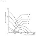
- FIG. 6 shows a graph having an abscissa representing a blown air volume at a unit of m 3 /min and an ordinate representing a static pressure at a unit of mmH 2 O, concerning an electromotive fan 109P0412H302 (40 square, and 28 mm thickness) manufactured by SANYO DENKI.
- the blown air volume of 0.3 m 3 /min based on the abscissa corresponds to a blown air volume of 5 liter/sec.
- the higher the voltage applied to the fan the larger the static pressure and the blown air volume.
- increased voltage possibly leads to a proportionally higher noise level, thereby hindering a calm sleep in case of usage such as in bedclothes.
- the supplied voltage and the static pressure are desirably restricted to levels of 12 V and 3 mmH 2 O or less, respectively.
- the static pressure is desirably 5 mmH 2 O or less.
- pressure of fan used herein shall mean a pressure difference between the ambient pressure in a room and a pressure within a flow connecting passage.
- FIG. 7 is a view showing an underlying futon according to a first embodiment of the present invention applied to cooling bedclothes.
- FIG. 7(a) is a plan view and FIG. 7(b) is a left side view of the cooling bedclothes.
- the cooling bedclothes of this embodiment have a structure comprising cooling flow passages or collective cooling flow passage 31 placed on a cushion 30.
- a flow connecting passage 32 is provided at the right side of a supine person, and a fan 33 of 60 square is provided at the end of the flow connecting passage 32 adjacent to the feet of the person.
- the cooling flow passage 31 has a lateral side constituting an air inlet at which the flow connecting passage 32 is provided (i.e., the right side of the lying person), and the other lateral side constituting an air outlet 34.
- the air outlet 34 is provided to face downwardly at the side of the cushion. This is to avoid a situation where the air outlet is closed such as by a covering futon.
- the fan 33 is provided to come close to the feet of the lying person, in view of a noise problem.
- an axial fan such as in view of a smaller noise, ensurance of required blown air volume, and reduction of air leakage from a fabric sheet.
- This controlling part 36 is provided with a switchable volume 37 and a timer 38.
- the switchable volume 37 is provided for switching on/off the operation of the fan, and for adjusting a blown air volume by varying a rotational speed of the fan.
- the timer 38 may be arbitrarily used by the lying person, or may be arranged such that the fan 33 is automatically stopped or the amount of blown air thereof is automatically reduced after an operation over a predetermined period of time of the fan 33, to thereby avoid overcooling.
- the c-type of planar spacer of FIG. 4 is adopted as the cooling flow passage 31.
- the longitudinal direction of the subspacers 11c is arranged in the widthwise direction of the underlying futon, in view of the air flowing direction.
- the upper side of this spacer is covered by a fabric or cloth 39, and the head side and foot side of the fabric 39 are bonded to the corresponding sides of the planar spacer.
- the ambient air drawn by the fan 33 flows through the flow connecting passage 32, enters the cooling flow passage 31, and thereafter flows from the left side toward the right side of the lying person.
- the larger thickness of the cooling flow passage 31 is advantageous so as to ensure a sufficient blown air volume on the order of 5 liter/sec even at a lower pressure. For example, when the thickness of the cooling flow passage is on the order of 10 mm to 15 mm, there can be ensured a sufficient amount of blown air at a lower pressure.
- the thickness of the cooling flow passage 31 may be reduced down to the order of 3 mm, such as when the blown air volume is reduced to a certain extent, the noise countermeasure is enhanced, or a fabric having a higher thread density resistant to higher pressures is adopted. Even when the thickness of the cooling flow passage 31 is reduced in such a way, the pressure within the flow connecting passage just after the fan 33 has a limit of 5 mmH 2 O.
- FIG. 8 is a view showing a chair seat cushion according to a second embodiment of the present invention applied to a cooling seat cushion.
- FIG. 8(a) is a plan view and
- FIG. 8(b) is a center cross-sectional view of the cooling seat cushion.
- FIG. 9 is a view showing the chair seat cushion according to the second embodiment of the present invention applied to the cooling seat cushion.
- Cooling seat cushion 40 of this embodiment is used in a manner placed on a chair 41 as shown in FIG. 9.
- the cooling seat cushion can be of course placed such as on a bench or sofa.
- the cooling seat cushion 40 of this embodiment basically constituted of two portions, i.e., a main portion 42 and a seat 43.
- the main portion 42 comprises a square spacer portion 44 of 400 mm length and 400 mm width, and a controlling part 46 provided at the rear side of the spacer portion 44.
- the spacer portion 44 has a top side provided with many projected subspacers.
- the main portion 42 comprising the spacer portion 44 and controlling part 46 is manufactured integrally by injection molding soft plastic. In view of the usage of the cushion to be placed on a chair, its entire size is limited to a length of approximately 500 mm and a width of approximately 500 mm.
- the e-type of FIG. 4 is adopted as the configuration of the spacer portion 44.
- Reduced thickness of the cooling flow passage leads to an increased flow rate to thereby enhance a cooling effect.
- extreme reduction is not practical in view of consumption of a battery, so that the lower limit of the cooling flow passage is on the order of 2 mm.
- the seat 43 is in the shape of bag to cover the whole of the spacer portion 44 except the controlling part 46. Only, the right side 43a in FIG. 8 is left open to thereby suck air. Any material can be used for the seat 43 if water vapor readily permeates through it, such as the aforementioned high-density fabric or a general fabric.
- the controlling part 46 is provided with a DC fan 47 of 40 square, a switch 48, and a battery 49.
- the battery 49 may be a normal dry cell, but it is preferably a rechargeable secondary battery such that it is recharged by the primary power source while the cooling seat cushion is not used.
- Pressure switch 50 is provided near the center of the main portion 42. The switch 48 and pressure switch 50 are connected in series such that the power from the battery is supplied to the DC fan 47 when both switches are turned on.
- the portion, where the controlling part 46 is provided, also acts as a flow connecting passage between the DC fan 47 and the cooling flow passage.
- the cooling seat cushion 40 When the cooling seat cushion 40 is to be used, it is placed such that the controlling part 46 is brought to the rear portion (at the backrest side) as shown in FIG. 9. Normally, the blowing outlet of the DC fan 47 is placed to face downwardly.
- the cooling seat cushion may be used in an upside-down manner, depending on the structure of an applicable chair.
- the sensor such as pressure switch 50 for detecting the seating is turned on.
- the switch 48 When the switch 48 is further turned on, the DC fan 47 rotates in a direction to suck the ambient air through the right side 43a of the seat 43. The air sucked through the side 43a flows through the cooling flow passage formed by the spacer portion 44, and is then exhausted downwardly by the DC fan 47.
- the amount of air to be flown may be on the order of 1 liter/sec which can be sufficiently conducted by a small fan such as 40 square.
- the ambient air at a temperature lower than the body temperature is caused to flow just below the buttocks to thereby increase the temperature gradient at the buttocks of the sitting person.
- the portion of the seat cushion contacting the buttocks will be never warmed by the body temperature, resulting in comfortable feeling. Since the e-type of spacer having many holes at the. bottom plate has been used in this embodiment, a sufficient cooling effect can be obtained even when the cooling seat cushion is used in an upside down manner.
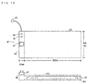
- FIG. 10 is a view showing a mat such as usable on a sofa or floor according to a third embodiment of the present invention applied to a cooling mat.
- FIG. 10(a) is a plan view and FIG. 10(b) is a cross-sectional view of the cooling mat, and
- FIG. 11 is a view showing which portion of a body is cooled by the mat.
- Cooling mat 60 of this embodiment is used in a manner to mainly cool the upper half of the body when a person rests such as on a floor or sofa as shown in FIG. 11.
- the basic structure of the cooling mat 60 of this embodiment basically comprises two portions, i.e., a main portion 62 and a seat 63, similarly to the cooling seat cushion according to the Embodiment 2.
- the main portion 62 comprises a rectangular spacer portion 64 of 900 mm length and 450 mm width, many subspacers provided on the top side of the spacer portion 64, and a controlling part 66 provided at the rear side of the spacer portion 64. These portions are integrally manufactured by injection molding soft plastic.
- the spacer portion 64 As the spacer portion 64, the e-type of FIG. 4 is adopted.
- the thickness of the cooling flow passage is in a range between 2 mm to 30 mm from the same reason with the aforementioned cooling seat cushion, and approximately 6 mm is suitable.
- the seat 63 is in the shape of bag to cover the whole of the spacer portion 64 except the controlling part 66. Only, the right side 63a in FIG. 10 is left open to thereby suck air. Any material can be used for the seat 63 if water vapor readily permeates through it, such as the aforementioned high-density fabric or a general fabric.
- the controlling part 66 is provided with a fan 67 of 50 square, a switchable volume 68, a plug 69 to be connected to the primary power source, and a timer 70.
- the controlling part 66 also acts as a flow connecting passage between the fan 67 and the cooling flow passage.
- the timer 70 may be arbitrarily used by the lying person, or may be arranged such that the fan 33 is automatically stopped or the amount of blown air thereof is automatically reduced after an operation over a predetermined period of time of the fan, to thereby avoid overcooling.
- the cooling mat When the cooling mat is to be used, it is placed under the upper half of the body on a floor or on a sofa, as shown in FIG. 11. Normally, the blowing outlet of the fan 67 is placed to face upwardly. However, the cooling mat may be used in an upside-down manner, when used such as on a bed.
- the switchable volume 68 When the switchable volume 68 is turned on, the fan 67 rotates in a direction to suck the ambient air through the right side 63a of the seat 63. The air sucked through the side 63a flows through the cooling flow passage formed by the spacer portion 64, and is then exhausted upwardly by the fan 67.
- the amount of air to be flown may be on the order of 3 liter/sec which can be sufficiently conducted by a small fan such as 50 square.
- the ambient air at a temperature lower than the body temperature is caused to flow such as just below the back and belly of the person to thereby increase the temperature gradient near the back and belly.
- the mat will be never warmed by the body temperature, resulting in comfortable feeling. Since the e-type of spacer having many holes at the bottom plate has been used in this embodiment, a sufficient cooling effect can be obtained even when the cooling mat is used in an upside down manner.
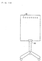
- FIG. 12 is a cross-sectional view of a chair according to a fourth embodiment of the present invention applied to a cooling chair
- FIG. 13 is a rear view of the cooling chair.
- the cooling chair of this embodiment includes a cooling flow passage 82 formed within a seat portion 80 and within a backrest 81.
- a DC fan 83 of 50 square adapted to rotate in a direction to outwardly discharge the air within the portions 80, 81.
- the blown air volume is suitably on the order of 2 liter/sec under a normal operating state.
- an air inlet 84 Provided at the front bottom portion of the seat portion 80 is an air inlet 84, and so is an inlet 85 at the upper rear portion of the backrest 81.
- the provision of the air inlet 84 at the front bottom portion of the seat portion 80 is to avoid occlusion of the air inlet 84 such as by feet and/or clothes.
- the cooling flow passage 82 is provided on the cushions for the seat portion 80 and backrest 81, so that a person sitting on the chair will feel suitable elasticity.
- the c-type of spacer in FIG. 4 is adopted to bear the load on the order of a body weight of a sitting person.
- Excessively reduced thickness of the cooling flow passage 82 leads to an increased pressure resulting in a larger amount of consumption of a battery 86.
- approximately 2 mm is the limit of the thickness.
- thicknesses of the cooling flow passage exceeding 30 mm are impractical, in view of the cooling principle of this method. Practically, approximately 5 mm is suitable.
- the battery 86 for energizing the DC fan 83 is provided within the backrest 81 at the rear side of the seat portion 80. This battery 86 can be charged from the primary power source while the chair is not used, by a battery charger 88 of a type for inserting a plug into a jack 87.
- a pressure switch 90 which is turned on when a person sits thereon.
- Switchable volume 89 provided at the rear side of the seat portion 80 is connected in series to the pressure switch. When the switchable volume 89 is turned on where the pressure switch 90 has been turned on by a sitting person thereon, the DC fan 83 is rotated. The revolution speed of this fan can be changed by rotating the switchable volume 89 to thereby adjust the blown air volume.
- the ambient air at a temperature lower than the body temperature is caused to flow such as just below the back and buttocks of the person to thereby increase the temperature gradient near the back and buttocks.
- the portion of the cooling chair contacting the buttocks and back will be never warmed by the body temperature, resulting in comfortable feeling.
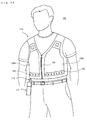
- FIG. 14 is a perspective view of a piece of clothing in a worn state according to a fifth embodiment of the present invention applied to cooling clothes.
- the cooling clothing 101 of this embodiment comprises a vest type main portion 110, and a controlling part 111 connected to the main portion 110 via cable 112.
- the main portion 110 can be worn in a manner similarly to a normal vest, such that a front fastener 132 of the main portion is opened, the arms of a person are sequentially passed through the sleeves, and then the fastener 132 is zipped up.
- the main portion 110 is provided with front two and rear two pieces, totally four pieces, of cooling sheets 120a, 120b, 120c and 120d (rear cooling sheets 120c and 120d are omitted in the drawing). These cooling sheets are independent from one another. The provision of multiple cooling sheets is to facilitate the formation of the spacer. Should the whole of the clothing be formed of a single cooling sheet, it is difficult and impractical to form a flexible spacer well fitting to a body.
- Those portions of the main portion 110 except the cooling sheets 120a through 120d are formed of an elastic fabric such as a material of polyurethane called Spandex. By sewingly connect this elastic fabric and four pieces of cooling sheets 120a through 120d, the cooling clothing 101 of the vest type is completed. In this case, the backsides of the cooling sheets 120 can be closely contacted with the wearer, by selecting a smaller size of the cooling clothing 101 so that the elastic fabric is slightly expanded upon wearing.
- an elastic fabric such as a material of polyurethane called Spandex.
- Each of the four pieces of cooling sheets 120a through 120d is provided with a DC fan 121 at the upper portion thereof and an air inlet 122 at the lower portion thereof. Further, a cooling flow passage is formed between the air inlet 122 and the DC fan 121.
- the DC fan 121 rotates in a direction to discharge air outwardly. Namely, rotation of the DC fan 121 causes air to be sucked via air inlet 122, to raise through the cooling flow passage, and then to be discharged by the DC fan 121.
- Each DC fan 121 is attached to the corresponding cooling sheet such as by a magic tape detachably. This allows the DC fan 121 to be readily removed such as upon washing the cooling clothes, resulting in convenience.
- the controlling part 111 is provided with a battery 125 and a switchable volume 126.
- the battery 125 may be a normal dry cell or a rechargeable secondary battery.
- the role of the switchable volume 126 is identical with those in the aforementioned embodiments.
- the b-type of spacer is adopted as one for forming the cooling flow passage. This is because the spacer will not bear a larger load in case of clothes, so that a lighter one is advantageous.
- the b-type of planar spacer of FIG. 4 is manufactured by injection molding a thermoplastic elastomer. By covering this spacer by an upper fabric, the cooling flow passage is formed. Thermoplastic elastomers have rubber-like characteristics after formation, thus have sufficient elasticity. In view of the consumption of the battery 125, the thickness of the cooling flow passage is limited to approximately 2 mm at the thinnest.
- FIG. 15 is a cross-sectional view of one of a pair of shoes according to a sixth embodiment of the present invention applied to cooling shoes.
- cooling shoe 140 of this embodiment is provided with a cooling flow passage 141 at the shoe bottom portion, an air inlet 142 at the toe portion, an air outlet 143 at the heel portion, and a DC fan 144 rotated in a direction for discharging air backwardly of the heel.
- a battery 145 for energizing the DC fan 144.
- This battery 145 may be a normal dry cell or a rechargeable secondary battery.
- the cooling shoe 140 of this embodiment is provided with a foot sensor 146 at a bottom portion within the shoe.
- This sensor constitutes a switch which is turned on by entrance of foot and turned off by withdrawal of foot. Thus, waste of power consumption during disuse of the shoe is avoided.
- the foot sensor 146 such as a pressure switch may be adopted, but any other type of sensor may be adopted insofar as it can detect the used state of the shoe.
- Wearing the cooling shoe 140 of this embodiment causes the foot sensor 146 to be turned on to thereby rotate the DC fan 144. Then, air is sucked through the air inlet 142, flows leftwardly through the cooling flow passage 141. At this time, an air layer having a temperature same with that of the ambient air is formed adjacently to the surface of the foot sole, thereby increasing the temperature gradient at this portion. Thus, even during midsummer, the interior of the shoes never become sweaty, thereby providing comfortable feeling.
- FIG. 16 is a plan view of a covering futon according to a seventh embodiment of the present invention applied to cooling bedclothes
- FIG. 17 is a view showing a structure of a spacer of the seventh embodiment.
- a flow connecting passage 150 at the right side of a supine person and an axial fan 151 of 60 square at the foot end of the passage 150. That side (right side of the supine person) of the cooling flow passage 152 which is provided with the flow connecting passage 150 acts as an air inlet, and the opposite side of the passage 152 acts as an air outlet.
- the fan 151 is arranged at the foot side of the lying person, in view of a noise problem.
- the total size of the cooling flow passage 152 and flow connecting passage 150 includes such as a length of 1,800 mm and a width of 1,200 mm.
- planar spacer obtained by slightly modifying the b-type one of FIG. 4, as the planar spacer in this embodiment.
- This planar spacer is further lightened, by rectangular holes instead of circular ones.
- the cooling flow passage 152 is formed by covering the whole of the planar spacer by a bag-like fabric. The air drawn from the surroundings by the fan 151 into the cooling flow passage 152 flows laterally within the cooling flow passage 152, and finally exits from the outlet at the opposite side of the passage 152. In this way, an air layer having a temperature same with that of the ambient air is formed adjacently to the body surface to thereby increase the temperature gradient there, resulting in comfortable feeling even at a hot night.
- the bag-like fabric for forming the cooling flow passage 152 it is desirable to adopt the aforementioned high-density fabric.
- its overall surface area is large so that excessively higher pressures at the portion just after the fan 151, i.e., at the flow connecting passage 150 lead to a problem of substantial leakage of air on its way. Further, excessively higher pressures also lead to a considerable noise problem.
- the larger thickness of the cooling flow passage 152 is advantageous so as to ensure a sufficient blown air volume on the order of 5 liter/sec even at a lower pressure.
- the thickness of the cooling flow passage is on the order of 10 mm to 15 mm, there can be ensured a sufficient amount of blown air at a lower pressure.
- the thickness of the cooling flow passage 152 may be reduced down to the order of 3 mm, such as when the blown air volume is reduced to a certain extent, the noise countermeasure for the fan 151 is enhanced, or a fabric having a higher thread density resistant to higher pressures is adopted. Even when the thickness of the cooling flow passage 152 is reduced in such a way, the pressure just after the fan 151 has a limit of 5 mmH 2 O.
- a timer to avoid overcooling of a lying person.
- a timer may be arbitrarily used by the lying person, or may be arranged such that the fan is automatically stopped or the amount of blown air thereof is automatically reduced after an operation over a predetermined period of time of the fan.
- FIG. 18 is a view showing a pillow according to an eighth embodiment of the present invention applied to cooling bedclothes, and (a) is a cross-sectional view and (b) is a plan view thereof. Further, FIG. 19 is a cross-sectional view showing a sound-insulating countermeasure for a DC fan of the eighth embodiment.
- the cooling bedclothes of this embodiment has a structure comprising a cooling flow passage 161 placed on a cushion 160.
- a flow connecting passage 162 at the upper portion of FIG. 18(b) (the left portion of FIG. 18(a))
- a DC fan 163 of 50 square is provided at the center portion of the passage 162.
- This DC fan 163 is an axial fan, which rotates in a direction to suck air through the underside of the fan and feeds the air to the flow connecting passage 162 and cooling flow passage 161, and finally discharges the air at the opposite side of the passage 161.
- the d-type of planar spacer in FIG. 4 is adopted as the spacer for forming the cooling flow passage 161.
- This planar spacer is manufactured by injection molding soft polyethylene.
- a jack 164 for insertion of a DC adapter at the lateral portion of the pillow, and the DC fan 163 is supplied with power from the jack.
- a switchable volume 165 is provided at the lateral portion of the pillow. The switchable volume 165 serves to turn on/off the operation of the fan, and to vary the rotational speed thereof to thereby adjust the blown air volume.
- the DC fan 163 When the pillow according to the cooling bedclothes of this embodiment is used to place thereon a head of a lying person and the switchable volume 165 is turned on, the DC fan 163 is rotated. This causes air to be sucked into the air inlet at the lower side of the DC fan 163, and to flow through the flow connecting passage 162 and cooling flow passage 161 rightwardly in FIG. 18(a). At this time, an air layer having a temperature same with that of the ambient air is formed adjacently to the surface of the person's head, to thereby increase the temperature gradient at this portion. Thus, there is provided a calm sleep even during midsummer time.
- cooling bedclothes, cooling seat cushion, cooling mat, cooling chair, cooling clothing and cooling shoes of the present invention there is formed, at a location extremely adjacent to the body surface of a person, an air layer having a temperature equal to that in the room without lowering the temperature of the whole room, thereby forcibly increasing the temperature gradient near the body surface to thereby increase the extent of heat release from the body.
- any devices for cooling air are omitted to thereby reduce cost, without any uncomfortable feeling due to direct blowing of cooled air, thereby resulting in feeling of natural coolness.
- the present invention utilizes such a cooling effect to form the cooling flow passages in a substantially parallel and planar manner at the portion of an article adjacent to the body, and causes the ambient air at a temperature lower than the body temperature to flow through the cooling flow passages substantially parallelly to the body surface to thereby cool the body.
- the present invention can be utilized in any articles such as bedclothes, mat, chair seat cushion, chair, clothing and shoes to which the cooling effect can be applied.
Landscapes
- Health & Medical Sciences (AREA)
- General Health & Medical Sciences (AREA)
- Public Health (AREA)
- Engineering & Computer Science (AREA)
- Epidemiology (AREA)
- Biomedical Technology (AREA)
- Animal Behavior & Ethology (AREA)
- Textile Engineering (AREA)
- Environmental & Geological Engineering (AREA)
- Heart & Thoracic Surgery (AREA)
- Vascular Medicine (AREA)
- Life Sciences & Earth Sciences (AREA)
- Physical Education & Sports Medicine (AREA)
- Veterinary Medicine (AREA)
- Mattresses And Other Support Structures For Chairs And Beds (AREA)
- Outerwear In General, And Traditional Japanese Garments (AREA)
- Chair Legs, Seat Parts, And Backrests (AREA)
- Bedding Items (AREA)
- Footwear And Its Accessory, Manufacturing Method And Apparatuses (AREA)
Abstract
Description
Claims (8)
- A cooling underlying futon comprising:cooling flow passages formed in a substantially parallel and planar manner adjacent to that portion of the futon on an elastic member, which contacts a body of a person;an inlet for drawing air into said cooling flow passages;an outlet for discharging the air from said cooling flow passages;at least one electromotive fan provided at at least one of said inlet and outlet; anda flow connecting passage provided between said electromotive fan and said cooling flow passages;whereby the ambient air at a temperature lower than the body temperature is caused by said electromotive fan to flow through said cooling flow passages substantially parallelly to the body surface so as to increase the temperature gradient between the body and said cooling flow passages in order to release the heat emitted from the body to thereby cool the body; andwhereinsaid cooling flow passages are formed from a spacer and a sheet-like material, said sheet-like material being arranged between said spacer and the body and having a thickness of 5 mm or less; andsaid spacer is formed from a common member and a plurality of physically contiguous subspacers formed on said common member integrally with the same, said subspacers being configured such that said cooling flow passages have a thickness of 3 mm or more.
- A cooling seat cushion usable on a seat portion, said cooling seat cushion comprising:cooling flow passages formed in a substantially parallel and planar manner adjacent to that portion of said cooling seat cushion, which contacts a body of a person;an inlet for drawing air into said cooling flow passages;an outlet for discharging the air from said cooling flow passages;at least one electromotive fan provided at at least one of said inlet and outlet;a battery for energizing said electromotive fan; anda flow connecting passage provided between said electromotive fan and said cooling flow passages;whereby the ambient air at a temperature lower than the body temperature is caused by said electromotive fan to flow through said cooling flow passages substantially parallelly to the body surface so as to increase the temperature gradient between the body and said cooling flow passages in order to release the heat emitted from the body to thereby cool the body; andwhereinsaid cooling flow passages are formed from a spacer and a sheet-like material, said sheet-like material being arranged between said spacer and the body and having a thickness of 5 mm or less; andsaid spacer is formed from a common member and a plurality of physically contiguous subspacers formed on said common member integrally with the same, said subspacers being configured such that said cooling flow passages have a thickness of 2mm or more.
- A cooling mat comprising:cooling flow passages formed in a substantially parallel and planar manner adjacent to that portion of said cooling mat, which contacts a body of a person;an inlet for drawing air into said cooling flow passages;an outlet for discharging the air from said cooling flow passages;at least one electromotive fan provided at at least one of said inlet and outlet; anda flow connecting passage provided between said electromotive fan and said cooling flow passages;whereby the ambient air at a temperature lower than the body temperature is caused by said electromotive fan to flow through said cooling flow passages substantially parallelly to the body surface so as to increase the temperature gradient between the body and said cooling flow passages in order to release the heat emitted from the body to thereby cool the body; andwhereinsaid cooling flow passages are formed from a spacer and a sheet-like material, said sheet-like material being arranged between said spacer and the body and having a thickness of 5 mm or less; andsaid spacer is formed from a common member and a plurality of physically contiguous subspacers formed on said common member integrally with the same, said subspacers being configured such that said cooling flow passages have a thickness of 2mm or more.
- A cooling chair comprising:cooling flow passages formed in a substantially parallel and planar manner adjacent to that portion of a seat portion of said cooling chair, which contacts a body of a person;an inlet for drawing air into said cooling flow passages;an outlet for discharging the air from said cooling flow passages;at least one electromotive fan provided at at least one of said inlet and outlet; anda flow connecting passage provided between said electromotive fan and said cooling flow passages;whereby the ambient air at a temperature lower than the body temperature is caused by said electromotive fan to flow through said cooling flow passages substantially parallelly to the body surface so as to increase the temperature gradient between the body and said cooling flow passages in order to release the heat emitted from the body to thereby cool the body; andwhereinsaid cooling flow passages are formed from a spacer and a sheet-like material, said sheet-like material being arranged between said spacer and the body and having a thickness of 5 mm or less; andsaid spacer is formed from a common member and a plurality of physically contiguous subspacers formed on said common member integrally with the same, said subspacers being configured such that said cooling flow passages have a thickness of 2mm or more.
- A piece of cooling clothing comprising:a plurality of mutually independent cooling flow passages formed in a substantially parallel and planar manner adjacent to that portion of said cooling clothing, which contacts a body of a person;an elastic material for connecting said plurality of cooling flow passage;an inlet for drawing air into said cooling flow passages;an outlet for discharging the air from said cooling flow passages;at least one electromotive fan provided at at least one of said inlet and outlet; anda battery for energizing said electromotive fan;whereby the ambient air at a temperature lower than the body temperature is caused by said electromotive fan to flow through said cooling flow passages substantially parallelly to the body surface so as to increase the temperature gradient between the body and said cooling flow passages in order to release the heat emitted from the body to thereby cool the body; andwhereinsaid cooling flow passages are formed from a spacer and a sheet-like material, said sheet-like material being arranged between said spacer and the body and having a thickness of 5 mm or less; andsaid spacer is formed from a common member and a plurality of physically contiguous subspacers formed on said common member integrally with the same, said subspacers being configured such that said cooling flow passages have a thickness of 2mm or more.
- A cooling shoe comprising:cooling flow passages formed in a substantially parallel and planar manner adjacent to that portion of said cooling shoe, which contacts a foot sole of a person;an inlet for drawing air into said cooling flow passages;an outlet for discharging the air from said cooling flow passages;an electromotive fan provided at one of said inlet and outlet;a battery for energizing said electromotive fan; anda flow connecting passage provided between said electromotive fan and said cooling flow passages;whereby the ambient air at a temperature lower than the body temperature is caused by said electromotive fan to flow through said cooling flow passages substantially parallelly to the foot sole so as to increase the temperature gradient between the foot sole and said cooling flow passages in order to release the heat emitted from the foot sole to thereby cool the foot sole; andwhereinsaid cooling flow passages are formed from a spacer and a sheet-like material, said sheet-like material being arranged between said spacer and the body and having a thickness of 5 mm or less; andsaid spacer is formed from a common member and a plurality of physically contiguous subspacers formed on said common member integrally with the same, said subspacers being configured such that said cooling flow passages have a thickness of 2mm or more.
- A cooling covering futon comprising:cooling flow passages formed in a substantially parallel and planar manner adjacent to that portion of said cooling covering futon, which contacts a body of a person;an inlet for drawing air into said cooling flow passages;an outlet for discharging the air from said cooling flow passages;at least one electromotive fan provided at at least one of said inlet and outlet; anda flow connecting passage provided between said electromotive fan and said cooling flow passages;whereby the ambient air at a temperature lower than the body temperature is caused by said electromotive fan to flow through said cooling flow passages substantially parallelly to the body surface so as to increase the temperature gradient between the body and said cooling flow passages in order to release the heat emitted from the body to thereby cool the body; andwhereinsaid cooling flow passages are formed from a spacer and a sheet-like material, said sheet-like material being arranged between said spacer and the body and having a thickness of 10 mm or less; andsaid spacer is formed from a common member and a plurality of physically contiguous subspacers formed on said common member integrally with the same, said subspacers being configured such that said cooling flow passages have a thickness of 3mm or more.
- A cooling pillow comprising:cooling flow passages formed in a substantially parallel and planar manner adjacent to that portion of said cooling pillow, which contacts a head of a person;a cushioning member for carrying said cooling flow passage thereon;an inlet for drawing air into said cooling flow passages;an outlet for discharging the air from said cooling flow passages;at least one electromotive fan provided at at least one of said inlet and outlet;soundproof means provided for said electromotive fan; anda flow connecting passage provided between said electromotive fan and said cooling flow passages;whereby the ambient air at a temperature lower than the body temperature is caused by said electromotive fan to flow through said cooling flow passages substantially parallelly to the head surface so as to increase the temperature gradient between the head and said cooling flow passages in order to release the heat emitted from the head to thereby cool the head; andwhereinsaid cooling flow passages are formed from a spacer and a sheet-like material, said sheet-like material being arranged between said spacer and the body and having a thickness of 5 mm or less; andsaid spacer is formed from a common member and a plurality of physically contiguous subspacers formed on said common member integrally with the same, said subspacers being configured such that said cooling flow passages have a thickness of 2mm or more.
Applications Claiming Priority (1)
| Application Number | Priority Date | Filing Date | Title |
|---|---|---|---|
| PCT/JP1999/004612 WO2001015573A1 (en) | 1999-08-26 | 1999-08-26 | Cooled bedding, cooled cushion, cooled mat, cooled chair, cooled clothes and cooled shoes |
Publications (2)
| Publication Number | Publication Date |
|---|---|
| EP1142515A1 true EP1142515A1 (en) | 2001-10-10 |
| EP1142515A4 EP1142515A4 (en) | 2002-05-02 |
Family
ID=14236557
Family Applications (1)
| Application Number | Title | Priority Date | Filing Date |
|---|---|---|---|
| EP99940498A Withdrawn EP1142515A4 (en) | 1999-08-26 | 1999-08-26 | Cooled bedding, cooled cushion, cooled mat, cooled chair, cooled clothes and cooled shoes |
Country Status (7)
| Country | Link |
|---|---|
| US (1) | US6779592B1 (en) |
| EP (1) | EP1142515A4 (en) |
| JP (1) | JP3419403B2 (en) |
| CN (1) | CN1111377C (en) |
| AU (1) | AU754200B2 (en) |
| CA (1) | CA2347137A1 (en) |
| WO (1) | WO2001015573A1 (en) |
Cited By (11)
| Publication number | Priority date | Publication date | Assignee | Title |
|---|---|---|---|---|
| EP1552759A4 (en) * | 2002-07-10 | 2007-08-15 | Seft Dev Lab Co Ltd | Cooling clothes |
| EP1698242A4 (en) * | 2003-12-25 | 2008-06-18 | Seft Dev Lab Co Ltd | Air-conditioned garment |
| EP1994840A1 (en) * | 2007-05-25 | 2008-11-26 | Hexonia GmbH | Ventilation device for human body |
| EP1649765A4 (en) * | 2003-08-01 | 2009-05-13 | Seft Dev Lab Co Ltd | Cooling clothes |
| KR100918973B1 (en) * | 2007-09-10 | 2009-09-25 | 임승엽 | Multi purpose dutch wife |
| EP2679144A1 (en) | 2012-06-27 | 2014-01-01 | De Domenico, Andrea | Blade of a laryngoscope, or similar devices, with a progressive spreading mechanism |
| WO2014106119A1 (en) * | 2012-12-27 | 2014-07-03 | Select Comfort Corporation | Distibution pad for a temperature control system |
| CN105201270A (en) * | 2014-11-24 | 2015-12-30 | 陈鸿 | Bedding articles and other articles cooled by refrigerator |
| EP2869800A4 (en) * | 2012-07-05 | 2016-03-30 | Stryker Corp | PROTECTION FOR SUPPORTING A PRESSURE WOUND |
| DK178884B1 (en) * | 2014-10-06 | 2017-04-24 | Foday Musa Fofonah | Anti sweat shoe |
| US10772438B2 (en) | 2017-08-23 | 2020-09-15 | Sleep Number Corporation | Air system for a bed |
Families Citing this family (35)
| Publication number | Priority date | Publication date | Assignee | Title |
|---|---|---|---|---|
| WO2002067707A1 (en) * | 2001-02-23 | 2002-09-06 | Seft Development Laboratory Co.,Ltd. | Cooling cloths |
| EP1535547A1 (en) * | 2002-08-06 | 2005-06-01 | Seft Development Laboratory Co. Ltd. | Wind passage for dehumidifying apparatus |
| CN1310603C (en) * | 2002-08-23 | 2007-04-18 | 颜文法 | Flat knitting machine collar capable of keeping collar shape |
| WO2004017773A1 (en) * | 2002-08-26 | 2004-03-04 | Seft Development Laboratory Co.,Ltd. | Air conditioned clothes unit |
| JP4508559B2 (en) * | 2003-06-19 | 2010-07-21 | 株式会社ケープ | mattress |
| EP1874112A2 (en) * | 2005-04-12 | 2008-01-09 | Hyperion Innovations, Inc. | Portable heated padding for pets |
| US20070013213A1 (en) * | 2005-04-12 | 2007-01-18 | Hyperion Innovations, Inc. | Portable heated seating |
| JP4739882B2 (en) * | 2005-09-22 | 2011-08-03 | 株式会社ボンフォーム | mattress |
| US20090312676A1 (en) * | 2006-02-02 | 2009-12-17 | Tylerton International Inc. | Metabolic Sink |
| US20080033518A1 (en) * | 2006-02-02 | 2008-02-07 | Tylerton International Inc. | Thermoregulating units |
| TWI494070B (en) * | 2006-04-18 | 2015-08-01 | Seft Dev Lab Co Ltd | Spacer and air conditioning mat |
| WO2007134189A2 (en) * | 2006-05-10 | 2007-11-22 | Board Of Regents, The University Of Texas System | Detecting tumor biomarker in oral cancer |
| US7914611B2 (en) | 2006-05-11 | 2011-03-29 | Kci Licensing, Inc. | Multi-layered support system |
| CN100446702C (en) * | 2007-06-14 | 2008-12-31 | 江苏梦兰集团有限公司 | Stereo gauze type down-feather quilt |
| JP5997899B2 (en) | 2008-07-18 | 2016-09-28 | ジェンサーム インコーポレイテッドGentherm Incorporated | Air conditioned bed assembly |
| RU2516793C2 (en) * | 2008-11-19 | 2014-05-20 | Хантлей Текнолоджи Лимитед | Multilayer support system and related method |
| WO2011032288A1 (en) * | 2009-09-21 | 2011-03-24 | Mawashi Vêtements De Protection Inc. | Personal cooling system and method |
| US20110094029A1 (en) * | 2009-10-26 | 2011-04-28 | Michael Johnson | Comforter With Low Heat Retention Characteristic And Method Of Making |
| CN101731871B (en) * | 2010-01-09 | 2012-04-11 | 蒋孝秋 | Draughty chair |
| CN101919632B (en) * | 2010-08-13 | 2012-07-04 | 广州爱奇实业有限公司 | Ventilation seat |
| US8918930B2 (en) | 2011-01-04 | 2014-12-30 | Huntleigh Technology Limited | Methods and apparatuses for low-air-loss (LAL) coverlets and airflow units for coverlets |
| AU2012286707B2 (en) | 2011-07-28 | 2017-04-06 | Arjo Ip Holding Ab | Multi-layered support system |
| US20130031722A1 (en) * | 2011-08-01 | 2013-02-07 | Tin Cheung Wong | Air-conditioning bed |
| EP2763642B1 (en) | 2011-10-03 | 2016-11-16 | Huntleigh Technology Limited | Multi-layered support system with electrically conductive spacer material |
| US20130212808A1 (en) | 2012-02-21 | 2013-08-22 | Charles A. Lachenbruch | Topper with Targeted Fluid Flow Distribution |
| EP3146869A4 (en) * | 2014-05-21 | 2018-01-24 | SFT Laboratory Co., Ltd. | Air-circulating mat |
| US10342358B1 (en) | 2014-10-16 | 2019-07-09 | Sleep Number Corporation | Bed with integrated components and features |
| CN104665404B (en) * | 2015-03-04 | 2017-06-20 | 薛芳 | A kind of Intelligent refrigeration quilt mattress, sleeping bag |
| WO2016158759A1 (en) | 2015-03-27 | 2016-10-06 | テイ・エス テック株式会社 | Chair |
| JP6600966B2 (en) * | 2015-03-31 | 2019-11-06 | テイ・エス テック株式会社 | Chair |
| US10363852B2 (en) * | 2016-09-15 | 2019-07-30 | Ford Global Technologies, Llc | Apparatus and method for customizing a vehicle seat |
| US20200329882A1 (en) * | 2017-11-21 | 2020-10-22 | Vincenzo Buoninfante | Mattress |
| CN108969178B (en) * | 2018-06-14 | 2020-07-14 | 浙江工贸职业技术学院 | A solar thermal shoe |
| WO2020214219A1 (en) * | 2019-04-16 | 2020-10-22 | Sleep Number Corporation | Pillow with wireless charging |
| KR200490484Y1 (en) * | 2019-06-03 | 2019-11-18 | 주식회사 지오클라비스 | Functional pillow |
Family Cites Families (21)
| Publication number | Priority date | Publication date | Assignee | Title |
|---|---|---|---|---|
| DE1933456A1 (en) * | 1969-07-02 | 1971-06-03 | Eisenburger Kuno Dipl Ing | Two- or multi-layer edition, cover and the like. for seat and lounge furniture |
| US3757366A (en) * | 1971-08-18 | 1973-09-11 | W Sacher | Cushion for preventing and alleviating bedsores |
| JPS54178609U (en) * | 1978-06-05 | 1979-12-17 | ||
| JPS5521947A (en) * | 1978-08-02 | 1980-02-16 | Nissan Motor | Seat cover |
| JPS56145819A (en) * | 1980-04-11 | 1981-11-12 | Matsushita Electric Industrial Co Ltd | Separate type electronic pillow |
| JPS61266603A (en) * | 1985-05-14 | 1986-11-26 | 松下電器産業株式会社 | Garment with air blowing function |
| JPS647807U (en) * | 1987-07-04 | 1989-01-17 | ||
| JPS6416852U (en) * | 1987-07-22 | 1989-01-27 | ||
| JPS6428466A (en) * | 1987-07-23 | 1989-01-31 | Matsushita Electric Works Ltd | Cooler |
| US4821354A (en) * | 1988-03-21 | 1989-04-18 | Little Donald E | Portable cooling pool, beach or car seat mat |
| FR2641956B1 (en) | 1989-01-20 | 1994-06-03 | Guillotin Jean Pierre | VENTILATED COVER FOR VEHICLE SEAT |
| IT1246506B (en) * | 1990-12-12 | 1994-11-19 | Fimac Spa | COOLING GARMENT, IN PARTICULAR OF THE JACKET OR SIMILAR TYPE. |
| US5329656A (en) * | 1992-12-03 | 1994-07-19 | Dennis V. Leggett | Insulated puncture resistant inflatable mattress |
| JPH07313300A (en) * | 1994-05-30 | 1995-12-05 | K & Jii:Kk | Temperature control sheet device |
| JP2939420B2 (en) * | 1994-08-22 | 1999-08-25 | アポロ寝装株式会社 | Method of manufacturing a futon with an air introduction member and a futon |
| JP3061360B2 (en) * | 1995-12-11 | 2000-07-10 | 裕子 鈴木 | Air control floor cover |
| US5954129A (en) * | 1996-02-14 | 1999-09-21 | Takahashi; Kei | Flow control unit |
| JP3665975B2 (en) * | 1996-02-16 | 2005-06-29 | 敬 高橋 | Fluid regulation conveying means |
| GB9727469D0 (en) * | 1997-12-30 | 1998-02-25 | Sugden Kurt D | Fabric material |
| JPH11229225A (en) * | 1998-02-16 | 1999-08-24 | Minoru Tagami | Ventilator attached to tool worn on body, and tool worn on body with ventilator |
| US6516624B1 (en) | 1998-07-30 | 2003-02-11 | Seft Development Laboratory Co., Ltd. | Cooling pillow |
-
1999
- 1999-08-26 CN CN99813558A patent/CN1111377C/en not_active Expired - Fee Related
- 1999-08-26 WO PCT/JP1999/004612 patent/WO2001015573A1/en not_active Ceased
- 1999-08-26 JP JP2001502644A patent/JP3419403B2/en not_active Expired - Fee Related
- 1999-08-26 EP EP99940498A patent/EP1142515A4/en not_active Withdrawn
- 1999-08-26 CA CA002347137A patent/CA2347137A1/en not_active Abandoned
- 1999-08-26 US US09/830,411 patent/US6779592B1/en not_active Expired - Fee Related
- 1999-08-26 AU AU54438/99A patent/AU754200B2/en not_active Ceased
Cited By (18)
| Publication number | Priority date | Publication date | Assignee | Title |
|---|---|---|---|---|
| EP1552759A4 (en) * | 2002-07-10 | 2007-08-15 | Seft Dev Lab Co Ltd | Cooling clothes |
| EP1649765A4 (en) * | 2003-08-01 | 2009-05-13 | Seft Dev Lab Co Ltd | Cooling clothes |
| EP1698242A4 (en) * | 2003-12-25 | 2008-06-18 | Seft Dev Lab Co Ltd | Air-conditioned garment |
| EP1994840A1 (en) * | 2007-05-25 | 2008-11-26 | Hexonia GmbH | Ventilation device for human body |
| EP2016843A1 (en) | 2007-05-25 | 2009-01-21 | Hexonia GmbH | Garment with a ventilation device for a human body |
| KR100918973B1 (en) * | 2007-09-10 | 2009-09-25 | 임승엽 | Multi purpose dutch wife |
| EP2679144A1 (en) | 2012-06-27 | 2014-01-01 | De Domenico, Andrea | Blade of a laryngoscope, or similar devices, with a progressive spreading mechanism |
| EP2869800A4 (en) * | 2012-07-05 | 2016-03-30 | Stryker Corp | PROTECTION FOR SUPPORTING A PRESSURE WOUND |
| US9131781B2 (en) | 2012-12-27 | 2015-09-15 | Select Comfort Corporation | Distribution pad for a temperature control system |
| WO2014106119A1 (en) * | 2012-12-27 | 2014-07-03 | Select Comfort Corporation | Distibution pad for a temperature control system |
| US10194752B2 (en) | 2012-12-27 | 2019-02-05 | Sleep Number Corporation | Distribution pad for a temperature control system |
| US11083308B2 (en) | 2012-12-27 | 2021-08-10 | Sleep Number Corporation | Distribution pad for a temperature control system |
| US12383070B2 (en) | 2012-12-27 | 2025-08-12 | Sleep Number Corporation | Distribution pad for a temperature control system |
| DK178884B1 (en) * | 2014-10-06 | 2017-04-24 | Foday Musa Fofonah | Anti sweat shoe |
| CN105201270A (en) * | 2014-11-24 | 2015-12-30 | 陈鸿 | Bedding articles and other articles cooled by refrigerator |
| US10772438B2 (en) | 2017-08-23 | 2020-09-15 | Sleep Number Corporation | Air system for a bed |
| US11553802B2 (en) | 2017-08-23 | 2023-01-17 | Sleep Number Corporation | Air system for a bed |
| US12279698B2 (en) | 2017-08-23 | 2025-04-22 | Sleep Number Corporation | Layer assembly for a bed to distribute air |
Also Published As
| Publication number | Publication date |
|---|---|
| CN1331568A (en) | 2002-01-16 |
| CA2347137A1 (en) | 2001-03-08 |
| US6779592B1 (en) | 2004-08-24 |
| EP1142515A4 (en) | 2002-05-02 |
| JP3419403B2 (en) | 2003-06-23 |
| CN1111377C (en) | 2003-06-18 |
| AU754200B2 (en) | 2002-11-07 |
| WO2001015573A1 (en) | 2001-03-08 |
| AU5443899A (en) | 2001-03-26 |
Similar Documents
| Publication | Publication Date | Title |
|---|---|---|
| US6779592B1 (en) | Cooling futon | |
| US6786273B2 (en) | Cooling seat cushion | |
| JPWO2001015573A1 (en) | Cooling bedding, cooling cushions, cooling mats, cooling chairs, cooling clothing, and cooling shoes | |
| US8640281B2 (en) | Non-inflatable temperature control system | |
| ES2826991T3 (en) | Body support with fluid system and method of operation of the fluid system | |
| ES2534286T3 (en) | Air-conditioned bed | |
| US6668405B1 (en) | Variable pressure relief inflated cushion | |
| US6619382B1 (en) | Spacer for cooling devices | |
| JP2000512175A (en) | Seats, backrests and chaise lounges | |
| CN100500058C (en) | Dehumidifying pad | |
| JP2007007378A (en) | Temperature adjusting mat | |
| KR100826793B1 (en) | Hot and Cold Bed with Heat Transfer | |
| KR20230154348A (en) | Breathable air mat capable of floating partially for preventing bedsores | |
| CN101420889B (en) | Air conditioned mat | |
| US10925784B1 (en) | Lifting pad for wheelchair | |
| WO2018001969A1 (en) | Airflow control for head support | |
| KR102451799B1 (en) | Air cooling mat | |
| JP7773538B2 (en) | Adjustable base element for reclining furniture and reclining furniture | |
| TW558427B (en) | Cooling device | |
| KR102187919B1 (en) | Cool or hot water combination type mat | |
| CN221671324U (en) | Spring mattress with adjustable hardness and air heating function | |
| CN222473980U (en) | Ventilated cushion | |
| WO2006045220A1 (en) | Refrigerating/heating apparatus | |
| KR20230164252A (en) | Ventilated air mat for seats capable of pressure dispersion and sequential shift flotation | |
| CN120660984A (en) | Novel mattress for pressing and rubbing environment-friendly material space light foam ball |
Legal Events
| Date | Code | Title | Description |
|---|---|---|---|
| PUAI | Public reference made under article 153(3) epc to a published international application that has entered the european phase |
Free format text: ORIGINAL CODE: 0009012 |
|
| 17P | Request for examination filed |
Effective date: 20010427 |
|
| AK | Designated contracting states |
Kind code of ref document: A1 Designated state(s): AT BE CH CY DE DK ES FI FR GB GR IE IT LI LU MC NL PT SE |
|
| AX | Request for extension of the european patent |
Free format text: AL;LT;LV;MK;RO;SI |
|
| A4 | Supplementary search report drawn up and despatched |
Effective date: 20020314 |
|
| AK | Designated contracting states |
Kind code of ref document: A4 Designated state(s): AT BE CH CY DE DK ES FI FR GB GR IE IT LI LU MC NL PT SE |
|
| 17Q | First examination report despatched |
Effective date: 20030224 |
|
| STAA | Information on the status of an ep patent application or granted ep patent |
Free format text: STATUS: THE APPLICATION IS DEEMED TO BE WITHDRAWN |
|
| 18D | Application deemed to be withdrawn |
Effective date: 20030708 |