EP1142789A1 - Aufgussbeutel sowie Verfahren zur Herstellung von Mehrkammer-Aufgussbeuteln und Vorrichtung zur Herstellung von Mehrkammer-Aufgussbeuteln - Google Patents
Aufgussbeutel sowie Verfahren zur Herstellung von Mehrkammer-Aufgussbeuteln und Vorrichtung zur Herstellung von Mehrkammer-Aufgussbeuteln Download PDFInfo
- Publication number
- EP1142789A1 EP1142789A1 EP00107222A EP00107222A EP1142789A1 EP 1142789 A1 EP1142789 A1 EP 1142789A1 EP 00107222 A EP00107222 A EP 00107222A EP 00107222 A EP00107222 A EP 00107222A EP 1142789 A1 EP1142789 A1 EP 1142789A1
- Authority
- EP
- European Patent Office
- Prior art keywords
- laser
- handle
- chambers
- transport
- joining station
- Prior art date
- Legal status (The legal status is an assumption and is not a legal conclusion. Google has not performed a legal analysis and makes no representation as to the accuracy of the status listed.)
- Granted
Links
- 238000001802 infusion Methods 0.000 title claims description 22
- 238000000034 method Methods 0.000 title claims description 18
- 238000005304 joining Methods 0.000 claims description 37
- 238000003466 welding Methods 0.000 claims description 22
- 239000000463 material Substances 0.000 claims description 18
- 239000000126 substance Substances 0.000 claims description 10
- 241001122767 Theaceae Species 0.000 claims description 7
- 238000004519 manufacturing process Methods 0.000 claims description 7
- 239000004033 plastic Substances 0.000 claims description 6
- 229920003023 plastic Polymers 0.000 claims description 6
- 239000012876 carrier material Substances 0.000 claims description 4
- 239000011248 coating agent Substances 0.000 claims description 4
- 238000000576 coating method Methods 0.000 claims description 4
- 239000003978 infusion fluid Substances 0.000 claims description 4
- 239000004698 Polyethylene Substances 0.000 claims description 3
- 230000002093 peripheral effect Effects 0.000 claims description 3
- -1 polyethylene Polymers 0.000 claims description 3
- 229920000573 polyethylene Polymers 0.000 claims description 3
- 230000001360 synchronised effect Effects 0.000 claims description 3
- 239000002250 absorbent Substances 0.000 abstract 1
- 238000007789 sealing Methods 0.000 description 4
- 239000000835 fiber Substances 0.000 description 3
- 238000010438 heat treatment Methods 0.000 description 2
- 238000002844 melting Methods 0.000 description 2
- 230000008018 melting Effects 0.000 description 2
- 238000006243 chemical reaction Methods 0.000 description 1
- 230000004927 fusion Effects 0.000 description 1
- 230000002045 lasting effect Effects 0.000 description 1
- 238000003825 pressing Methods 0.000 description 1
- 238000009790 rate-determining step (RDS) Methods 0.000 description 1
- 239000000243 solution Substances 0.000 description 1
Images


Classifications
-
- B—PERFORMING OPERATIONS; TRANSPORTING
- B65—CONVEYING; PACKING; STORING; HANDLING THIN OR FILAMENTARY MATERIAL
- B65B—MACHINES, APPARATUS OR DEVICES FOR, OR METHODS OF, PACKAGING ARTICLES OR MATERIALS; UNPACKING
- B65B51/00—Devices for, or methods of, sealing or securing package folds or closures; Devices for gathering or twisting wrappers, or necks of bags
- B65B51/10—Applying or generating heat or pressure or combinations thereof
-
- B—PERFORMING OPERATIONS; TRANSPORTING
- B65—CONVEYING; PACKING; STORING; HANDLING THIN OR FILAMENTARY MATERIAL
- B65B—MACHINES, APPARATUS OR DEVICES FOR, OR METHODS OF, PACKAGING ARTICLES OR MATERIALS; UNPACKING
- B65B29/00—Packaging of materials presenting special problems
- B65B29/02—Packaging of substances, e.g. tea, which are intended to be infused in the package
- B65B29/028—Packaging of substances, e.g. tea, which are intended to be infused in the package packaging infusion material into filter bags
Definitions
- the invention relates to a method for producing multi-chamber infusion bags for a substance to be leached out by an infusion liquid, especially tea, from filter material, from the bag-like chambers at least one substance quantum are formed, with one end be attached to a handle.
- Tea bags and especially double chamber tea bags and methods for their Manufacturing is known from practice in various process variants.
- a double chamber bag is known from a W-shaped fold in a tubular piece of filter material is formed transversely to its length.
- the open ends are then in the Usually folded and closed by being stapled, knurled or be sealed by heat sealing.
- the teabags are closed by knurling or Heat sealing closed. Knurling in particular is not for tea bag making machines suitable that work at high speed because at high throughput speeds the fibers of the filter material no time have to interlock to form a firm hold.
- Heat sealing is the rate-determining step in heating the Sealing point.
- a method and an apparatus for producing double-chamber infusion bags is also known for example from EP-B1-0 448 325.
- Double chamber bags become this known method made that two endless sheets of finished single-chamber bags side by side merged and heat-sealed together in their head areas get connected. Following this connection, the individual Double chamber infusion bags separated from the endless web.
- the invention has for its object to provide a method for manufacturing infusion bags, which ensures a secure connection of the filter material even with machines with high throughput speeds. Furthermore, the invention has for its object to provide an infusion bag produced by this method and an apparatus for producing multi-chamber infusion bags by this method.
- the chambers used in the method according to the invention can closed or open on one side. According to the invention can by Laser welding the bag-like chambers at the head end at the same time be closed.
- printing marks can be arranged on the handle absorb the light energy. It is also possible to have a apply a weldable coating to the handle if it does not run out weldable material.
- the handle is preferably as continuous continuous belt between the chambers.
- the infusion bag according to the invention for an infusion liquid leached substance, especially tea, with two from a filter material existing chambers, each containing at least one substance quantum, which are connected to a handle is characterized in that the Chambers are connected to the handle by laser welding. The connection is preferably made at the head end of the chambers.
- the handle is flat with formed at the head end of the chambers laser-welded carrier material, the at least in the welding area with a weldable plastic material, especially polyethylene, is coated.
- a weldable plastic material especially polyethylene
- the device for producing multi-chamber infusion bags has Transport means for feeding the chambers to be connected to one another Joining station.
- these means of transport are two counter-rotating transport and pressure rollers trained over the individual chambers can be fed to the joining station one after the other.
- the light beam of at least one laser can be focused via the the chambers can be welded to the handle and, if necessary, additionally at the head end are lockable.
- the opposing transport and pressure rollers on their respective Have peripheral surfaces pockets for receiving a chamber, respectively the head ends of each chamber on a raised intermediate bridge between the pockets is stored, and that the opposite rotational movement of the Transport and pressure rollers is synchronized so that there are two Intermediate webs on the area forming the joining station with the smallest Distance directly opposite each other.
- the distance is advantageously the two paired transport and pressure rollers to each other so dimensioned that the intermediate webs opposite each other at the joining station the head ends of two chambers to be welded together press. This ensures that an intimate and lasting The parts are connected to each other.
- the at least one is Laser arranged so that its laser beam can be focused on the joining station.
- two lasers are in the area of the joining station arranged that the laser beams from both sides of the supplied Handle can be focused on the joining station.
- the use of two lasers for welding from both sides is particularly advantageous to a uniform and rapid heating and melting of the welding area to achieve.
- each transport and the pressure roller arranged a laser fixed on the joining station.
- the Laser beams of the two lasers on the ones stored on the intermediate webs Head ends of the chambers directed to weld them to the handle.
- each transport and pressure roller several lasers rotating with the respective transport and printing roller arranged that each intermediate web is assigned a laser.
- the invention proposes that CO 2 lasers or diode lasers be used as lasers.
- the diode lasers are characterized by the fact that they can be focused particularly precisely.
- the preferred wavelength range for the diode lasers is 10 ⁇ m.
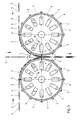
- Fig. 1 shows a schematic side view of the structure of a device for Manufacture of multi-chamber infusion bags.
- the device consists in essentially of two arranged in pairs and against each other running transport and pressure rollers 1, which are arranged so that each other a joining station 2 at the point of the smallest radial distance from one another form for connecting individual chambers 3.
- each transport and pressure roller 1 individual pockets 4, each for receiving one Serve chamber 3.
- the individual pockets 4 are formed by increased Intermediate webs 5 separated from each other.
- the individual chambers 3 are so on the transport and pressure rollers 1 that the quantity of substance to be leached containing bag part in the pocket 4 between two intermediate webs 5, while a head end 6 of each chamber 3 on the front in the direction of transport Intermediate web 5 rests.
- a handle 7 which is designed as a band-shaped carrier material is.
- a laser 8 is arranged above the joining station 2 on both sides of the handle 7 fed as an endless belt in such a way that the respective laser beams are precisely focused on the joining station 2.
- a CO 2 laser is particularly suitable for this purpose.
- a laser 8 is arranged in the interior of each transport and printing roller 1, whose respective laser beams are precisely focused on the joining station 2.
- the Intermediate webs 5 have radially extending through bores 9, through which the laser beams are focused on the joining station 2.
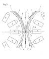
- the third embodiment shown in FIGS. 4 and 5 differs from that second according to FIGS. 2 and 3 in that each transport and Printing roller 1 several with the respective transport and printing roller 1 rotating Lasers 8 are arranged such that each intermediate web 5 has a laser 8 assigned.
- a laser 8 for the arrangement inside the transport and printing rollers 1 diode lasers are particularly suitable, preferably with a wavelength of 10 ⁇ m.
- the head ends 6 of the chambers 3 are each on the in the transport direction the transport and pressure roller 1 front intermediate web 5 stored ..
- the rotation of the two transport and pressure rollers 1 is synchronized so that two intermediate webs 5 each on the area forming the joining station 2 the smallest distance directly opposite each other, like this in particular 3 and 5 can be seen.
- the joining station 2 is simultaneously with the Chambers 3 also supplied the handle 7, which in this case as a ribbon Carrier material is formed, which via an endless belt of the joining station 2 is fed.
- FIGS. 2 to 5 are the lasers 8 arranged inside the transport and printing rollers 1.
- the laser beams can be made via through holes 9 formed in the intermediate webs 5 Focus exactly on the joining station 2.
- the handle 7 is closed on both sides at the head ends 6 of the chambers 3 Welding point provided with print marks 7a that the impinging Absorb light energy and convert it into heat. This heat becomes Welding the handle 7 with the chambers 3 used.
- welding material are in the material of the chambers 3 at least in the area of Head ends 6 existing plastic fibers and / or one on both sides in the area of Printing marks 7a made on the handle 7 coating weldable plastic used.
- the filter paper forming the filter material has at least in the Area of the head ends 6 plastic fibers by the laser beams be melted.
- the handle 7 at least in Connection area, preferably a coating of one on both sides weldable plastic material, especially polyethylene, so that too a fusion weld connection can be made here.
- the use of the laser 8 has the advantage that even at high Cycle speeds of the machine a safe and permanent connection of the individual chambers 3 with the handle 7 to multi-chamber infusion bags is possible.
Landscapes
- Engineering & Computer Science (AREA)
- Mechanical Engineering (AREA)
- Making Paper Articles (AREA)
- Lining Or Joining Of Plastics Or The Like (AREA)
Abstract
Description
- Fig. 1
- eine schematische Seitenansicht einer ersten Ausführungsform einer erfindungsgemäßen Vorrichtung;
- Fig. 2
- eine schematische Seitenansicht einer zweiten Ausführungsform einer erfindungsgemäßen Vorrichtung;
- Fig. 3
- eine vergrößerte schematische Detailansicht des Ausschnitts III gemäß Fig. 2;
- Fig. 4
- eine schematische Seitenansicht einer dritten Ausführungsform einer erfindungsgemäßen Vorrichtung und
- Fig. 5
- eine vergrößerte schematische Detailansicht des Ausschnitts V gemäß Fig. 4.
- 1
- Transport- und Druckwalze
- 2
- Fügestation
- 3
- Kammer
- 4
- Tasche
- 5
- Zwischensteg
- 6
- Kopfende
- 7
- Handhabe
- 7a
- Druckmarke
- 8
- Laser
- 9
- Durchgangsbohrung
- 10
- Pfeil
Claims (19)
- Verfahren zur Herstellung von Mehrkammer-Aufgußbeuteln für eine durch eine Aufgußflüssigkeit auszulaugende Substanz, insbesondere Tee, aus Filtermaterial, aus dem beutelartige Kammern (3) mit mindestens einem Substanzquantum gebildet werden, die mit einem Ende an einer Handhabe (7) befestigt werden,
dadurch gekennzeichnet, daß zwei Kammern (3) jeweils an eine Seite einer flächigen Handhabe (7) gelegt und über ihr Kopfende (6) mit der Handhabe (7) durch Laserschweißen verbunden werden. - Verfahren nach Anspruch 1, dadurch gekennzeichnet, daß durch das Laserschweißen die beutelartigen Kammern (3) zugleich an ihrem Kopfende (6) verschlossen werden.
- Verfahren nach Anspruch 1 oder 2, dadurch gekennzeichnet, daß die durch den Laser (8) erzeugte Lichtenergie auf den Schweißbereich fokussiert und in Wärme umgewandelt wird, die das im Filtermaterial der Kammern (3) und/oder in der Handhabe (7) enthaltene schweißbare Material erwärmt und unter Druck verschweißt.
- Verfahren nach Anspruch 3, dadurch gekennzeichnet, daß zur Umwandlung der Lichtenergie in Wärme Farbmarkierungen (7a) auf der Handhabe (7) angeordnet sind, die die Lichtenergie absorbieren.
- Verfahren nach Anspruch 3 und 4, dadurch gekennzeichnet, daß im Schweißbereich eine schweißbare Beschichtung auf der Handhabe (7) angebracht ist.,
- Verfahren nach mindestens einem der Ansprüche 1 bis 5, dadurch gekennzeichnet, daß die Handhabe (7) als zusammenhängendes Endlosband zwischen die Kammern (3) geführt wird.
- Aufgußbeutel für eine durch eine Aufgußflüssigkeit auszulaugende Substanz, insbesondere Tee, hergestellt nach dem Verfahren nach mindestens einem der Ansprüche 1 bis 6, mit zwei aus einem Filtermaterial bestehenden, jeweils mindestens ein Substanzquantum enthaltenden Kammern (3), die mit einer Handhabe (7) verbunden sind,
dadurch gekennzeichnet, daß, die Kammern (3) mit der Handhabe (7) durch Laserschweißen verbunden sind. - Aufgußbeutel nach Anspruch 7, dadurch gekennzeichnet, daß die Handhabe (7) durch Laserschweißen am Kopfende (6) der Kammern (3) befestigt ist.
- Aufgußbeutel nach Anspruch 7 und 8, dadurch gekennzeichnet, daß die Handhabe (7) als flächig mit dem Kopfende (6) der Kammern (3) laserverschweißtes Trägermaterial ausgebildet ist, das zumindest im Verschweißungsbereich mit einem schweißfähigem Kunststoffmaterial, insbesondere Polyethylen, beschichtet ist.
- Aufgußbeutel nach mindestens einem der Ansprüche 7 bis 9, dadurch gekennzeichnet, daß die Handhabe (7) im Verschweißungsbereich eine lichtabsorbierende Markierung (7a) aufweist.
- Vorrichtung zur Herstellung von Mehrkammer-Aufgußbeuteln, insbesondere zur Durchführung des Verfahrens nach mindestens einem der Ansprüche 1 bis 6, mit Transportmitteln zum Zuführen der miteinander zu verbindenden Kammern (3) zu einer Fügestation (2),
dadurch gekennzeichnet, daß die Transportmittel als zwei gegeneinander laufende Transport- und Druckwalzen (1) ausgebildet sind, über die einzelne Kammern (3) nacheinander der Fügestation (2) zuführbar sind, und gleichzeitig mit den Kammern (3) die Handhabe (7) zuführbar ist, und daß auf den Bereich der Fügestation (2) der Lichtstrahl mindestens eines Lasers (8) fokussierbar ist, über den die einzelnen Kammern (3) mit der Handhabe (7) verschweißbar und ggf. zusätzlich am Kopfende (6) verschließbar sind. - Vorrichtung nach Anspruch 11, dadurch gekennzeichnet, daß die gegeneinander laufenden Transport- und Druckwalzen (1) auf ihren jeweiligen Umfangsflächen Taschen (4) zur Aufnahme einer Kammer (3) aufweisen, wobei die Kopfenden (6) einer jeden Kammer (3) auf einem erhöhten Zwischensteg (5) zwischen den Taschen (4) gelagert sind, und daß die gegenläufige Rotationsbewegung der Transport- und Druckwalzen (1) so synchronisiert ist, daß sich jeweils zwei Zwischenstege (5) an dem die Fügestation (2) bildenden Bereich mit dem geringsten Abstand einander direkt gegenüberliegen und die Kammern und die Handhabe mit Druck miteinander verschweißbar sind.
- Vorrichtung nach mindestens einem der Ansprüche 11 und 12, dadurch gekennzeichnet, daß der mindestens eine Laser (8) so angeordnet ist, daß dessen Laserstrahl auf die Fügestation (2) fokussierbar ist.
- Vorrichtung nach mindestens einem der Ansprüche 11 und 12, dadurch gekennzeichnet, daß zwei Laser (8) im Bereich der Fügestation (2) angeordnet sind, deren Laserstrahlen von beiden Seiten der Fügestation (2) fokussierbar sind.
- Vorrichtung nach mindestens einem der Ansprüche 11 bis 14, dadurch gekennzeichnet, daß die Zwischenstege (5) sich radial erstreckende Durchgangsbohrungen (9) aufweisen, durch die der Laserstrahl wenigstens eines im Innern der Transport- und Druckwalzen (1) angeordneten Lasers (8) auf die Fügestation (2) fokussierbar ist.
- Vorrichtung nach Anspruch 15, dadurch gekennzeichnet, daß in jeder Transport- und Druckwalze (1) ein Laserstrahl (8) ortsfest auf die Fügestation (2) ausgerichtet ist.
- Vorrichtung nach Anspruch 15, dadurch gekennzeichnet, daß in jeder Transport- und Druckwalze (1) mehrere mit der jeweiligen Transport- und Druckwalze (1) umlaufende Laser (8) derart angeordnet sind, daß jedem Zwischensteg (5) jeweils ein Laser (8) zugeordnet ist.
- Vorrichtung nach Anspruch 17, dadurch gekennzeichnet, daß als Laser (8) Dioden-Laser verwendet werden.
- Vorrichtung nach mindestens einem der Ansprüche 11 bis 15, dadurch gekennzeichnet, daß der mindestens eine Laser (8) ein CO2-Laser ist.
Priority Applications (2)
| Application Number | Priority Date | Filing Date | Title |
|---|---|---|---|
| EP00107222A EP1142789B1 (de) | 2000-04-01 | 2000-04-01 | Verfahren und Vorrichtung zur Herstellung von Mehrkammer-Aufgussbeuteln |
| DE50001441T DE50001441D1 (de) | 2000-04-01 | 2000-04-01 | Verfahren und Vorrichtung zur Herstellung von Mehrkammer-Aufgussbeuteln |
Applications Claiming Priority (1)
| Application Number | Priority Date | Filing Date | Title |
|---|---|---|---|
| EP00107222A EP1142789B1 (de) | 2000-04-01 | 2000-04-01 | Verfahren und Vorrichtung zur Herstellung von Mehrkammer-Aufgussbeuteln |
Publications (2)
| Publication Number | Publication Date |
|---|---|
| EP1142789A1 true EP1142789A1 (de) | 2001-10-10 |
| EP1142789B1 EP1142789B1 (de) | 2003-03-12 |
Family
ID=8168361
Family Applications (1)
| Application Number | Title | Priority Date | Filing Date |
|---|---|---|---|
| EP00107222A Expired - Lifetime EP1142789B1 (de) | 2000-04-01 | 2000-04-01 | Verfahren und Vorrichtung zur Herstellung von Mehrkammer-Aufgussbeuteln |
Country Status (2)
| Country | Link |
|---|---|
| EP (1) | EP1142789B1 (de) |
| DE (1) | DE50001441D1 (de) |
Citations (2)
| Publication number | Priority date | Publication date | Assignee | Title |
|---|---|---|---|---|
| GB681816A (en) | 1948-07-08 | 1952-10-29 | Teepack Spezialmaschinen G M B | Improvements in folded packets |
| EP0448325A1 (de) * | 1990-03-21 | 1991-09-25 | Unilever Plc | Beutel und Verpackungsverfahren |
-
2000
- 2000-04-01 EP EP00107222A patent/EP1142789B1/de not_active Expired - Lifetime
- 2000-04-01 DE DE50001441T patent/DE50001441D1/de not_active Expired - Fee Related
Patent Citations (3)
| Publication number | Priority date | Publication date | Assignee | Title |
|---|---|---|---|---|
| GB681816A (en) | 1948-07-08 | 1952-10-29 | Teepack Spezialmaschinen G M B | Improvements in folded packets |
| EP0448325A1 (de) * | 1990-03-21 | 1991-09-25 | Unilever Plc | Beutel und Verpackungsverfahren |
| EP0448325B1 (de) | 1990-03-21 | 1993-08-11 | Unilever Plc | Beutel und Verpackungsverfahren |
Also Published As
| Publication number | Publication date |
|---|---|
| DE50001441D1 (de) | 2003-04-17 |
| EP1142789B1 (de) | 2003-03-12 |
Similar Documents
| Publication | Publication Date | Title |
|---|---|---|
| DE3401959C3 (de) | Vorrichtung zum Heißgasschweißen | |
| DE3688074T2 (de) | Ultraschallschweissvorrichtung mit kontaktflaechen. | |
| DE2410055C3 (de) | Verfahren und Vorrichtung zum Verschweißen von Bandmaterial mittels Ultraschall | |
| DE3502608C2 (de) | ||
| CH621468A5 (de) | ||
| DE102012015160B4 (de) | Vorrichtung und Verfahren zur Herstellung von Kunststoffbeuteln | |
| DE2405943C3 (de) | Heißluftsiegelvorrichtung zum Verbinden von zwei Verpackungsmaterialbahnen | |
| DE10226148A1 (de) | Vorrichtung zum Verkleben zweier Verpackungsmaterialbahnen | |
| DE2419530C3 (de) | Tubenförmiger Behälter aus einer mehrschichtigen thermoplastischen Harzschichtfolie | |
| DE2845271A1 (de) | Schweissbacke fuer verpackungsmaschinen | |
| DE2726599C2 (de) | Verfahren zur Herstellung einer Filterzigarette, Vorrichtung zur Durchführung des Verfahrens und nach diesem Verfahren hergestellte Filterzigarette | |
| LU85945A1 (de) | Vorrichtung zum selbsttaetigen aufbringen und andruecken von bahnen aus gummi oder dgl.auskleidungsmaterial auf ausgedehnte flaechen von waenden | |
| DE69804958T2 (de) | Verfahren und vorrichtung zum füllen von tuben | |
| EP1142789B1 (de) | Verfahren und Vorrichtung zur Herstellung von Mehrkammer-Aufgussbeuteln | |
| DE19837763A1 (de) | Verfahren zur Herstellung von Heißsiegel-Verpackungen und ein Werkzeug zur Durchführung des Verfahrens | |
| DE2656804C3 (de) | Verfahren zum T- oder Stumpfschweißen von Schichtkörpern mit einer Innenschicht aus thermoplastischem Schaumkunststoff | |
| DE2330500C2 (de) | Flüssigkeitsverpackung und Vorrichtung zur Herstellung dieser Verpackung | |
| DE1185045B (de) | Maschine zum Herstellen von Schlauchabschnitten mit Seitenfalten fuer Faltbeutel | |
| EP0174921A2 (de) | Verfahren zur Herstellung von Polsterungen für Skischuhe, insbesondere zur Herstellung von Innenschuhen für Skischuhe | |
| EP0374530B1 (de) | Verfahren zur Herstellung von längsnahtgeschweissten Zargen für Blechdosen und Vorrichtung zur Durchführung des Verfahrens | |
| DE2621799A1 (de) | Verfahren und vorrichtung zum trennschweissen eines kunststoffstreifens | |
| EP0453408A1 (de) | Vorrichtung zum Einschweissen eines aus zwei Teilen bestehenden Verschliessstreifens zwischen zwei thermoplastische Folien | |
| EP1164080A1 (de) | Verfahren und Vorrichtung zum kontinuierlichen Herstellen von Aufgussbeuteln sowie einen Aufgussbeutel | |
| DE19509409C2 (de) | Verfahren und Vorrichtung zum Herstellen von Tragbeuteln aus thermoplastischem Kunststoff | |
| DE2906827A1 (de) | Vorrichtung zum herstellen von beuteln |
Legal Events
| Date | Code | Title | Description |
|---|---|---|---|
| PUAI | Public reference made under article 153(3) epc to a published international application that has entered the european phase |
Free format text: ORIGINAL CODE: 0009012 |
|
| 17P | Request for examination filed |
Effective date: 20001002 |
|
| AK | Designated contracting states |
Kind code of ref document: A1 Designated state(s): AT BE CH CY DE DK ES FI FR GB GR IE IT LI LU MC NL PT SE Kind code of ref document: A1 Designated state(s): DE FR GB IT |
|
| AX | Request for extension of the european patent |
Free format text: AL;LT;LV;MK;RO;SI |
|
| 17Q | First examination report despatched |
Effective date: 20011030 |
|
| RTI1 | Title (correction) |
Free format text: METHOD AND DEVICE FOR MAKING MORE COMPARTMENTS INFUSION BAGS |
|
| GRAG | Despatch of communication of intention to grant |
Free format text: ORIGINAL CODE: EPIDOS AGRA |
|
| AKX | Designation fees paid |
Free format text: DE FR GB IT |
|
| GRAG | Despatch of communication of intention to grant |
Free format text: ORIGINAL CODE: EPIDOS AGRA |
|
| GRAH | Despatch of communication of intention to grant a patent |
Free format text: ORIGINAL CODE: EPIDOS IGRA |
|
| GRAH | Despatch of communication of intention to grant a patent |
Free format text: ORIGINAL CODE: EPIDOS IGRA |
|
| GRAA | (expected) grant |
Free format text: ORIGINAL CODE: 0009210 |
|
| AK | Designated contracting states |
Designated state(s): DE FR GB IT |
|
| PG25 | Lapsed in a contracting state [announced via postgrant information from national office to epo] |
Ref country code: IT Free format text: LAPSE BECAUSE OF FAILURE TO SUBMIT A TRANSLATION OF THE DESCRIPTION OR TO PAY THE FEE WITHIN THE PRESCRIBED TIME-LIMIT;WARNING: LAPSES OF ITALIAN PATENTS WITH EFFECTIVE DATE BEFORE 2007 MAY HAVE OCCURRED AT ANY TIME BEFORE 2007. THE CORRECT EFFECTIVE DATE MAY BE DIFFERENT FROM THE ONE RECORDED. Effective date: 20030312 Ref country code: GB Free format text: LAPSE BECAUSE OF FAILURE TO SUBMIT A TRANSLATION OF THE DESCRIPTION OR TO PAY THE FEE WITHIN THE PRESCRIBED TIME-LIMIT Effective date: 20030312 Ref country code: FR Free format text: LAPSE BECAUSE OF FAILURE TO SUBMIT A TRANSLATION OF THE DESCRIPTION OR TO PAY THE FEE WITHIN THE PRESCRIBED TIME-LIMIT Effective date: 20030312 |
|
| REG | Reference to a national code |
Ref country code: GB Ref legal event code: FG4D Free format text: NOT ENGLISH |
|
| REF | Corresponds to: |
Ref document number: 50001441 Country of ref document: DE Date of ref document: 20030417 Kind code of ref document: P |
|
| PGFP | Annual fee paid to national office [announced via postgrant information from national office to epo] |
Ref country code: DE Payment date: 20030618 Year of fee payment: 4 |
|
| GBV | Gb: ep patent (uk) treated as always having been void in accordance with gb section 77(7)/1977 [no translation filed] |
Effective date: 20030312 |
|
| PLBE | No opposition filed within time limit |
Free format text: ORIGINAL CODE: 0009261 |
|
| STAA | Information on the status of an ep patent application or granted ep patent |
Free format text: STATUS: NO OPPOSITION FILED WITHIN TIME LIMIT |
|
| EN | Fr: translation not filed | ||
| 26N | No opposition filed |
Effective date: 20031215 |
|
| PG25 | Lapsed in a contracting state [announced via postgrant information from national office to epo] |
Ref country code: DE Free format text: LAPSE BECAUSE OF NON-PAYMENT OF DUE FEES Effective date: 20041103 |