EP1144919B1 - Wasserheizer mit mehrparameterreglung - Google Patents
Wasserheizer mit mehrparameterreglung Download PDFInfo
- Publication number
- EP1144919B1 EP1144919B1 EP99936761A EP99936761A EP1144919B1 EP 1144919 B1 EP1144919 B1 EP 1144919B1 EP 99936761 A EP99936761 A EP 99936761A EP 99936761 A EP99936761 A EP 99936761A EP 1144919 B1 EP1144919 B1 EP 1144919B1
- Authority
- EP
- European Patent Office
- Prior art keywords
- water
- heater
- temperature
- level
- water heater
- Prior art date
- Legal status (The legal status is an assumption and is not a legal conclusion. Google has not performed a legal analysis and makes no representation as to the accuracy of the status listed.)
- Expired - Lifetime
Links
- XLYOFNOQVPJJNP-UHFFFAOYSA-N water Substances O XLYOFNOQVPJJNP-UHFFFAOYSA-N 0.000 title claims abstract description 209
- 238000010438 heat treatment Methods 0.000 claims abstract description 33
- 230000003750 conditioning effect Effects 0.000 claims abstract description 28
- 238000001556 precipitation Methods 0.000 claims abstract description 11
- 230000001965 increasing effect Effects 0.000 claims abstract description 5
- 239000008233 hard water Substances 0.000 claims description 3
- 238000009825 accumulation Methods 0.000 claims description 2
- 239000013505 freshwater Substances 0.000 claims description 2
- 230000006698 induction Effects 0.000 claims description 2
- 230000001939 inductive effect Effects 0.000 claims description 2
- 230000001143 conditioned effect Effects 0.000 abstract description 4
- 238000009835 boiling Methods 0.000 description 15
- 238000000034 method Methods 0.000 description 7
- VTYYLEPIZMXCLO-UHFFFAOYSA-L Calcium carbonate Chemical compound [Ca+2].[O-]C([O-])=O VTYYLEPIZMXCLO-UHFFFAOYSA-L 0.000 description 6
- 239000003990 capacitor Substances 0.000 description 5
- 230000003287 optical effect Effects 0.000 description 5
- 150000003839 salts Chemical class 0.000 description 5
- 235000013361 beverage Nutrition 0.000 description 4
- 230000009467 reduction Effects 0.000 description 4
- 230000004913 activation Effects 0.000 description 3
- 229910000019 calcium carbonate Inorganic materials 0.000 description 3
- 238000012423 maintenance Methods 0.000 description 3
- 239000002244 precipitate Substances 0.000 description 3
- 230000008569 process Effects 0.000 description 3
- 230000001276 controlling effect Effects 0.000 description 2
- 230000000694 effects Effects 0.000 description 2
- 230000005670 electromagnetic radiation Effects 0.000 description 2
- 238000013021 overheating Methods 0.000 description 2
- 230000001105 regulatory effect Effects 0.000 description 2
- 238000010977 unit operation Methods 0.000 description 2
- HLYCTXRRGDDBOW-UHFFFAOYSA-N 2-methylpiperazine-1-carbodithioic acid Chemical compound CC1CNCCN1C(S)=S HLYCTXRRGDDBOW-UHFFFAOYSA-N 0.000 description 1
- OYPRJOBELJOOCE-UHFFFAOYSA-N Calcium Chemical compound [Ca] OYPRJOBELJOOCE-UHFFFAOYSA-N 0.000 description 1
- 235000008733 Citrus aurantifolia Nutrition 0.000 description 1
- 229920000388 Polyphosphate Polymers 0.000 description 1
- 235000011941 Tilia x europaea Nutrition 0.000 description 1
- 230000004075 alteration Effects 0.000 description 1
- 230000004888 barrier function Effects 0.000 description 1
- 230000009286 beneficial effect Effects 0.000 description 1
- 230000033228 biological regulation Effects 0.000 description 1
- 230000015572 biosynthetic process Effects 0.000 description 1
- 229910052791 calcium Inorganic materials 0.000 description 1
- 239000011575 calcium Substances 0.000 description 1
- 230000008859 change Effects 0.000 description 1
- 239000013626 chemical specie Substances 0.000 description 1
- 238000004140 cleaning Methods 0.000 description 1
- 238000001816 cooling Methods 0.000 description 1
- 239000013078 crystal Substances 0.000 description 1
- 230000008021 deposition Effects 0.000 description 1
- 238000010586 diagram Methods 0.000 description 1
- 230000035622 drinking Effects 0.000 description 1
- 239000003651 drinking water Substances 0.000 description 1
- 235000020188 drinking water Nutrition 0.000 description 1
- 230000005672 electromagnetic field Effects 0.000 description 1
- 238000009499 grossing Methods 0.000 description 1
- 230000036541 health Effects 0.000 description 1
- 238000005286 illumination Methods 0.000 description 1
- 230000036039 immunity Effects 0.000 description 1
- 150000002500 ions Chemical class 0.000 description 1
- 230000001788 irregular Effects 0.000 description 1
- 239000004571 lime Substances 0.000 description 1
- 239000007788 liquid Substances 0.000 description 1
- 230000004048 modification Effects 0.000 description 1
- 238000012986 modification Methods 0.000 description 1
- 229910052754 neon Inorganic materials 0.000 description 1
- GKAOGPIIYCISHV-UHFFFAOYSA-N neon atom Chemical compound [Ne] GKAOGPIIYCISHV-UHFFFAOYSA-N 0.000 description 1
- 239000001205 polyphosphate Substances 0.000 description 1
- 235000011176 polyphosphates Nutrition 0.000 description 1
- 230000002265 prevention Effects 0.000 description 1
- 230000000630 rising effect Effects 0.000 description 1
- 239000003352 sequestering agent Substances 0.000 description 1
- 235000013619 trace mineral Nutrition 0.000 description 1
- 239000011573 trace mineral Substances 0.000 description 1
- 230000000007 visual effect Effects 0.000 description 1
- 238000004804 winding Methods 0.000 description 1
Images


Classifications
-
- F—MECHANICAL ENGINEERING; LIGHTING; HEATING; WEAPONS; BLASTING
- F24—HEATING; RANGES; VENTILATING
- F24H—FLUID HEATERS, e.g. WATER OR AIR HEATERS, HAVING HEAT-GENERATING MEANS, e.g. HEAT PUMPS, IN GENERAL
- F24H9/00—Details
- F24H9/0005—Details for water heaters
- F24H9/0042—Cleaning arrangements
-
- F—MECHANICAL ENGINEERING; LIGHTING; HEATING; WEAPONS; BLASTING
- F24—HEATING; RANGES; VENTILATING
- F24D—DOMESTIC- OR SPACE-HEATING SYSTEMS, e.g. CENTRAL HEATING SYSTEMS; DOMESTIC HOT-WATER SUPPLY SYSTEMS; ELEMENTS OR COMPONENTS THEREFOR
- F24D19/00—Details
- F24D19/0092—Devices for preventing or removing corrosion, slime or scale
-
- F—MECHANICAL ENGINEERING; LIGHTING; HEATING; WEAPONS; BLASTING
- F24—HEATING; RANGES; VENTILATING
- F24D—DOMESTIC- OR SPACE-HEATING SYSTEMS, e.g. CENTRAL HEATING SYSTEMS; DOMESTIC HOT-WATER SUPPLY SYSTEMS; ELEMENTS OR COMPONENTS THEREFOR
- F24D17/00—Domestic hot-water supply systems
Definitions
- the present invention relates to water heaters, particularly to those commonly known as vented water heaters. More particularly, the invention relates to control of parameters such as water temperature, water level and limescale precipitation.
- Water heaters typically incorporate a vent either to allow surplus liquid to run off or to prevent excess vapour pressure from the heated water causing the vessel holding the water to rupture.
- Conventional vented and non-vented heaters are furnished with means to control two parameters, namely the water level within a vessel for containing the water to be heated and the temperature of that water By implementing control over these parameters, water heaters can be provided from which small quantities of hot water can be removed at irregular intervals, for example, to prepare beverages. Replacement cold water is subsequently admitted to restore the level to its desired position but alters the temperature of the water in the vessel. Heating is then applied to counteract the cooling effect of the introduced cold water, to restore the temperature to a predetermined value.
- Mechanical control of the level can be achieved using various means such as a float operated valve.
- Electro-mechanical means such as a rod, capillary or bimetallic disk type thermostat may be used for level and temperature control. More recently, electronic circuits controlling, via suitable electronic sensing devices, the temperature, water level or both are used.
- the present invention has as its object, the provision of such a water heater.
- the object of the present invention is to provide an improved water heater which includes both level and temperature control of water held in a heating vessel for subsequent dispensing. To maintain the efficiency of the heater, prevention or reduction of limescale build-up within the heater is required.
- the present invention provides a water heater having a vessel for holding water to be heated, a heating element, at least one temperature sensor, one or more level sensors and a control circuit, characterised in that the water heater includes means for actively conditioning water to be heated, said means comprising an induction coil or closed loop antenna coiled about a water inlet pipe, said means being operable via the control circuit, to prevent or reduce the precipitation of limescale from the water, by inducing a conditioning signal in the water, so as to reduce limescale build-up within the heater, thereby increasing its efficiency and prolonging its useful life.
- the conditioning signal comprises electromagnetic energy, the frequency and intensity of which is variable.
- the electromagnetic energy alters the characteristics of "hard water” to reduce scale precipitation from the water and accumulation of that scale on hot surfaces within the heater.
- the conditioning signal is intensified for greater volumes of water drawn through the inlet pipe.
- the conditioning signal generated cyclically sweeps through a range of frequencies.
- the frequency sweep is non-continuous in that pre-selected frequencies are applied to the water for longer periods than other frequencies.
- the control circuit is housed within the water heater and includes means for correlating level and temperature signals so as to maintain substantially a pre-selected volume of water at a predetermined temperature. Release of water from the heater may be restricted until the predetermined temperature is achieved.
- a preferred embodiment of water heater has a vessel for holding water to be heated, a heating element, a first temperature sensor located adjacent the heating element, a second temperature sensor at or towards the top of the vessel to detect steam, a "half-full" level sensor, a “full” level sensor and a control circuit wherein the water heater includes a coil or antenna connected to the control circuit which induces through the loop or antenna a conditioning signal in water drawn through an inlet pipe, the conditioning signal preventing or reducing the precipitation of limescale from the water,
- the control circuit being governed by a microprocessor which reads sensor signals from the level and temperature sensors to control water temperature and level within the heater, the conditioning means being enabled when fresh water is introduced into the heater.
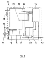
- FIG. I shows a heater, generally referenced 10, comprising a vessel 11 in which water is heated by a heating element 12.
- the vessel is connected by inlet pipe 13 to a water supply. Control of the rate of inflow of water is by means of inlet solenoid valve 14 which is governed by the control circuit 15.
- the heater 10 also comprises an outlet pipe 16, allowing heated water to be drawn off to prepare beverages and through which flow is manually regulated by means of outlet valve 17.
- the vessel 11 further comprises a vent 18 through which excess pressure created by the increasing vapour pressure of the water as it is heated, is released.
- a level sensor 19 detects when the water level has reached a certain predetermined height and when it has, causes the inlet solenoid valve 14 to close off the water inlet pipe 13.
- a further sensor 20 is positioned to detect whether vessel 11 is less than half full. In such a situation it causes, via the control circuit 15, the heating element 12 to be switched off. In this way, the risk of over heating the element 12, due to an insufficient volume of water being present is reduced.
- the heating element 12 is further controlled by means of the temperature control sensor 21, which operates such that when the water temperature drops below a pre-set level, the element 12 is activated. Similarly when the temperature exceeds a further pre-set level then power to the element 12 is switched off, thus causing the water temperature to fall. Boiling of the water is detected by steam thermistor 22, which is positioned above the maximum pre-set water level and which measures the temperature of the vapour above the water.
- the circuit is also equipped with a boil interval timer such that, should heating not occur for a defined period, a boil sequence is initiated.
- the control circuit 15 may also be designed such that the power supply to the heating element is varied as a function of the difference between two pre-set temperature levels, and additionally or alternatively to take into account the rate of heating for a given value of power supplied. Such a facility would be able to maintain a relatively constant water temperature and also optimise power consumption.
- the heater 10 further comprises a closed loop antennae 23 which imparts to the water being admitted to the vessel 11 by inlet point 13, electromagnetic radiation generated in circuit 15.
- electromagnetic radiation can reduce deposition of limescale (chiefly calcium carbonate), particularly around heating elements, by altering the solution characteristics of the dissolved salts such that precipitation is reduced.
- Typical frequencies generated by the circuit 15 to prevent scaling, all with a 50% duty cycle, are 1.5, 2.0, 2.5, 3.0, and 4.0 kHz. In use this range of frequencies sweeps sequentially backwards and forwards at a rate of approximately 16 milliseconds per frequency Operation of the frequency generator can take place either permanently, whilst the heater is in operation, or when the-inlet solenoid valve is open.
- the circuit is further equipped to deactivate the frequency generation should a critical fault occur.
- the heater can also be provided with a start up sequence of events.
- water is admitted via inlet pipe 13.
- the heater element 12 is activated along with a light-emitting diode (LED) display to indicate this to the user.
- the inflow of water is continued until the full level sensor 19 is activated, causing the inlet solenoid valve 14 to be closed
- a boil timer is initiated. Should the water then reach a temperature just below the boiling point within a certain pre-set time, the circuit 15 will cause the power to the heating element 12 to be switched off.
- the steam thermistor 22 assesses the steam temperature. Once this sensor detects a rapid rise in the steam temperature, this is taken as an indication that the water is boiling and the heating element is then switched off.
- the commissioning sequence is then at an end, and the water heater enters its idle stage.
- An LED display then indicates to the user that the water is ready to be drawn off Typically, the circuit will be designed such that until the heater has undergone this commissioning sequence, the indicator will not be illuminated. In normal usage, the light will be on when the temperature of the water is above the minimum usable temperature of 92C.
- the circuit 15 will activate the heater. Conversely, should the temperature exceed the threshold, the heater will be deactivated. Typically a small amount of hysteresis will be introduced. In this manner the heater will not be switched on and off in rapid succession.
- the circuit 15 mounted on a printed circuit board (PCB) detects, whether water has been drawn off during a certain defined period, perhaps by means of a timer connected to the inlet solenoid valve 14. If no water has been drawn off, then the heater can enter a standby phase, in which the water temperature is maintained at the calibrated or fixed standby reference. This can again be set at 98C plus or minus 1C, or whatever temperature is desired or permitted by regulation.
- PCB printed circuit board
- Certain safety features can also be introduced into the heater to minimise the risk of overheating of the element, or boil off of the water, and also to prevent the water being maintained at too low a temperature which can introduce health risks. For example, if the half level switch is deactivated whilst the full level switch is still active, and indicating that maximum normal level of water is present, then this will result in the heater element being switched off and the inlet solenoid valve being closed, preventing further water from entering the vessel. Also, a timer can operate, to monitor the length of time that the inlet valve is open, and if a pre-set time is exceeded, cause shutdown of the heater When other faults occur, the heater can continue to function, but at a less optimum level.
- non-critical faults are indicated to the user by, for example, an LED light flashing.
- An example of a non-critical fault is failure to detect boiling during the commissioning sequence. In this case water temperatures are maintained using non-calibrated settings During non-critical fault conditions, boiling is terminated either by the water temperature reaching a pre-set level, or by the boil timer expiring.
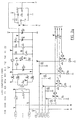
- control circuit 15 comprises a power supply, a power circuit for the heating element and inlet solenoid valve of the water heater under control of a valve drive circuit and a signal processor for reading sensor-supplied signals and interpreting those signals according to pre-programmed criteria.
- Mains power is supplied across mains supply connectors (CN5-1, CN6-1) to a mains transformer (TX1, TT1808) via a fuse (F1, 200mA).
- a varistor (R30, 265VRMS) is provided to protect the power supply from mains borne transients
- a 12 volt ac output from the transformer (TX1) is rectified through a diode bridge (D19 to D22, IN4007) and regulated through a circuit centred about a standard regulator configuration including a switching transistor (T8, BC817) and zener diode (Z2, 5V1, BZV55C) to 5 volts for the logic circuitry.
- the voltage across a base connected resistor (R32) causes one of a pair of Darlington coupled transistors (T9, BC847) to turn “ON” turning “OFF” the other of the coupled transistors (T10, BC847) and allowing an accumulating capacitor (C16) to charge from the regulator output via a series coupled resistor R34.
- This provides the required reset signal to the microcontroller (IC1, 68HC705P6ACDW).
- a diode (D23, IN4007) allows rapid discharge of the capacitor (C16) during power-down. Smoothing capacitors (C15, C17) are provided to eliminate supply ripple.
- the microcontroller (IC1) performs control functions for water heating and temperature maintenance, water filling, LED status indication and water treatment.
- a crystal (Y1, 4MHz) and associated capacitors (C1, C2) form part of an oscillator circuit which operates at an overall frequency of 4MHz.
- a bank of unit status LEDs are fed through LED driver circuits and fed via a connector (CN4-12CN4-5).
- the LED indicators are mounted on a separate PCB and are configured to operate in common anode mode from a rectified but unregulated 12 volt feed taken from the secondary winding of the transformer (TX1).
- Switching of the LEDs is performed under the control of the microcontroller IC1 via switching transistors (T1 to T4, BC847) provided in an emitter follower configuration in the driver circuits. This configuration prevents variations in the unregulated supply from affecting the LED current and hence the intensity of the LEDs.
- Resistors (R19, R21, R23, R25) set the LED operating current at approximately 9mA.
- a relay (RL1, GHP-1111P- 12VDC) and its associated switching transistor (T6, BC817) control power to the heating element (via connectors CN7-1, CN8-1) again under control of the microcontroller (IC1).
- a snubber network (C18, R35) is formed across the relay contacts to reduce switching interference.
- the voltage developed across a ground connected resistor (R51) can be used by the microcontroller (IC1) to measure the relay current.
- An optical coupler (IC5, TLP3062) and associated components (transistors T7, BC847 and T12, BC857) provide water inlet solenoid valve control. As the first solenoid driver transistor (T7) is turned “ON”, so the second driver transistor (T12) is driven “ON” supplying current to the optical coupler IC5 allowing current to flow through to the valve connector (CN10-1, CN9-1).
- a snubber network (C19, R44) is provided to help reduce switching interference.
- the optical coupler circuit includes a detector that only allows switching to occur at the mains waveform zero crossing point.
- Input signals from the full and half full float switches across float signal connectors (CN1-5 and CN1-10, CN1-4 and CN1-3) are presented to the microcontroller (IC1) via series resistors (R2, R4)
- the active state for the float switches is normally closed. In this condition, current flows to ground (GND) from optical coupler (IC5) via series resistor (R39) for the full float switch and via a resistor (R45), coupled to the 12 volt rail, for the half-full float switch.
- the full float switch completes the current path for the water solenoid valve optical coupler (IC5). This ensures that a failure of the microcontroller (IC1) will not cause an over-fill condition.
- the 12 volt rail coupled resistor (R45) provides a whetting current when the half-full float switch closes.
- Steering diodes (D9 and D10, IN4007) provide a path to ground (GND) via pull up resistors (R3, R5) on the full float and half-full float switch circuits, respectively.
- This arrangement allows the microcontroller (IC1) to detect float switch activation at a low logic level (at PC0 and PC1).
- the steam thermistor input is presented also across a connector (CN1-6, CN1-7) for feeding data to the microcontroller (IC1).
- the thermistor and a resistor (R11) tied to the 5 volt rail together form a potential divider to provide a control voltage to one part of a conditioning operational amplifier (IC3A, LM2904).
- the gain of the thermistor signal is increased here and the voltage span is reduced to allow the microcontroller (IC1) to monitor (at PC5/AN1) a relatively small temperature range.
- the water thermistor input is taken across its respective connector (CN1-8, CN1-9) and is conditioned in an identical way to the second part of the conditioning operational amplifier (IC3B) but includes a switching transistor (T11, BC847) in the circuit.
- two temperature ranges may be measured by shorting out a resistor (R43) by switching the transistor (T11) via the microcontroller (IC1, at PA7). Similarly, the transistor (T11 can be turned “OFF” to provide extended water temperature coverage.
- the outputs of both parts of the conditioning operational amplifier (IC3A, IC3B) are fed via protection resistors (R48, R49) to ADC channels 0 and 1 (PC6/AN0, PC5/AN1) on the microcontroller (IC1).
- Capacitors (C7, C8, C9, C10) are provided to help increase noise immunity.
- the water treatment driver circuitry comprises a switching transistor (T5, BC817) and associated components.
- a current is unlimited by a protection resistor (R27) to approximately 70mA.
- the driver of the circuit is controlled by the microcontroller (IC1) which generates a variable frequency square-wave output.
- the resulting output current flows through a wire loop provided across the descaler connector (CN1-1, CN1-2) to provide conditioning of the incoming water flow.
- the frequency and amplitude of the electromagnetic wave induced in the wire loop is controlled by the microcontroller (IC1, at TCMP).
- the microcontroller (IC1) is provided with pre-selected program instructions to read, interpret and act upon level and temperature parameters.
- the programming includes initialisation procedures and fault condition contingencies. The overall operation of the programming is indicated below:
- the water heater always assumes that the tank is empty whenever the unit is powered up. If the tank is not empty but full then the inlet solenoid for valve is deactivated.
- the unit For water boil, the unit normally expects to see a rapid rise in steam temperature to indicate the start of a boiling condition. Once boiling has been detected the unit switches off the heater. Water thermistor calibration takes place after expiry of the boil timer.
- the above event indicates the end of the initialisation sequence.
- the water heater enters the idle state.
- the ready LED illuminates indicating that the unit is ready for use.
- the water tank thermistor is calibrated to provide the tank temperature maintenance points for both normal and standby operation. Failure to detect boiling shall result in a non-critical fault condition being generated and termination of the initialisation sequence.
- the normal and standby water temperatures are maintained using a non-calibrated setting
- a boil timer shall operate during this condition. If allowed to expire the unit terminates boiling.
- the normal and standby water temperatures are maintained using a non-calibrated setting Boiling is terminated when the water temperature reaches a pre-set boiling point.
- the tank fills from empty and when the water level has risen the required amount to activate the half full level float switch, the half full LED illuminates The half full LED extinguishes as water is drawn from the unit below the level of the half full level float switch. Activation of the full level float switch without corresponding activation of the half level float switch shall cause the unit to enter a critical fault condition.
- the water level is expected to rise and activate the full level float switch at which time the full level LED illuminates.
- the water inlet solenoid is immediately deactivated.
- a boil sequence is initiated if the unit was in standby mode when water was requested.
- the water inlet solenoid activates when water is drawn from the unit and the full level LED extinguishes indicating that the tank in no longer full.
- the water boil sequence is subsequently initiated on expiry of the boil duration timer.
- the unit enters its standby mode if no water has been drawn off for a pre-selected period of time. De-activation of the half full level float switch while the full level float switch is activated shall cause the unit to enter a critical fault condition.
- a water boil sequence in progress terminates when water is drawn from the unit.
- the unit enters normal operation when the normally active full level float switch is deactivated.
- the water fill timer monitors all water fill activities and if allowed to expire, causes the unit to enter a critical fault condition.
- the timer setting is selected to be sufficiently long in duration to avoid “timing out” under normal use.
- the unit On expiry of the boil interval timer the unit initiates a boil sequence. Operation is similar to that used during unit commissioning with the exception that no check is made for the water level being half full.
- the water tank temperature is maintained at the calibrated or fixed working reference. A small amount of hysteresis is provided to prevent rapid heater switching. Where the water thermistor has been calibrated the maintained temperature is 98 +/- 1 Centigrade. The heater is activated when the water tank temperature drops below the low threshold. The heater is deactivated when the water tank temperature rises above the high threshold.
- the water tank temperature is maintained at the calibrated or fixed standby reference. A small amount of hysteresis is again provided to prevent rapid heater switching. Where the water thermistor has been calibrated the maintained temperature is 98 +/- 1 Centigrade. The heater is activated when the water tank temperature drops below the low threshold The heater is deactivated when the water tank temperature rises above the high threshold.
- Indications that the unit is ready for use or near ready are provided by panel front mounted LEDs.
- the "READY" LED does not illuminate until the unit has completed the initialisation procedure.
- the "READY" LED illuminates when the water tank is above the minimum useable temperature of 92 and extinguishes when the water tank drops below the minimum useable temperature.
- the water conditioning circuit is active during normal unit operation but is deactivated during a critical fault condition.
- the proposed control is an electronic circuit that combines the temperature and level control functions with an electronic scale conditioning device that can be incorporated into the water heater thus obviating the need for a number of separate devices.
- the sensor detects whether the water temperature is below its pre-set value. If it is a switching means is enabled that provides electrical power to the heating means and hence raising the water temperature. When the sensor detects the pre-set temperature has been reached the switching means is disabled thus interrupting the electrical supply to the heating means and thus preventing any further temperature rise.
- the sensor positioned at the "full” level will detect this and provide a signal to the control circuit. This signal will enable a switching means to provide power to a flow control device and hence allow water to enter the heater from the water supply to replenish the heater.
- the signal to the circuit will be interrupted hence de-energising the flow control device, stopping the inlet water flow and consequently any further rise in water level within the heater.
- a further sensor may act as a "low” level sensor to prevent the heating means being energised should the water level be at a level where the heating means was not immersed
- sensors may be incorporated at differing levels to give signals of varying degrees of fill level up to the "full" level, signals from these sensors can be used to switch visual indicators (typically an LED or neon) of the level of fill achieved
- a range of electromagnetic waves of varying frequency are generated within the control circuitry and are imparted to the water supply by a closed loop antenna, the antenna being coiled around the inlet pipe of the water heater such that water flowing into the heater is conditioned.
- Application of the electromagnetic fields has been shown the alter the characteristics of the "hardness salts" such that they do not precipitate out of the water and adhere to hot surfaces within the heater
- the control circuitry may also include safeguards to ensure the heating means is not energised unless a predetermined water level has been achieved; user selection of differing control temperatures; other indications of water heater status e.g. mains power on, correct storage temperature has been achieved, scale conditioning is operating, etc.
- Temperature control, level control and scale conditioning are achieved by using one control circuit rather than several discrete devices.
- Scale conditioning does not remove the hardness salts from the water thus retaining beneficial trace elements.
- Water remains suitable for drinking purposes making this type of control especially suitable for use in water heaters for dispensing hot water for beverage making.
Landscapes
- Engineering & Computer Science (AREA)
- General Engineering & Computer Science (AREA)
- Chemical & Material Sciences (AREA)
- Thermal Sciences (AREA)
- Combustion & Propulsion (AREA)
- Mechanical Engineering (AREA)
- Physics & Mathematics (AREA)
- Cookers (AREA)
- Control Of Resistance Heating (AREA)
- Farming Of Fish And Shellfish (AREA)
- Control Of Temperature (AREA)
- Instantaneous Water Boilers, Portable Hot-Water Supply Apparatuses, And Control Of Portable Hot-Water Supply Apparatuses (AREA)
- General Induction Heating (AREA)
- Heat-Pump Type And Storage Water Heaters (AREA)
Claims (8)
- Warmwasserbereiter (10) mit einem Gefäß (11) zur Aufnahme des zu erhitzenden Wassers, einem Heizelement (12), mindestens einem Temperaturfühler (21,22), einem oder mehreren Füllstandsfühlern (19,20) und einem Steuerkreis (15), dadurch gekennzeichnet, dass der Warmwasserbereiter (10) ein Mittel (23) zur aktiven Aufbereitung des zu erhitzenden Wassers hat, wobei das Mittel eine Induktionsspule oder eine Antenne mit geschlossenem Regelkreis (23) aufweist, die um ein Wasserzulaufrohr (13) gewickelt ist, wobei das Mittel (23) durch den Steuerkreis (15) betrieben werden kann, um die Präzipitation von Kesselstein aus dem Wasser dadurch zu verhindern oder zu verringern, dass im Wasser ein Aufbereitungssignal induziert wird, das die Akkumulation von Kesselstein im Warmwasserbereiter (10) reduziert, wodurch dessen Effizienz und Lebensdauer erhöht werden.
- Warmwasserbereiter nach Anspruch 1, wobei das Aufbereitungssignal aus elektromagnetischer Energie besteht, deren Frequenz und Intensität variieren.
- Warmwasserbereiter nach Anspruch 2, wobei die elektromagnetische Energie die Eigenschaften des "harten Wassers" verändert, um die Präzipitation von Kesselstein aus dem Wasser und die Akkumulation von Kesselstein auf heißen Flächen des Warmwasserbereiters zu reduzieren.
- Warmwasserbereiter nach Anspruch 1 oder 2, wobei das Aufbereitungssignal für größere durch das Wasserzulaufrohr (13) einfließende Wasservolumen verstärkt wird.
- Warmwasserbereiter nach einem der Ansprüche 1 bis 4, wobei das erzeugte Aufbereitungssignal einen Frequenzbereich zyklisch durchläuft.
- Warmwasserbereiter nach Anspruch 5, wobei der Frequenzdurchlauf unstetig ist, da vorgewählte Frequenzen über längere Zeitintervalle auf das Wasser angelegt werden als andere Frequenzen.
- Warmwasserbereiter nach einem der vorhergehenden Ansprüche, wobei der Steuerkreis (15) im Inneren des Warmwasserbereiters angeordnet ist und Mittel zur Korrelation von Füllstands- und Temperatursignalen aufweist, um im Wesentlichen ein vorgewähltes Wasservolumen mit einer vorgegebenen Temperatur aufrechtzuerhalten, wobei der Wasserabfluss beschränkt bleibt, bis eine vorgegebene Temperatur erreicht worden ist.
- Warmwasserbereiter nach Anspruch 1, wobei der Warmwasserbereiter (10) Folgendes aufweist: ein Gefäß (11) zur Aufnahme des zu erhitzenden Wassers, ein Heizelement (12), einen dem Heizelement (12) benachbarten ersten Temperaturfühler (21), einen am oder nahe dem oberen Ende des Gefäßes (11) angeordneten zweiten Temperaturfühler (22) zum Detektieren von Dampf, einen Fühler (20) für den Füllstand "halbvoll", einen Fühler (19) für den Füllstand "voll" und einen Steuerkreis (15), wobei der Warmwasserbereiter (10) eine Spule oder Antenne (23) aufweist, die mit dem Steuerkreis (15) verbunden ist, der durch die Schleife oder Antenne (23) in dem durch ein Wasserzulaufrohr (13) einfließenden Wasser ein Aufbereitungssignal induziert, wobei das Aufbereitungssignal die Präzipitation von Kesselstein aus dem Wasser verhindert oder vermindert und der Steuerkreis (15) durch einen Mikroprozessor geregelt wird, der Fühlersignale der Füllstands- und Temperaturfühler abliest, um Wassertemperatur und Füllstand im Warmwasserbereiter zu steuern, wobei das Aufbereitungsmittel aktiviert wird, wenn frisches Wasser in den Warmwasserbereiter geleitet wird.
Applications Claiming Priority (5)
| Application Number | Priority Date | Filing Date | Title |
|---|---|---|---|
| GB9816366 | 1998-07-28 | ||
| GBGB9816366.0A GB9816366D0 (en) | 1998-07-28 | 1998-07-28 | Improvements in combined temperature level and limescale reduction control devices for water heaters |
| GBGB9825441.0A GB9825441D0 (en) | 1998-11-21 | 1998-11-21 | Improvements in combined temperature level and limescale reduction control devies for water heaters |
| GB9825441 | 1998-11-21 | ||
| PCT/GB1999/002253 WO2000006956A2 (en) | 1998-07-28 | 1999-07-28 | Water heater having multi-parameter control |
Publications (3)
| Publication Number | Publication Date |
|---|---|
| EP1144919A2 EP1144919A2 (de) | 2001-10-17 |
| EP1144919A3 EP1144919A3 (de) | 2004-04-28 |
| EP1144919B1 true EP1144919B1 (de) | 2004-05-19 |
Family
ID=26314128
Family Applications (1)
| Application Number | Title | Priority Date | Filing Date |
|---|---|---|---|
| EP99936761A Expired - Lifetime EP1144919B1 (de) | 1998-07-28 | 1999-07-28 | Wasserheizer mit mehrparameterreglung |
Country Status (7)
| Country | Link |
|---|---|
| EP (1) | EP1144919B1 (de) |
| AT (1) | ATE267368T1 (de) |
| AU (1) | AU747152B2 (de) |
| DE (1) | DE69917488D1 (de) |
| GB (1) | GB2340213A (de) |
| NZ (1) | NZ510100A (de) |
| WO (1) | WO2000006956A2 (de) |
Cited By (1)
| Publication number | Priority date | Publication date | Assignee | Title |
|---|---|---|---|---|
| WO2023118858A1 (en) * | 2021-12-22 | 2023-06-29 | Jemella Limited | Thermal control apparatus and method |
Families Citing this family (4)
| Publication number | Priority date | Publication date | Assignee | Title |
|---|---|---|---|---|
| NL2006802C2 (nl) * | 2011-05-18 | 2012-11-20 | Stichting Wetsus Ct Excellence Sustainable Water Technology | Gecombineerd sensor-actuator systeem en werkwijze voor het detecteren en/of bestrijden van aanslag op een oppervlak. |
| EP3892934B1 (de) | 2020-04-09 | 2025-05-07 | Eccotemp Systems, LLC | Verbesserter tankloser wassererhitzer |
| US11852381B2 (en) | 2020-04-09 | 2023-12-26 | Eccotemp Systems, LLC | Water heater device and method of use |
| US11448424B2 (en) | 2020-04-09 | 2022-09-20 | Eccotemp Systems, LLC | Tankless water heater with display and electronic control |
Family Cites Families (8)
| Publication number | Priority date | Publication date | Assignee | Title |
|---|---|---|---|---|
| US4406794A (en) * | 1979-02-05 | 1983-09-27 | Brigante Miguel F | External sludge collector for boiler bottom blowdown and automatic blowdown control initiated by conductivity probe within the boiler and method |
| HUT57678A (en) * | 1987-12-27 | 1991-12-30 | Zoltan Gyoergy Horvath | Process and equipment for increasing the efficiency of magnetic liquid treating devices, particularly water treating devices |
| DE3912498A1 (de) * | 1989-04-15 | 1990-10-18 | Andreas Uebele | Vorrichtung zur energetischen beeinflussung einer fluessigkeit |
| ATE101382T1 (de) * | 1990-06-05 | 1994-02-15 | Schulte Hartmut Dipl Ing | Verfahren und vorrichtung zur behandlung von wasser mit einem elekro-magnetischen feld. |
| CH682149A5 (de) * | 1990-11-26 | 1993-07-30 | Aquasal Kalkschutzanlagen Ag | |
| GB9117152D0 (en) * | 1991-08-07 | 1991-09-25 | Heatrae Sadia Heating Ltd | Heater for liquid |
| DE4314969A1 (de) * | 1993-05-06 | 1993-12-09 | Schober Elektronik Gmbh | Wasserenthärtung in wasserverarbeitenden Elektrogeräten |
| IT234849Y1 (it) * | 1994-09-26 | 2000-03-20 | Etairoi Holding Sa | Apparecchio generatore di vapore per uso domestico, in particolare per lavori di pulizia |
-
1999
- 1999-07-28 AT AT99936761T patent/ATE267368T1/de not_active IP Right Cessation
- 1999-07-28 GB GB9917651A patent/GB2340213A/en not_active Withdrawn
- 1999-07-28 EP EP99936761A patent/EP1144919B1/de not_active Expired - Lifetime
- 1999-07-28 DE DE69917488T patent/DE69917488D1/de not_active Expired - Lifetime
- 1999-07-28 AU AU51745/99A patent/AU747152B2/en not_active Expired
- 1999-07-28 NZ NZ510100A patent/NZ510100A/xx not_active IP Right Cessation
- 1999-07-28 WO PCT/GB1999/002253 patent/WO2000006956A2/en not_active Ceased
Cited By (2)
| Publication number | Priority date | Publication date | Assignee | Title |
|---|---|---|---|---|
| WO2023118858A1 (en) * | 2021-12-22 | 2023-06-29 | Jemella Limited | Thermal control apparatus and method |
| EP4657978A3 (de) * | 2021-12-22 | 2025-12-24 | Jemella Limited | Vorrichtung und verfahren zur thermischen regelung |
Also Published As
| Publication number | Publication date |
|---|---|
| NZ510100A (en) | 2003-04-29 |
| GB2340213A (en) | 2000-02-16 |
| WO2000006956A3 (en) | 2001-10-04 |
| ATE267368T1 (de) | 2004-06-15 |
| DE69917488D1 (de) | 2004-06-24 |
| GB9917651D0 (en) | 1999-09-29 |
| EP1144919A2 (de) | 2001-10-17 |
| WO2000006956A2 (en) | 2000-02-10 |
| EP1144919A3 (de) | 2004-04-28 |
| AU5174599A (en) | 2000-02-21 |
| AU747152B2 (en) | 2002-05-09 |
Similar Documents
| Publication | Publication Date | Title |
|---|---|---|
| US6390027B1 (en) | Cycle control system for boiler and associated burner | |
| CN102438487B (zh) | 具有顺序欧姆水加热的食物蒸锅容器 | |
| JP5516585B2 (ja) | 液体の急速加熱装置および方法 | |
| US6972415B2 (en) | Fluid treatment system with UV sensor and intelligent driver | |
| US9856157B2 (en) | Devices, systems and methods for treatment of water with electromagnetic fields | |
| US4263587A (en) | Liquid level control system | |
| US20090074389A1 (en) | Heater device and related method for generating heat | |
| US20180231258A1 (en) | Improvements in systems for heating water | |
| EP1144919B1 (de) | Wasserheizer mit mehrparameterreglung | |
| ZA200100799B (en) | Water heater having multi-parameter control. | |
| EP0703407B1 (de) | Dampferzeuger für Haushaltszwecke, insbesondere für Reinigungsaufgaben | |
| EP0887588A2 (de) | Automatisches Speisungssystem für Dampferzeuger für elektrische dampfbetriebene Geräte | |
| JP2001324219A (ja) | 電気温水器 | |
| KR100718723B1 (ko) | 전자장 수처리 장치 및 그 제어방법 | |
| JP3181971B2 (ja) | 電気温水器 | |
| GB2262594A (en) | A boiler | |
| JP2003279155A (ja) | 貯湯式加熱装置 | |
| KR101223457B1 (ko) | 냉온수기 구동제어 시스템 및 방법 | |
| JPS5888619A (ja) | 保温ポツトの水量報知装置 | |
| EP1938020A1 (de) | Heizvorrichtung | |
| GB2398295A (en) | An electronic de-scaler | |
| KR970006486Y1 (ko) | 사우나부스용 증기 발생장치 | |
| JP2001221504A (ja) | 温水装置 | |
| EP0139394A2 (de) | Selbstspeisender Wassererhitzer | |
| JPH10103607A (ja) | 電気ボイラの制御方法 |
Legal Events
| Date | Code | Title | Description |
|---|---|---|---|
| PUAI | Public reference made under article 153(3) epc to a published international application that has entered the european phase |
Free format text: ORIGINAL CODE: 0009012 |
|
| 17P | Request for examination filed |
Effective date: 20010221 |
|
| AK | Designated contracting states |
Kind code of ref document: A2 Designated state(s): AT BE CH CY DE DK ES FI FR GB GR IE IT LI LU MC NL PT SE |
|
| AX | Request for extension of the european patent |
Free format text: AL;LT;LV;MK;RO;SI |
|
| XX | Miscellaneous (additional remarks) |
Free format text: DERZEIT SIND DIE WIPO-PUBLIKATIONSDATEN A3 NICHT VERFUEGBAR. |
|
| GRAP | Despatch of communication of intention to grant a patent |
Free format text: ORIGINAL CODE: EPIDOSNIGR1 |
|
| GRAS | Grant fee paid |
Free format text: ORIGINAL CODE: EPIDOSNIGR3 |
|
| PUAK | Availability of information related to the publication of the international search report |
Free format text: ORIGINAL CODE: 0009015 |
|
| GRAA | (expected) grant |
Free format text: ORIGINAL CODE: 0009210 |
|
| AK | Designated contracting states |
Kind code of ref document: A3 Designated state(s): AT BE CH CY DE DK ES FI FR GB GR IE IT LI LU MC NL PT SE |
|
| AK | Designated contracting states |
Kind code of ref document: B1 Designated state(s): AT BE CH CY DE DK ES FI FR GB GR IE IT LI LU MC NL PT SE |
|
| PG25 | Lapsed in a contracting state [announced via postgrant information from national office to epo] |
Ref country code: NL Free format text: LAPSE BECAUSE OF FAILURE TO SUBMIT A TRANSLATION OF THE DESCRIPTION OR TO PAY THE FEE WITHIN THE PRESCRIBED TIME-LIMIT Effective date: 20040519 Ref country code: LI Free format text: LAPSE BECAUSE OF FAILURE TO SUBMIT A TRANSLATION OF THE DESCRIPTION OR TO PAY THE FEE WITHIN THE PRESCRIBED TIME-LIMIT Effective date: 20040519 Ref country code: IT Free format text: LAPSE BECAUSE OF FAILURE TO SUBMIT A TRANSLATION OF THE DESCRIPTION OR TO PAY THE FEE WITHIN THE PRESCRIBED TIME-LIMIT;WARNING: LAPSES OF ITALIAN PATENTS WITH EFFECTIVE DATE BEFORE 2007 MAY HAVE OCCURRED AT ANY TIME BEFORE 2007. THE CORRECT EFFECTIVE DATE MAY BE DIFFERENT FROM THE ONE RECORDED. Effective date: 20040519 Ref country code: FR Free format text: LAPSE BECAUSE OF FAILURE TO SUBMIT A TRANSLATION OF THE DESCRIPTION OR TO PAY THE FEE WITHIN THE PRESCRIBED TIME-LIMIT Effective date: 20040519 Ref country code: FI Free format text: LAPSE BECAUSE OF FAILURE TO SUBMIT A TRANSLATION OF THE DESCRIPTION OR TO PAY THE FEE WITHIN THE PRESCRIBED TIME-LIMIT Effective date: 20040519 Ref country code: CY Free format text: LAPSE BECAUSE OF FAILURE TO SUBMIT A TRANSLATION OF THE DESCRIPTION OR TO PAY THE FEE WITHIN THE PRESCRIBED TIME-LIMIT Effective date: 20040519 Ref country code: CH Free format text: LAPSE BECAUSE OF FAILURE TO SUBMIT A TRANSLATION OF THE DESCRIPTION OR TO PAY THE FEE WITHIN THE PRESCRIBED TIME-LIMIT Effective date: 20040519 Ref country code: BE Free format text: LAPSE BECAUSE OF FAILURE TO SUBMIT A TRANSLATION OF THE DESCRIPTION OR TO PAY THE FEE WITHIN THE PRESCRIBED TIME-LIMIT Effective date: 20040519 Ref country code: AT Free format text: LAPSE BECAUSE OF FAILURE TO SUBMIT A TRANSLATION OF THE DESCRIPTION OR TO PAY THE FEE WITHIN THE PRESCRIBED TIME-LIMIT Effective date: 20040519 |
|
| REG | Reference to a national code |
Ref country code: GB Ref legal event code: FG4D |
|
| XX | Miscellaneous (additional remarks) |
Free format text: DERZEIT SIND DIE WIPO-PUBLIKATIONSDATEN A3 NICHT VERFUEGBAR. |
|
| REG | Reference to a national code |
Ref country code: CH Ref legal event code: EP |
|
| REG | Reference to a national code |
Ref country code: IE Ref legal event code: FG4D |
|
| REF | Corresponds to: |
Ref document number: 69917488 Country of ref document: DE Date of ref document: 20040624 Kind code of ref document: P |
|
| PG25 | Lapsed in a contracting state [announced via postgrant information from national office to epo] |
Ref country code: LU Free format text: LAPSE BECAUSE OF NON-PAYMENT OF DUE FEES Effective date: 20040728 |
|
| PG25 | Lapsed in a contracting state [announced via postgrant information from national office to epo] |
Ref country code: MC Free format text: LAPSE BECAUSE OF NON-PAYMENT OF DUE FEES Effective date: 20040731 |
|
| PG25 | Lapsed in a contracting state [announced via postgrant information from national office to epo] |
Ref country code: SE Free format text: LAPSE BECAUSE OF FAILURE TO SUBMIT A TRANSLATION OF THE DESCRIPTION OR TO PAY THE FEE WITHIN THE PRESCRIBED TIME-LIMIT Effective date: 20040819 Ref country code: GR Free format text: LAPSE BECAUSE OF FAILURE TO SUBMIT A TRANSLATION OF THE DESCRIPTION OR TO PAY THE FEE WITHIN THE PRESCRIBED TIME-LIMIT Effective date: 20040819 Ref country code: DK Free format text: LAPSE BECAUSE OF FAILURE TO SUBMIT A TRANSLATION OF THE DESCRIPTION OR TO PAY THE FEE WITHIN THE PRESCRIBED TIME-LIMIT Effective date: 20040819 |
|
| PG25 | Lapsed in a contracting state [announced via postgrant information from national office to epo] |
Ref country code: DE Free format text: LAPSE BECAUSE OF FAILURE TO SUBMIT A TRANSLATION OF THE DESCRIPTION OR TO PAY THE FEE WITHIN THE PRESCRIBED TIME-LIMIT Effective date: 20040820 |
|
| PG25 | Lapsed in a contracting state [announced via postgrant information from national office to epo] |
Ref country code: ES Free format text: LAPSE BECAUSE OF FAILURE TO SUBMIT A TRANSLATION OF THE DESCRIPTION OR TO PAY THE FEE WITHIN THE PRESCRIBED TIME-LIMIT Effective date: 20040830 |
|
| LTIE | Lt: invalidation of european patent or patent extension |
Effective date: 20040519 |
|
| NLV1 | Nl: lapsed or annulled due to failure to fulfill the requirements of art. 29p and 29m of the patents act | ||
| REG | Reference to a national code |
Ref country code: CH Ref legal event code: PL |
|
| PLBE | No opposition filed within time limit |
Free format text: ORIGINAL CODE: 0009261 |
|
| STAA | Information on the status of an ep patent application or granted ep patent |
Free format text: STATUS: NO OPPOSITION FILED WITHIN TIME LIMIT |
|
| 26N | No opposition filed |
Effective date: 20050222 |
|
| EN | Fr: translation not filed | ||
| PG25 | Lapsed in a contracting state [announced via postgrant information from national office to epo] |
Ref country code: PT Free format text: LAPSE BECAUSE OF NON-PAYMENT OF DUE FEES Effective date: 20041019 |
|
| PGFP | Annual fee paid to national office [announced via postgrant information from national office to epo] |
Ref country code: IE Payment date: 20180718 Year of fee payment: 20 |
|
| PGFP | Annual fee paid to national office [announced via postgrant information from national office to epo] |
Ref country code: GB Payment date: 20180730 Year of fee payment: 20 |
|
| REG | Reference to a national code |
Ref country code: GB Ref legal event code: PE20 Expiry date: 20190727 Ref country code: IE Ref legal event code: MK9A |
|
| PG25 | Lapsed in a contracting state [announced via postgrant information from national office to epo] |
Ref country code: IE Free format text: LAPSE BECAUSE OF EXPIRATION OF PROTECTION Effective date: 20190728 |
|
| PG25 | Lapsed in a contracting state [announced via postgrant information from national office to epo] |
Ref country code: GB Free format text: LAPSE BECAUSE OF EXPIRATION OF PROTECTION Effective date: 20190727 |