EP1145922A2 - Fahrzeuglenkrad mit verschieblich gelagertem Gassackmodul - Google Patents
Fahrzeuglenkrad mit verschieblich gelagertem Gassackmodul Download PDFInfo
- Publication number
- EP1145922A2 EP1145922A2 EP01107434A EP01107434A EP1145922A2 EP 1145922 A2 EP1145922 A2 EP 1145922A2 EP 01107434 A EP01107434 A EP 01107434A EP 01107434 A EP01107434 A EP 01107434A EP 1145922 A2 EP1145922 A2 EP 1145922A2
- Authority
- EP
- European Patent Office
- Prior art keywords
- steering wheel
- gas bag
- section
- bag module
- vehicle steering
- Prior art date
- Legal status (The legal status is an assumption and is not a legal conclusion. Google has not performed a legal analysis and makes no representation as to the accuracy of the status listed.)
- Granted
Links
- 239000002184 metal Substances 0.000 claims description 7
- 238000003780 insertion Methods 0.000 description 2
- 230000037431 insertion Effects 0.000 description 2
- 238000005538 encapsulation Methods 0.000 description 1
- 238000001125 extrusion Methods 0.000 description 1
- 238000004519 manufacturing process Methods 0.000 description 1
- 239000006223 plastic coating Substances 0.000 description 1
Images

Classifications
-
- B—PERFORMING OPERATIONS; TRANSPORTING
- B60—VEHICLES IN GENERAL
- B60R—VEHICLES, VEHICLE FITTINGS, OR VEHICLE PARTS, NOT OTHERWISE PROVIDED FOR
- B60R21/00—Arrangements or fittings on vehicles for protecting or preventing injuries to occupants or pedestrians in case of accidents or other traffic risks
- B60R21/02—Occupant safety arrangements or fittings, e.g. crash pads
- B60R21/16—Inflatable occupant restraints or confinements designed to inflate upon impact or impending impact, e.g. air bags
- B60R21/20—Arrangements for storing inflatable members in their non-use or deflated condition; Arrangement or mounting of air bag modules or components
- B60R21/203—Arrangements for storing inflatable members in their non-use or deflated condition; Arrangement or mounting of air bag modules or components in steering wheels or steering columns
- B60R21/2035—Arrangements for storing inflatable members in their non-use or deflated condition; Arrangement or mounting of air bag modules or components in steering wheels or steering columns using modules containing inflator, bag and cover attachable to the steering wheel as a complete sub-unit
- B60R21/2037—Arrangements for storing inflatable members in their non-use or deflated condition; Arrangement or mounting of air bag modules or components in steering wheels or steering columns using modules containing inflator, bag and cover attachable to the steering wheel as a complete sub-unit the module or a major component thereof being yieldably mounted, e.g. for actuating the horn switch or for protecting the driver in a non-deployment situation
-
- Y—GENERAL TAGGING OF NEW TECHNOLOGICAL DEVELOPMENTS; GENERAL TAGGING OF CROSS-SECTIONAL TECHNOLOGIES SPANNING OVER SEVERAL SECTIONS OF THE IPC; TECHNICAL SUBJECTS COVERED BY FORMER USPC CROSS-REFERENCE ART COLLECTIONS [XRACs] AND DIGESTS
- Y10—TECHNICAL SUBJECTS COVERED BY FORMER USPC
- Y10T—TECHNICAL SUBJECTS COVERED BY FORMER US CLASSIFICATION
- Y10T74/00—Machine element or mechanism
- Y10T74/20—Control lever and linkage systems
- Y10T74/20576—Elements
- Y10T74/20732—Handles
- Y10T74/20834—Hand wheels
Definitions
- the invention relates to a vehicle steering wheel, with a longitudinal axis, one Steering wheel hub, a holding part assigned to the steering wheel hub, a Airbag module, which has at least one locking connection with the holding part is connected and displaceable for horn actuation in the direction of the longitudinal axis is stored.
- Airbag modules which are mounted in the vehicle steering wheel so as to be longitudinally displaceable, in order to sound the horn via their movement, they are called “floating horn Module “denotes, that is floating or displaceable in the axial direction stored modules.
- the attachment of such modules to the steering wheel is relative expensive, because there must always be a restoring force via a spring element are provided, which strives to the gas bag module in the basic position to press.
- the invention creates a vehicle steering wheel in which the gas bag module can be attached to the vehicle steering wheel very simply and inexpensively.
- the locking connection is a one-piece, snapping into a recess Has spring element, the locking gas bag module and holding part together connects and also the gas bag module when the horn is actuated in the Home position moved back.
- Spring element has a multiple function, because on the one hand it ensures the locking or snap connection, with which the module simply on the vehicle steering wheel can be attached, and on the other hand it ensures the restoring force at the Horn actuation.
- the numerous parts and necessary in the prior art Spring elements are replaced according to the invention by a spring element, wherein Of course, several spring elements can be provided, each for itself take over part of the locking function and the reset function.
- the spring element is preferably a formed spring plate, which is inexpensive to manufacture.
- the spring plate can be plastic encapsulated have and as separately attachable to the gas bag module or on the holding part Be trained.
- the spring element has several Sections that perform the different functions.
- a first section serves the creation of the snap connection and a second section of the creation of the Restoring force. If the spring element is a spring plate, the first can Section a V-shaped in cross section, projecting into the recess reshaped spring plate section.
- the second section is preferably a radial with respect to the longitudinal axis protruding, curved spring plate section.
- the second section can be the gas bag module in the basic position press against the first section so that the gas bag module is in the basic position is stored without play.
- the airbag module is thus between the first and the second section clamped.
- a very simple design of the first and second sections can be achieved in that the spring plate has an H-shaped recess, are defined by the two sheet metal lugs mounted on one side, the two Form sections.
- An embodiment of the invention provides that the spring element on the holding part or the insert attached to the gas bag module, i.e. a separate one Part that can be manufactured inexpensively by a spring manufacturer and that only has to be attached to the holding part or the gas bag module before Airbag module and holding part are attached to each other.
- the insert is advantageously attached by a third section of the spring element designed as a spring plate, this third section can form a locking connection with which the attachment of the Use on the holding part or on the gas bag module is achieved.
- the holding part is preferably the cup-shaped hub of the Steering wheel in which the gas bag module is inserted.
- the insertion and Locking the gas bag module in the holding part is made even easier that Holding part and gas bag module have an axially extending guide which Airbag module positioned circumferentially in the holding part. Through this guidance preferably also clearly defines the mounting position of the gas bag module.
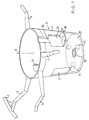
- a steering wheel skeleton for a vehicle steering wheel is shown, the has a steering wheel rim 3, several spokes 5 and a steering wheel hub 7.
- the Steering wheel hub 7 is cup-shaped and is open to the driver.
- the Cup-shaped hub is referred to below as a holding part. It should be emphasized that it is also possible to have a separate holding part on a disk-shaped hub put and attach to it to a receptacle for an airbag module create.
- On the circumference of the preferably circular cylindrical Holding part, which bears the reference number 9, are in the cylinder wall evenly distributed (see FIG. 2) three window-like recesses 11 are provided.
- the angles ⁇ 1 to ⁇ 3 should be the positions of the recesses 11 in Define circumferential direction.
- the end wall of the pot-shaped holding part has several axially inwards protruding pin 17, which are used as stops for the in the holding part 9 Serve airbag module.
- the steering shaft (not shown) is aligned with the longitudinal axis A of the vehicle steering wheel.
- the The steering shaft can also run eccentrically to the longitudinal axis A.
- An axially extending guide groove 25 is by pressing Cylinder wall of the holding part is formed and is used for simplified insertion of Airbag module in the holding part 9.
- the gas bag module which is only shown in sections in FIG. 3, has a gas generator 31, a gas bag 33 and a cup-shaped Generator carrier 35, which is also a kind of container for the gas bag module forms.
- a front cover 37 closes the gas bag module to the outside and is attached to the generator support 35.
- the generator carrier 35 has in the area of the recesses 11 also recesses 39, which are part of a Form locking connection.
- the gas bag module is fixed in the holding part 9 via three snap connections.
- the locking connections each consist of a spring element in the form of a formed spring plate 41 and the corresponding recess 39.
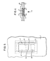
- Each spring plate 41 consists of an elongated sheet metal part, which in Has a plastic coating 43 in the area of its upper and lower end.
- the plastic encapsulation 43 can also the spring plate 41 like a frame surround.
- the spring plate 41 has an H-shaped stamping Recess 45, which define two metal tabs 47, 49.
- the sheet metal rags are thus only connected on one side to the rest of the spring plate 41 and thus only stored on one side.
- the sheet metal tab 47 forms a so-called first section and the metal tab 49 a so-called second section of the spring plate 41.
- the second section 49 is bent radially inwards, whereas the first Section 47 is V-shaped in cross section and with the tip of the "V" protrudes radially in the direction of the longitudinal axis A.
- Section 47 has one in FIG. 3 shown, upper, gradually radially inwardly extending part 51 and an adjoining abruptly extending part 53.
- the spring plate 41 and the extrusion 43 form an insert as separate, pre-assembled unit, which is pressed into the recess 11 from the inside is locked in place. This locking takes place accordingly formed longitudinal edges of the spring plate 41, the longitudinal edges so-called form third section 61 of the spring plate 41.
- the gas bag module used later against the inserts Falling out secures.
- the inserts can be used in this case as they are radially inward protrude, also serve as a guide for the gas bag module, as shown in FIG. 4.
- the gas bag module must be axially downwards to actuate the horn pressed until two contacts (one on the gas generator support and one on the end wall 21) touch each other. With this movement, the second Section 49 bent elastically. If the driver is no longer on that Presses gas bag module, the second section 49 pushes the gas bag module again upwards into the basic position shown in FIG. 3.
- the stops 17 can also Pick up contacts or microswitches that serve to operate the horn.
Landscapes
- Engineering & Computer Science (AREA)
- Mechanical Engineering (AREA)
- Air Bags (AREA)
- Steering Controls (AREA)
Abstract
Description
- Fig. 1
- eine perspektivische Ansicht des Lenkradskeletts als Teil des erfindungsgemäßen Fahrzeuglenkrads,
- Fig. 2
- eine Draufsicht auf den Nabenbereich des in Fig. 1 gezeigten Lenkradskelettes,
- Fig. 3
- einen Längsschnitt durch das Fahrzeuglenkrad im Bereich der Nabe bei eingesetztem Gassackmodul,
- Fig. 4
- einen Schnitt längs der Linie IV-IV in Fig. 3 und
- Fig. 5
- eine Ansicht eines als Einsatz ausgebildeten Federelementes in Richtung des Pfeils X in Fig. 4.
Claims (12)
- Fahrzeuglenkrad, mitdadurch gekennzeichnet, daßeiner Längsachse (A),einer Lenkradnabe (7),einem Halteteil (9),einem Gassackmodul, das über wenigstens eine Rastverbindung mit dem Halteteil (9) verbunden ist und das zur Hupenbetätigung in Richtung Längsachse (A) verschieblich gelagert ist,
die Rastverbindung ein einstückiges, in eine Ausnehmung (39) schnappendes Federelement aufweist, das verrastend das Gassackmodul und das Halteteil (9) miteinander verbindet und das zudem das Gassackmodul bei Hupenbetätigung in eine Grundstellung zurückbewegt. - Fahrzeuglenkrad nach Anspruch 1, dadurch gekennzeichnet, daß das Federelement ein umgeformtes Federblech (41) ist.
- Fahrzeuglenkrad nach Anspruch 2, dadurch gekennzeichnet, daß das Federblech (41) ein kunststoffumspritzter Einsatz ist.
- Fahrzeuglenkrad nach einem der vorhergehenden Ansprüche, dadurch gekennzeichnet, daß das Federelement einen ersten Abschnitt (47) zur Schaffung der Rastverbindung und einen zweiten Abschnitt (49) zur Schaffung einer Rückstellkraft bei Hupenbetätigung hat.
- Fahrzeuglenkrad nach Anspruch 4, dadurch gekennzeichnet, daß der erste Abschnitt (47) ein im Querschnitt V-förmiger, in die Ausnehmung (39) ragender umgeformter Abschnitt des als Federblech (41) ausgebildeten Federelements ist.
- Fahrzeuglenkrad nach Anspruch 4 oder 5, dadurch gekennzeichnet, daß der zweite Abschnitt (49) ein radial bezüglich der Längsachse (A) abstehender, gebogener Abschnitt des als Federblech (41) ausgebildeten Federelements ist.
- Fahrzeuglenkrad nach Anspruch 6, dadurch gekennzeichnet, daß der zweite Abschnitt (49) das Gassackmodul in der Grundstellung des Gassackmoduls so gegen den ersten Abschnitt (47) drückt, daß das Gassackmodul in der Grundstellung spielfrei gelagert ist.
- Fahrzeuglenkrad nach einem der Ansprüche 4 bis 7, dadurch gekennzeichnet, daß das Federblech eine H-förmige Ausnehmung (45) hat, durch die zwei einseitig gelagerte Blechlappen definiert sind, die den ersten und den zweiten Abschnitt (47, 49) bilden.
- Fahrzeuglenkrad nach einem der vorhergehenden Ansprüche, dadurch gekennzeichnet, daß das Federelement ein an dem Halteteil (9) oder dem Gassackmodul befestigter separater Einsatz ist.
- Fahrzeuglenkrad nach Anspruch 9, dadurch gekennzeichnet, daß das Federelement ein Federblech (41) mit einem dritten Abschnitt (61) ist, mit dem es am Halteteil (9) oder am Gassackmodul befestigt ist.
- Fahrzeuglenkrad nach einem der vorhergehenden Ansprüche, dadurch gekennzeichnet, daß das Halteteil (9) die topfförmig ausgebildete Lenkradnabe (7) ist, in die das Gassackmodul eingesetzt ist.
- Fahrzeuglenkrad nach Anspruch 11, dadurch gekennzeichnet, daß das Halteteil (9) und das Gassackmodul eine axial verlaufende Führung (25) haben, die das Gassackmodul umfangsmäßig im Halteteil (9) positioniert.
Applications Claiming Priority (2)
| Application Number | Priority Date | Filing Date | Title |
|---|---|---|---|
| DE20006595U | 2000-04-10 | ||
| DE20006595U DE20006595U1 (de) | 2000-04-10 | 2000-04-10 | Fahrzeuglenkrad |
Publications (3)
| Publication Number | Publication Date |
|---|---|
| EP1145922A2 true EP1145922A2 (de) | 2001-10-17 |
| EP1145922A3 EP1145922A3 (de) | 2003-06-25 |
| EP1145922B1 EP1145922B1 (de) | 2005-06-15 |
Family
ID=7940066
Family Applications (1)
| Application Number | Title | Priority Date | Filing Date |
|---|---|---|---|
| EP01107434A Expired - Lifetime EP1145922B1 (de) | 2000-04-10 | 2001-03-27 | Fahrzeuglenkrad mit verschieblich gelagertem Gassackmodul |
Country Status (3)
| Country | Link |
|---|---|
| US (1) | US6672613B2 (de) |
| EP (1) | EP1145922B1 (de) |
| DE (2) | DE20006595U1 (de) |
Cited By (1)
| Publication number | Priority date | Publication date | Assignee | Title |
|---|---|---|---|---|
| US11479199B2 (en) * | 2020-08-18 | 2022-10-25 | Autoliv Development Ab | Vehicle steering wheel comprising a steering wheel cladding and a safety module |
Families Citing this family (5)
| Publication number | Priority date | Publication date | Assignee | Title |
|---|---|---|---|---|
| DE202005019960U1 (de) * | 2005-12-21 | 2006-04-13 | Trw Automotive Safety Systems Gmbh | Gassackmodul |
| DE202006014054U1 (de) | 2006-09-13 | 2006-12-21 | Trw Automotive Safety Systems Gmbh | Fahrzeuglenkrad |
| ES1064485Y (es) * | 2006-12-28 | 2007-06-16 | Seat Sa | Modulo airbag con circuito de claxon para volante de vehiculos |
| DE202018106051U1 (de) * | 2018-10-23 | 2020-01-24 | Dalphi Metal Espana, S.A. | Skelett für eine Fahrzeuglenkvorrichtung sowie Fahrzeuglenkvorrichtung mit einem solchen Skelett |
| CN117300812B (zh) * | 2023-11-29 | 2024-02-23 | 广州市海拉汽车零件制造有限公司 | 一种汽车助力转向器零部件智能生产设备 |
Family Cites Families (14)
| Publication number | Priority date | Publication date | Assignee | Title |
|---|---|---|---|---|
| US5303952A (en) * | 1992-12-23 | 1994-04-19 | United Technologies Automotive, Inc. | Electric signalling in a supplemental vehicle restraint system |
| US5350190A (en) | 1993-07-06 | 1994-09-27 | Primrose, Inc. | Air bag assembly mount including snap-fit horn attachment |
| DE9402752U1 (de) * | 1994-02-21 | 1994-04-28 | Camloc GmbH, 65779 Kelkheim | Verschlußeinrichtung zum lösbaren Verbinden zweier Bauteile |
| US5627352A (en) * | 1994-09-28 | 1997-05-06 | Toyoda Gosei Co., Ltd. | Steering wheel |
| JPH08207783A (ja) | 1994-12-07 | 1996-08-13 | Toyoda Gosei Co Ltd | ステアリングホイール |
| JP3538977B2 (ja) * | 1995-07-21 | 2004-06-14 | 豊田合成株式会社 | ステアリングホイール |
| US5599039A (en) * | 1995-07-21 | 1997-02-04 | Textron Inc. | Spring retainer air bag mounting device |
| US5788268A (en) * | 1995-07-21 | 1998-08-04 | Textron Inc. | Spring retainer air bag mounting device |
| US5738369A (en) * | 1996-10-09 | 1998-04-14 | Breed Automotive Technology, Inc. | Snap-on air bag and horn switch module |
| US6017055A (en) * | 1997-11-03 | 2000-01-25 | Trw Inc. | Vehicle occupant protection apparatus |
| DE29722824U1 (de) | 1997-12-24 | 1998-04-02 | TRW Automotive Safety Systems GmbH, 63743 Aschaffenburg | Lenkrad mit einem Airbagmodul |
| US6250666B1 (en) * | 1998-03-23 | 2001-06-26 | Breed Automotive Technology, Inc. | Airbag housing with horn mechanism |
| GB2336135B (en) * | 1998-04-06 | 2002-01-23 | Autoliv Dev | Improvements in or relating to an airbag arrangement |
| US6302432B1 (en) * | 1999-10-12 | 2001-10-16 | Trw, Inc. | Deflection tab baseplate for an airbag inflator |
-
2000
- 2000-04-10 DE DE20006595U patent/DE20006595U1/de not_active Expired - Lifetime
-
2001
- 2001-03-27 EP EP01107434A patent/EP1145922B1/de not_active Expired - Lifetime
- 2001-03-27 DE DE50106493T patent/DE50106493D1/de not_active Expired - Lifetime
- 2001-04-10 US US09/829,456 patent/US6672613B2/en not_active Expired - Lifetime
Non-Patent Citations (1)
| Title |
|---|
| None |
Cited By (1)
| Publication number | Priority date | Publication date | Assignee | Title |
|---|---|---|---|---|
| US11479199B2 (en) * | 2020-08-18 | 2022-10-25 | Autoliv Development Ab | Vehicle steering wheel comprising a steering wheel cladding and a safety module |
Also Published As
| Publication number | Publication date |
|---|---|
| EP1145922B1 (de) | 2005-06-15 |
| DE20006595U1 (de) | 2000-08-17 |
| US6672613B2 (en) | 2004-01-06 |
| DE50106493D1 (de) | 2005-07-21 |
| US20010030413A1 (en) | 2001-10-18 |
| EP1145922A3 (de) | 2003-06-25 |
Similar Documents
| Publication | Publication Date | Title |
|---|---|---|
| DE602004011429T2 (de) | Hupenschalter und Gassackvorrichtung | |
| DE19725684C2 (de) | Lenkrad mit einem mittels Rastverbindung daran befestigten Airbagmodul | |
| DE20021532U1 (de) | Fahrzeuglenkrad | |
| DE20213908U1 (de) | Airbagmodul sowie Baugruppe aus einem Lenkrad und einem Airbagmodul | |
| EP2037153A2 (de) | Getriebegehäuse | |
| EP1183167A1 (de) | Vorrichtung zum übertragen von energie | |
| DE69908578T2 (de) | Airbaganordnung | |
| DE69125135T2 (de) | Schalteraufbau | |
| EP1145922B1 (de) | Fahrzeuglenkrad mit verschieblich gelagertem Gassackmodul | |
| DE102019211673A1 (de) | Befestigungselement für ein Gehäuse zum Befestigen des Gehäuses an einer Trägerstruktur und Montagesystem | |
| DE60123349T2 (de) | Befestigungsvorrichtung | |
| EP1251042A2 (de) | Gassack-Modul | |
| EP0675295A1 (de) | Befestigungsvorrichtung | |
| EP1475270A2 (de) | Baugruppe mit einem Lenkrad und einem Gassackmodul | |
| EP1757491B1 (de) | Fahrzeuglenkrad mit Gassackmodul | |
| DE10157440A1 (de) | Rasteinrichtung für ein Airbagmodul | |
| DE102007043560A1 (de) | Fahrzeuglenkrad | |
| EP1088737A2 (de) | Baugruppe mit Vorrichtung zum Ausrichten von zwei benachbarten Teilen | |
| DE4014754C2 (de) | Tastenelement mit Dämpfungsfedern | |
| DE2920836A1 (de) | Halterung fuer lautsprecher in kraftfahrzeugen | |
| EP1060957B1 (de) | Baueinheit für ein Gassack-Modul und Gassack-Modul | |
| DE102006015757A1 (de) | Becherhalter für ein Kraftfahrzeug | |
| EP0521528A1 (de) | Elektrischer Motor, insbesondere Scheibenwischermotor eines Kraftfahrzeugs | |
| DE102014003422B4 (de) | Vorrichtung zur Befestigung eines Gassackmoduls in einem Kraftfahrzeug, Lenkrad, Lenkradbaugruppe sowie Verfahren zur Herstellung einer Lenkradbaugruppe | |
| DE4019932C2 (de) | Anordnung zur Befestigung eines insbesondere für die Lagerung einer Betätigungsvorrichtung eines Kraftfahrzeugwechselgetriebes dienenden Gummilagers an einem Kraftfahrzeugaufbau |
Legal Events
| Date | Code | Title | Description |
|---|---|---|---|
| PUAI | Public reference made under article 153(3) epc to a published international application that has entered the european phase |
Free format text: ORIGINAL CODE: 0009012 |
|
| AK | Designated contracting states |
Kind code of ref document: A2 Designated state(s): AT BE CH CY DE DK ES FI FR GB GR IE IT LI LU MC NL PT SE TR |
|
| AX | Request for extension of the european patent |
Free format text: AL;LT;LV;MK;RO;SI |
|
| PUAL | Search report despatched |
Free format text: ORIGINAL CODE: 0009013 |
|
| AK | Designated contracting states |
Designated state(s): AT BE CH CY DE DK ES FI FR GB GR IE IT LI LU MC NL PT SE TR |
|
| AX | Request for extension of the european patent |
Extension state: AL LT LV MK RO SI |
|
| 17P | Request for examination filed |
Effective date: 20031208 |
|
| AKX | Designation fees paid |
Designated state(s): DE ES FR GB IT |
|
| 17Q | First examination report despatched |
Effective date: 20040614 |
|
| GRAP | Despatch of communication of intention to grant a patent |
Free format text: ORIGINAL CODE: EPIDOSNIGR1 |
|
| GRAS | Grant fee paid |
Free format text: ORIGINAL CODE: EPIDOSNIGR3 |
|
| GRAA | (expected) grant |
Free format text: ORIGINAL CODE: 0009210 |
|
| RAP1 | Party data changed (applicant data changed or rights of an application transferred) |
Owner name: TRW AUTOMOTIVE SAFETY SYSTEMS GMBH |
|
| AK | Designated contracting states |
Kind code of ref document: B1 Designated state(s): DE ES FR GB IT |
|
| PG25 | Lapsed in a contracting state [announced via postgrant information from national office to epo] |
Ref country code: IT Free format text: LAPSE BECAUSE OF FAILURE TO SUBMIT A TRANSLATION OF THE DESCRIPTION OR TO PAY THE FEE WITHIN THE PRESCRIBED TIME-LIMIT;WARNING: LAPSES OF ITALIAN PATENTS WITH EFFECTIVE DATE BEFORE 2007 MAY HAVE OCCURRED AT ANY TIME BEFORE 2007. THE CORRECT EFFECTIVE DATE MAY BE DIFFERENT FROM THE ONE RECORDED. Effective date: 20050615 Ref country code: GB Free format text: LAPSE BECAUSE OF FAILURE TO SUBMIT A TRANSLATION OF THE DESCRIPTION OR TO PAY THE FEE WITHIN THE PRESCRIBED TIME-LIMIT Effective date: 20050615 |
|
| REG | Reference to a national code |
Ref country code: GB Ref legal event code: FG4D Free format text: NOT ENGLISH |
|
| REF | Corresponds to: |
Ref document number: 50106493 Country of ref document: DE Date of ref document: 20050721 Kind code of ref document: P |
|
| PG25 | Lapsed in a contracting state [announced via postgrant information from national office to epo] |
Ref country code: ES Free format text: LAPSE BECAUSE OF FAILURE TO SUBMIT A TRANSLATION OF THE DESCRIPTION OR TO PAY THE FEE WITHIN THE PRESCRIBED TIME-LIMIT Effective date: 20050926 |
|
| GBV | Gb: ep patent (uk) treated as always having been void in accordance with gb section 77(7)/1977 [no translation filed] |
Effective date: 20050615 |
|
| PLBE | No opposition filed within time limit |
Free format text: ORIGINAL CODE: 0009261 |
|
| STAA | Information on the status of an ep patent application or granted ep patent |
Free format text: STATUS: NO OPPOSITION FILED WITHIN TIME LIMIT |
|
| 26N | No opposition filed |
Effective date: 20060316 |
|
| EN | Fr: translation not filed | ||
| PG25 | Lapsed in a contracting state [announced via postgrant information from national office to epo] |
Ref country code: FR Free format text: LAPSE BECAUSE OF FAILURE TO SUBMIT A TRANSLATION OF THE DESCRIPTION OR TO PAY THE FEE WITHIN THE PRESCRIBED TIME-LIMIT Effective date: 20060811 |
|
| PG25 | Lapsed in a contracting state [announced via postgrant information from national office to epo] |
Ref country code: FR Free format text: LAPSE BECAUSE OF FAILURE TO SUBMIT A TRANSLATION OF THE DESCRIPTION OR TO PAY THE FEE WITHIN THE PRESCRIBED TIME-LIMIT Effective date: 20050615 |
|
| PGFP | Annual fee paid to national office [announced via postgrant information from national office to epo] |
Ref country code: DE Payment date: 20180331 Year of fee payment: 18 |
|
| REG | Reference to a national code |
Ref country code: DE Ref legal event code: R119 Ref document number: 50106493 Country of ref document: DE |
|
| PG25 | Lapsed in a contracting state [announced via postgrant information from national office to epo] |
Ref country code: DE Free format text: LAPSE BECAUSE OF NON-PAYMENT OF DUE FEES Effective date: 20191001 |