EP1147939A2 - Motorgetriebene Sitzfussstütze - Google Patents
Motorgetriebene Sitzfussstütze Download PDFInfo
- Publication number
- EP1147939A2 EP1147939A2 EP01109521A EP01109521A EP1147939A2 EP 1147939 A2 EP1147939 A2 EP 1147939A2 EP 01109521 A EP01109521 A EP 01109521A EP 01109521 A EP01109521 A EP 01109521A EP 1147939 A2 EP1147939 A2 EP 1147939A2
- Authority
- EP
- European Patent Office
- Prior art keywords
- footrest
- motor
- driven
- seat
- footrest device
- Prior art date
- Legal status (The legal status is an assumption and is not a legal conclusion. Google has not performed a legal analysis and makes no representation as to the accuracy of the status listed.)
- Withdrawn
Links
Images


Classifications
-
- B—PERFORMING OPERATIONS; TRANSPORTING
- B60—VEHICLES IN GENERAL
- B60N—SEATS SPECIALLY ADAPTED FOR VEHICLES; VEHICLE PASSENGER ACCOMMODATION NOT OTHERWISE PROVIDED FOR
- B60N3/00—Arrangements or adaptations of other passenger fittings, not otherwise provided for
- B60N3/06—Arrangements or adaptations of other passenger fittings, not otherwise provided for of footrests
- B60N3/063—Arrangements or adaptations of other passenger fittings, not otherwise provided for of footrests with adjustment systems
-
- B—PERFORMING OPERATIONS; TRANSPORTING
- B60—VEHICLES IN GENERAL
- B60N—SEATS SPECIALLY ADAPTED FOR VEHICLES; VEHICLE PASSENGER ACCOMMODATION NOT OTHERWISE PROVIDED FOR
- B60N2/00—Seats specially adapted for vehicles; Arrangement or mounting of seats in vehicles
- B60N2/62—Thigh-rests
Definitions
- the present invention relates in general to automotive seats and more particularly to automotive seats of a type which is equipped with a footrest device for putting thereon the feet of a seat occupant. More specifically, the present invention is concerned with a motor-driven footrest device for an automotive seat, which has an Ottoman (viz., footrest) movable between an operative (or projected) position and an inoperative (or stowed) position by an electric power.
- Ottoman viz., footrest
- the device of the publication generally comprises an electric drive unit, a slider unit having a sliding rail driven by the electric drive unit, a link unit actuated by the slider rail and an Ottoman (viz., footrest) driven by the link unit to move between an operative (viz., projected) position and an inoperative (viz., stowed) position.
- an operative (viz., projected) position a link unit actuated by the slider rail
- an Ottoman viz., footrest
- the known footrest device of the publication has failed to provide makers and users with a satisfaction.
- the complicated construction tends to induce not only a bulky and heavier structure but also a time-consumed assembling work and thus bring about costly products of the footrest device.
- a motor-driven footrest device of a seat which comprises a footrest; an expanding mechanism having one end equipped with the footrest, the expanding mechanism being movable to assume a shrunk condition wherein the footrest is received in an opening formed in a seat cushion of the seat and an expanded condition wherein the footrest is projected from the opening to permit a seat occupant's feet to put thereon; an electric drive unit connected to the other end of the expanding mechanism to move the same to assume the shrunk condition and the expanded condition by the force of an electric power; and a mounting structure secured to a base structure of the seat, the mounting structure carrying both of the expanding mechanism and the electric drive unit.
- a motor-driven footrest device for use with a sliding seat, which comprises a footrest; an expanding mechanism having one end equipped with the footrest, the expanding mechanism being movable to assume a shrunk condition where the footrest is received in an opening formed in a seat cushion of the seat and an expanded condition wherein the footrest is projected from the opening to permit the feet of a seat occupant to be put thereon; an electric drive unit connected to the other end of the expanding mechanism to move the same to assume the shrunk condition and the expanded condition by the force of an electric power; a seat slide mechanism for sliding the seat, the seat slide mechanism including two fixed rails secured to a fixed structure, and two slide rails slidably engaged with the fixed rails and mounting thereon the seat; and a mounting structure secured to the two slide rails to move therewith, the mounting structure carrying both of the expanding mechanism and the electric drive unit.
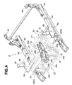
- FIGs. 1 and 2 there is shown an automotive seat 1 (particularly, front passenger's seat) to which the motor-driven footrest device 4 according to the present invention is practically applied.
- the seat 1 comprises a seat cushion 2 and a seat back 3 which is pivotally connected to a rear end of the seat cushion 2 through a reclining mechanism (not shown).
- the seat cushion 2 is formed at its front end portion with a rectangular opening 2a.
- the rectangular opening 2a receives therein an Ottoman 10 (viz., footrest) of the motor-driven footrest device 4 of the present invention.
- the seat cushion 2 generally comprises a cushion frame 5, a pad member 2b mounted on the cushion frame 5 and a skin member 2c covering the pad member 2b.
- the cushion frame 5 has two front connecting portions 5a and two rear connecting portions 5b, as shown.
- Denoted by numeral 6 is a power seat slide mechanism on which the seat cushion 2 is mounted.
- the power seat slide mechanism comprises two fixed rails 6a and 6b which are fixed to a floor of an associated motor vehicle, two slide rails 6c and 6d which are slidably engaged with the two fixed rails 6a and 6b and a drive mechanism 6f (see Fig. 5) which drives or moves the slide rails 6c and 6d relative to the fixed rails 6a and 6b by the force of an electric power.
- each slide rail 6c or 6d carries a threaded drive rod which has a screw thread formed therearound.
- the threaded drive rod is operatively engaged with a nut member (not shown) fixed to the fixed rail 6a or 6b, so that upon rotation of the threaded drive rod about its axis, the slide rail 6c or 6d slides on and along the fixed rail 6a or 6b forward or rearward.
- the drive mechanism 6f comprises an electric motor 6e which has output shafts. Each output shaft is connected through a speed reduction gear SRG to the corresponding drive rod in a manner to rotate the same.
- the slide rails 6c and 6d are. moved on and along the fixed rails 6a and 6b forward or rearward.
- the slide rails 6c and 6d have at their front portions base brackets 6g and 6h secured thereto.
- Two front cushion supporting brackets 6j and 6k are secured to the base brackets 6g and 6h respectively.
- the slide rails 6c and 6d have at their rear portions two rear cushion supporting brackets 6m and 6n secured thereto.
- the seat cushion 2 (more specifically, the seat 1) and the slide rails 6c and 6d constitute a single unit which is movable relative to the fixed rails 6a and 6b. That is, when the electric motor 6e is energized to rotate the output shafts in one direction, the seat 1 is moved forward or rearward relative to the fixed rails 6a and 6b.
- a mounting structure 60 which serves as a structural base of the motor-driven footrest device 4 of the present invention.
- the mounting structure 6o comprises two metal pipes 6p and 6q each extending between the base brackets 6g and 6h, and three, that is, first, second and third brackets 6s, 6r and 6t each extending between the two metal pipes 6p and 6q. It is to be noted that these elements are welded to the corresponding portions.
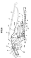
- the motor-driven footrest device 4 comprises two holding arms 8 which are secured to lower surfaces of the first and third brackets 6s and 6t of the mounting structure 6o.
- the Ottoman 10 is connected to the holding arms 8 through a first link mechanism 9 in such a manner that the Ottoman 10 is movable between an operative (viz., projected) position as shown in Fig. 8 and an inoperative (viz., stowed) position as shown in Fig. 7.
- the first link mechanism 9 comprises two front links 9A which are pivotally connected to the holding arms 8 and two rear links 9B which are pivotally connected to the holding arms 8. Leading ends of these front and rear links 9A and 9B are bent inward, as shown in Fig. 6.
- the leading ends of the front and rear links 9A and 9B are pivotally connected to respective supporting arms 13 which are respectively secured to side portions of a reversed U-shaped supporting frame 12.
- a supporting bracket 31 is secured to an upper bridge portion of the supporting frame 12 for the reason which will become apparent hereinafter.
- the reversed U-shaped supporting frame 12 constitutes a base structure of the Ottoman 10. That is, as is seen from Fig. 3, the side portions of the supporting frame 12 are formed with respective guide grooves 12b (see Figs. 3 and 12) in which a rectangular sliding frame 14 is slidably received. To the sliding frame 14, there are mounted a spring wire frame 15, a base frame 16, a pad member 17 and a trim member 18 to constitute the entirety of the Ottoman 10. The detailed construction of the Ottoman 10 will be described hereinafter.
- the distance between the pivoted portions of the front and rear links 9A and 9B of each unit to corresponding holding arm 8 is set larger than the distance between the pivoted portions of the front and rear links 9A and 9B to the corresponding supporting arm 13.
- a drive mechanism 22 for moving the Ottoman 10 in the above-mentioned manner, there is further provided a drive mechanism 22.
- the drive mechanism 22 is installed in an elongate case 21 which is secured to a lower surface of the above-mentioned second bracket 6r of the mounting structure 6o.
- the elongate case 21 has a reversed U-shaped cross section and is arranged to cover the later-mentioned threaded drive shaft 26.
- the drive mechanism 22 comprises a motor unit which includes an electric motor 23, a speed reduction gear 24 having an input member engaged with an output member of the motor 23, an output shaft 25 extending from the speed reduction gear 24 and a threaded drive bolt 26 coaxially connected to the output shaft 25.
- the threaded drive bolt 26 may be of a double spiral type.
- the motor unit is pivotally held at the speed reduction gear 24 by the elongate case 21, and the leading end of the threaded drive bolt 26 is rotatably supported by a front end of the elongate case 21.
- a nut member 27 is operatively engaged with the threaded drive bolt 26.
- the threaded drive bolt 26 has front and rear stoppers 25B and 25A mounted thereon by which the axial movement of the nut member 27 relative to the bolt 26 is restricted.
- the second link mechanism 28 comprises a longer link member 29 which, as is seen from Fig. 8, has a rear or right end vertically pivotally connected to the nut member 27.
- the longer link member 29 generally comprises two parallel side walls 29a and 29b and front and rear connecting walls 29c and 29d each extending between the side walls 29a and 29b.
- the parallel side walls 29a and 29b have at rear or right ends thereof circular openings 29p respectively and at front or left portions thereof outwardly swelled portions 29e and 29f respectively.
- Each swelled front portion 29e or 29f is provided with an outwardly projected pin 29m for the reasons which will be described hereinafter.
- each side wall 29a or 29b has at front and rear portions of the swelled front portion 29e or 29f front and rear inclined walls (no numerals).
- Each of these front and rear inclined walls is formed with a reinforcing ridge (or bead) 29k for reinforcing such inclined walls.
- each side wall 29a or 29b has near the rear inclined wall an elongate cut 29g or 29h, and near the front inclined wall an opening 29i or 29j.
- These cuts 29g and 29h and the openings 29i and 29j are used for providing the longer link member 29 with a suitable flexibility, that is, suitable shock absorbing ability. That is, when an abnormally big force is applied to the longer link member 29 from a front (or left) direction, the swelled front portions 29e and 29f are forced to expand outward reducing the length of the longer link member 29.
- each cut 29g or 29h extends upward from a lower edge of the side wall 29a or 29b to a middle portion of the same. Due to the nature of the cuts 29g and 29h and provision of the openings 29i and 29j, the front portion of the longer link member 29 has a tendency to be bent downward upon receiving such big force.
- the front (or left) end of the longer link member 29 is pivotally connected to lower ends of two links 30 of which upper ends are pivotally connected to a shaft 14b fixed to a rear center part of the rectangular sliding frame 14 (see Fig. 3).
- the two links 30 become in parallel with the sliding frame 14.
- the outwardly projected pins 29m of the longer link member 29 are pivotally held by the above-mentioned supporting bracket 31 fixed to the sliding frame 14.
- the nut member 27 is pivotally connected to the circular openings 29p of the longer link member 29 through respective spacers 29r.
- the drive mechanism 22, the first link mechanism 9 and the second link mechanism 28 constitute a so-called expanding mechanism for the Ottoman 10.
- a modification 29' of the longer link mechanism 29 there is shown a modification 29' of the longer link mechanism 29.
- the radially swelled portions 29e and 29f are semi-cylindrical in shape and the elongate cuts 29g and 29h are triangular in shape. Due to similarity of this modification 29' to the longer link member 29, similar function to the longer link member 29 is possessed by the modification 29'.
- the rectangular sliding frame 14, the spring wire frame 15, the base frame 16 and the trim member 18 constitute the entirety of the Ottoman 10.
- the spring wire frame 15 is used for providing the Ottoman with a suitable resiliency.
- the sliding frame 14 has plastic sliders 19A and 19B fixed to side edges thereof for smoothing movement in the guide grooves of the supporting frame 12.
- each plastic slider 19A or 19B generally comprises a longer side wall 19b and a shorter front wall 19c which are united, and thus each plastic slider has a generally L-shaped cross section.
- Each slider 19A or 19B is formed with various engaging pawls 19a, 19d and 19e.
- each slider 19A or 19B is formed at the inner surface thereof with inwardly projected two boss portions 19f and at the outer surface thereof with two elongate recesses 19g and 19h.
- the longer side wall 19b covers the corresponding side edge 14a of the sliding frame 14, and the engaging pawls 19a engage an open end of the sliding frame 14.
- the shorter front wall 19c mates with the front wall portion 14b of the sliding frame 14.
- the engaging paws 19d and 19e project obliquely.
- the two boss portions 19f are engaged with engaging openings 14c formed in the front wall portion 14b of the sliding frame 14. Due to provision of the two elongate recesses 19g and 19h, the sliding movement of the slider 19A or 19B relative to the guide frame 12b of the supporting frame 12 is smoothly made.
- Figs. 13A to 13C show the steps for assembling each slider 19A or 19B to the corresponding side edge 14a of the sliding frame 14. That is, as is shown in Fig. 13A, at first, the engaging pawls 19 of the slider 19A or 19B is brought into engagement with the open end of the sliding frame 14. With this, the boss portions 19f are brought into contact with a rounded outer surface of the sliding frame 14, which is defined between side edge 14a and the front wall portion 14b. Then, keeping this condition, a certain external force is applied to the slider 19A or 19B to press the same toward the side edge 14a. With this, as is seen from Fig.
- the sliding frame 14 comprises a rectangular base portion 14A which has the side edges equipped with the above-mentioned sliders 19A and 19B, and a smaller rectangular portion 14B which is integrally formed on a front face of the base portion 14A.
- the smaller rectangular portion 14B is formed with four bolt holes 14C.
- the wire frame 15 generally comprises a rectangular metal block 15a which is secured to the front face of the smaller rectangular portion 14B of the sliding frame 14, and a pair of rectangular wire structures 15b and 15c which are secured to the metal block 15a and extend radially outwardly as shown.
- the metal block 15a For securing the metal block 15a to the smaller rectangular portion 14B, four bolts 15d are used, each passing through a bolt hole 15e of the metal block 15a and the above-mentioned bolt hole 14C of the smaller rectangular portion 14B.
- each bolt hole 15e is formed somewhat greater than the diameter of the bolt 15d.
- Each wire structure 15b or 15c is made of a steel wire and has both ends welded to the metal block 15a.
- the base frame 16 is sized to cover the wire frame 15, and comprises a flat major portion 16a and a side wall portion 16b which extend along the side and lower edges of the major portion 16a.
- On a rear upper surface of the major portion 16a there are formed four hooks 16c which catch J-hooks 18a (see Fig. 8) provided by the trim member 18.
- While on a rear lower surface of the major portion 16a there are provided two rear hooks 16d and 16e which catch lower sections of the rectangular wire structures 15b and 15c respectively.
- the major portion 16a of the base frame 16 is formed at upper sides thereof with two small openings 16f and 16g by which respective plastic clips 16h and 16i are held. In assembly, the clips 16h and 16i hold upper sections of the rectangular wire structures 15b and 15c.
- each clip 16h or 16i comprises a flat part 16j, front and rear side parts 16m and 16n which extend from front and rear ends of the flat part 16j, two bent back parts 160 and 16p which extend obliquely upward from lower ends of the front and rear side parts 16m and 16n, two wire holding parts 16q and 16q' which are arranged to face the bent back parts 16o and 16p, a triangular engaging part 16r which is formed on the flat part 16j and two resilient tongue parts 16t and 16u which extend obliquely outward from the flat part 16j.
- the pad member 17 comprises a thicker pad proper 17a which is bonded to the flat major portion 16a of the base frame 16 (see Fig. 14) and a side wall portion 17b which extends along the side and lower edges of the pad proper 17a and is bonded to the side wall portion 16b of the base frame 16.
- the positional relation between the pad member 17 and the base frame 16 is clearly understood from Fig. 3.
- the trim cover 18 is shaped and sized to cover the pad member 17. As shown in Fig. 8, at one end of the trim cover 18, there are provided a first group of J-hooks 18a which are engaged with the lower edge of the side wall portion 16b of the base frame 16, and at the other end of the trim cover 18, there are provided a second group of J-hooks 18b which are engaged with the hooks 16c of the base frame 16.
- the pad member 17 is fixed to the base frame 16 by using a suitable adhesive, and then the trim member 18 is fixed to the pad member 17 having the J-hooks 18a and 18b respectively engaged with the side wall portion 16b of the base frame 16 and the hooks 16c of the same.
- the plastic clips 16h and 16i are fixed to the base frame 16 having the triangular engaging parts 16r mated with the two openings 16f and 16g of the base frame 16. Due to function of the resilient tongue parts 16t and 16u pressed against the lower surface of the flat major portion 16a of the major frame 16, the clips 16h and 16i can be tightly fitted to the base frame 16 without producing undesirable play.
- the sliding frame 14 is attached to the rear surface of the base frame 16 in such a manner that the lower sections of the paired rectangular wire structures 15b and 15c thereof abut against the rear hooks 16d and 16e of the base frame 16.
- the sliding frame 14 is somewhat moved so as to induce a contact between the lower sections of the wire structures 15b and 15c and leading ends of the rear hooks 16d and 16e of the base frame 16 and then the unit of the base frame 16, pad member 17 and trim member 18 is pivoted in a counterclockwise direction in Fig. 16B so as separate the clips 16h and 16i from upper sections of the wire structures 15b and 15c.
- the unit of the base frame 16, pad member 17 and trim member 18 is pivoted in a clockwise direction in Fig. 16C about the mutually engaged portion between the lower sections of the wire structures 15b and 15c and the rear hooks 16d and 16e.
- the upper sections of the wire structures 15b and 15c are gripped by the respective clips 16h and 16i. That is, the unit (16, 17 and 18) is properly coupled with the sliding frame 14 to constitute the Ottoman 10 (viz., footrest).
- the nut member 27 takes a deeper position relative to the threaded drive bolt 26 causing the Ottoman 10 to assume the stowed position wherein the Ottoman 10 is neatly received in the rectangular opening 2a formed in the front end portion of the seat cushion 2. That is, as has been described hereinabove, the distance between the pivoted portion of the front link 9A to the holding arm 8 and the pivoted portion of the rear link 9B to the holding arm 8 is determined larger than the distance between the pivoted portion of the front link 9A to the supporting arm 13 and the pivoted portion of the rear link 9B to the supporting arm 13. Under the stowed condition of the Ottoman 10, the front and rear links 9A and 9B of the first link .
- the mechanism 9 come close to each other showing an inclination angle of about 30 degrees relative to a horizontal plane. That is, the first imaginary line passing through the pivoted portions of the front and rear links 9A and 9B to the corresponding holding arm 8 and a second imaginary line passing through the pivoted portions of the front and rear links 9A and 9B to the corresponding supporting arm 13 cross each other at an acute angle, so that the Ottoman 10 inclines by about 70 degrees relative to the horizontal plane as shown.
- the sliding frame 14 is deeply received in the guide grooves 12b of the reversed U-shaped supporting frame 12, so that the supporting frame 12 is fully concealed by the Ottoman 10 and the upper end of the pad member 17 abuts against the lower surface of the seat cushion 2 leaving the lower end of the pad member 17 away from the vehicle floor.
- the Ottoman 10 When now the control switch is manipulated to turn the electric motor 23 to in the other direction, the Ottoman 10 is gradually brought to the inoperative (or stowed) position carrying out a reversed operation of the motor-driven footrest device 4.
- the nut member 27 When the Ottoman 10 is brought to the inoperative position, the nut member 27 abuts against the rear stopper 25A on the threaded drive bolt 26 and at the same time the energization of the electric motor 23 is canceled.
- the motor-driven footrest device 4 of the invention can be made into a module.
- the device 4 can be readily assembled before being fixed to the seat cushion 2.
- the longer link member 29 and its associated elements are constructed to absorb abnormally big force.
- the seat occupant's feet are safely protected even when, with his or her feed being put on the Ottoman 10, an associated motor vehicle encounters an head-on vehicle collision.
Landscapes
- Engineering & Computer Science (AREA)
- Transportation (AREA)
- Mechanical Engineering (AREA)
- Aviation & Aerospace Engineering (AREA)
- Passenger Equipment (AREA)
- Seats For Vehicles (AREA)
Applications Claiming Priority (8)
| Application Number | Priority Date | Filing Date | Title |
|---|---|---|---|
| JP2000115020 | 2000-04-17 | ||
| JP2000115016 | 2000-04-17 | ||
| JP2000115020A JP2001292862A (ja) | 2000-04-17 | 2000-04-17 | 電動オットマン装置 |
| JP2000115019 | 2000-04-17 | ||
| JP2000115016A JP2001292857A (ja) | 2000-04-17 | 2000-04-17 | 電動オットマン装置 |
| JP2000115019A JP3721934B2 (ja) | 2000-04-17 | 2000-04-17 | 電動オットマン装置 |
| JP2000115021A JP2001292860A (ja) | 2000-04-17 | 2000-04-17 | 電動オットマン装置 |
| JP2000115021 | 2000-04-17 |
Publications (2)
| Publication Number | Publication Date |
|---|---|
| EP1147939A2 true EP1147939A2 (de) | 2001-10-24 |
| EP1147939A3 EP1147939A3 (de) | 2003-10-15 |
Family
ID=27481225
Family Applications (1)
| Application Number | Title | Priority Date | Filing Date |
|---|---|---|---|
| EP01109521A Withdrawn EP1147939A3 (de) | 2000-04-17 | 2001-04-17 | Motorgetriebene Sitzfussstütze |
Country Status (2)
| Country | Link |
|---|---|
| US (1) | US20010048239A1 (de) |
| EP (1) | EP1147939A3 (de) |
Cited By (9)
| Publication number | Priority date | Publication date | Assignee | Title |
|---|---|---|---|---|
| ES2257169A1 (es) * | 2004-08-23 | 2006-07-16 | Play, S.A. | Silla infantil para automoviles. |
| NL1036481C2 (en) * | 2009-01-28 | 2010-07-30 | Maxi Miliaan Bv | A child vehicle seat provided with at least one leg rest, as well as a chassis suitable for such a child vehicle seat. |
| DE102010042880A1 (de) * | 2010-10-25 | 2012-05-16 | Brose Fahrzeugteile Gmbh & Co. Kommanditgesellschaft, Coburg | Verfahren zur Montage eines Fahrzeugsitzes mit einer Sitztiefenverstelleinrichtung |
| DE102011000477A1 (de) * | 2011-02-03 | 2012-08-09 | Dr. Ing. H.C. F. Porsche Aktiengesellschaft | Lordosenstütze |
| DE102012003763A1 (de) * | 2012-02-24 | 2013-08-29 | Volkswagen Aktiengesellschaft | Modulares karosseriefestes Unterschenkelauflageteil mit pneumatisch veränderbarer Auflagefläche |
| KR101441558B1 (ko) * | 2010-10-25 | 2014-09-17 | 브로제 파르쪼이크타일레 게엠베하 운트 코. 카게, 코부르크 | 시트 깊이 조절 장치를 포함하는 차량 시트 |
| US10434919B2 (en) * | 2017-05-25 | 2019-10-08 | Toyota Boshoku Kabushiki Kaisha | Vehicle seat |
| US10464450B1 (en) * | 2016-09-12 | 2019-11-05 | Steven B. Peterson | Appendage support for child seat |
| US20230406257A1 (en) * | 2022-06-21 | 2023-12-21 | Ford Global Technologies, Llc | Seat assembly with deployable belt member |
Families Citing this family (20)
| Publication number | Priority date | Publication date | Assignee | Title |
|---|---|---|---|---|
| US7757318B2 (en) | 2004-09-13 | 2010-07-20 | Kreg Therapeutics, Inc. | Mattress for a hospital bed |
| US7676862B2 (en) | 2004-09-13 | 2010-03-16 | Kreg Medical, Inc. | Siderail for hospital bed |
| US7743441B2 (en) | 2004-09-13 | 2010-06-29 | Kreg Therapeutics, Inc. | Expandable width bed |
| US7779494B2 (en) | 2004-09-13 | 2010-08-24 | Kreg Therapeutics, Inc. | Bed having fixed length foot deck |
| JP5343363B2 (ja) * | 2008-01-31 | 2013-11-13 | アイシン精機株式会社 | シートクッション調整装置 |
| WO2009158018A1 (en) | 2008-06-27 | 2009-12-30 | Kreg Medical, Inc. | Bed with modified foot deck |
| JP5447139B2 (ja) * | 2010-04-23 | 2014-03-19 | トヨタ紡織株式会社 | 車両用シート |
| EP2891579A4 (de) * | 2012-08-31 | 2016-04-13 | Nhk Spring Co Ltd | Stromsitzbetriebsvorrichtung und stromsitz |
| CN104108334A (zh) * | 2013-04-19 | 2014-10-22 | 长春博泽汽车部件有限公司 | 汽车座椅 |
| US9844269B2 (en) * | 2013-05-10 | 2017-12-19 | L&P Property Management Company | Motorized linkage mechanism for hi-leg seating unit |
| EP2994019B1 (de) | 2013-05-10 | 2018-04-25 | L&P Property Management Company | Verbindungsmechanismus für eine sitzeinheit zum hochlegen der beine |
| US10179077B2 (en) | 2014-04-18 | 2019-01-15 | Kreg Medical, Inc. | Patient support with stand-up and sit features |
| KR101601545B1 (ko) * | 2014-11-25 | 2016-03-08 | 현대자동차주식회사 | 시트쿠션 익스텐션 장치 |
| EP3361907B1 (de) * | 2015-10-15 | 2019-11-20 | L&P Property Management Company | Motorisierter verbindungsmechanismus für eine sitzeinheit zum hochlegen der beine |
| US10035438B2 (en) * | 2016-02-22 | 2018-07-31 | Ford Global Technologies, Llc | Vehicle seat bottom with independently deployable devices |
| JP6770101B2 (ja) * | 2016-03-11 | 2020-10-14 | イノテック モーション ゲーエムベーハーInnotec Motion Gmbh | 引き込みおよび引き出し可能なフットレストを有する座席用シャーシ |
| EP3426095B1 (de) * | 2016-03-11 | 2021-09-01 | Innotec Motion GmbH | System umfassed ein fussstützenchassis und ein sitzmöbelchassis |
| KR101738062B1 (ko) | 2016-05-09 | 2017-05-19 | 현대자동차주식회사 | 레그레스트의 구조 |
| KR101924179B1 (ko) * | 2017-04-20 | 2019-02-22 | 대원산업 주식회사 | 차량용 레그레스트 |
| CA3212205A1 (en) * | 2021-04-21 | 2022-10-27 | Indiana Mills & Manufacturing, Inc. | Seat mounting clip system |
Citations (5)
| Publication number | Priority date | Publication date | Assignee | Title |
|---|---|---|---|---|
| JPH09206157A (ja) | 1996-01-31 | 1997-08-12 | Delta Kogyo Co Ltd | 椅子の足載せ台構造 |
| JP2000115016A (ja) | 1998-10-08 | 2000-04-21 | Kokusai Electric Co Ltd | 全二重無線機とその回り込み防止方法 |
| JP2000115021A (ja) | 1998-09-29 | 2000-04-21 | Kokusai Electric Co Ltd | スペクトル拡散信号の搬送波再生回路 |
| JP2000115019A (ja) | 1998-10-01 | 2000-04-21 | Nec Saitama Ltd | 携帯無線機 |
| JP2000115020A (ja) | 1998-09-28 | 2000-04-21 | Data Investments Ltd | 電子識別システムのための遅延リセット・モード・モデル |
Family Cites Families (4)
| Publication number | Priority date | Publication date | Assignee | Title |
|---|---|---|---|---|
| US5507562A (en) * | 1994-07-28 | 1996-04-16 | Wieland Designs Inc. | Extensible foot rest |
| JP3323989B2 (ja) * | 1998-05-28 | 2002-09-09 | ジョンソン コントロールズ オートモーティブ システムズ株式会社 | 電動オットマン装置 |
| JP2000037255A (ja) * | 1998-07-24 | 2000-02-08 | Ikeda Bussan Co Ltd | 車両用シート装置 |
| JP2000158995A (ja) * | 1998-11-25 | 2000-06-13 | Ikeda Bussan Co Ltd | 電動オットマン装置 |
-
2001
- 2001-04-17 US US09/835,846 patent/US20010048239A1/en not_active Abandoned
- 2001-04-17 EP EP01109521A patent/EP1147939A3/de not_active Withdrawn
Patent Citations (5)
| Publication number | Priority date | Publication date | Assignee | Title |
|---|---|---|---|---|
| JPH09206157A (ja) | 1996-01-31 | 1997-08-12 | Delta Kogyo Co Ltd | 椅子の足載せ台構造 |
| JP2000115020A (ja) | 1998-09-28 | 2000-04-21 | Data Investments Ltd | 電子識別システムのための遅延リセット・モード・モデル |
| JP2000115021A (ja) | 1998-09-29 | 2000-04-21 | Kokusai Electric Co Ltd | スペクトル拡散信号の搬送波再生回路 |
| JP2000115019A (ja) | 1998-10-01 | 2000-04-21 | Nec Saitama Ltd | 携帯無線機 |
| JP2000115016A (ja) | 1998-10-08 | 2000-04-21 | Kokusai Electric Co Ltd | 全二重無線機とその回り込み防止方法 |
Cited By (13)
| Publication number | Priority date | Publication date | Assignee | Title |
|---|---|---|---|---|
| ES2257169A1 (es) * | 2004-08-23 | 2006-07-16 | Play, S.A. | Silla infantil para automoviles. |
| NL1036481C2 (en) * | 2009-01-28 | 2010-07-30 | Maxi Miliaan Bv | A child vehicle seat provided with at least one leg rest, as well as a chassis suitable for such a child vehicle seat. |
| EP2213508A3 (de) * | 2009-01-28 | 2011-10-05 | Maxi Miliaan B.V. | Kinderfahrzeugsitz mit mindestens einer Beinstütze, sowie Rahmen für den Kinderfahrzeugsitz |
| KR101441558B1 (ko) * | 2010-10-25 | 2014-09-17 | 브로제 파르쪼이크타일레 게엠베하 운트 코. 카게, 코부르크 | 시트 깊이 조절 장치를 포함하는 차량 시트 |
| DE102010042880A1 (de) * | 2010-10-25 | 2012-05-16 | Brose Fahrzeugteile Gmbh & Co. Kommanditgesellschaft, Coburg | Verfahren zur Montage eines Fahrzeugsitzes mit einer Sitztiefenverstelleinrichtung |
| US9016785B2 (en) | 2010-10-25 | 2015-04-28 | Brose Fahrzeugteile Gmbh & Co. Kg, Coburg | Vehicle seat with a seat depth adjusting device |
| DE102011000477A1 (de) * | 2011-02-03 | 2012-08-09 | Dr. Ing. H.C. F. Porsche Aktiengesellschaft | Lordosenstütze |
| DE102012003763A1 (de) * | 2012-02-24 | 2013-08-29 | Volkswagen Aktiengesellschaft | Modulares karosseriefestes Unterschenkelauflageteil mit pneumatisch veränderbarer Auflagefläche |
| US10464450B1 (en) * | 2016-09-12 | 2019-11-05 | Steven B. Peterson | Appendage support for child seat |
| US10717375B1 (en) * | 2016-09-12 | 2020-07-21 | Steven B. Peterson | Appendage support for child seat |
| US10434919B2 (en) * | 2017-05-25 | 2019-10-08 | Toyota Boshoku Kabushiki Kaisha | Vehicle seat |
| US20230406257A1 (en) * | 2022-06-21 | 2023-12-21 | Ford Global Technologies, Llc | Seat assembly with deployable belt member |
| US12311869B2 (en) * | 2022-06-21 | 2025-05-27 | Ford Global Technologies, Llc | Seat assembly with deployable belt member |
Also Published As
| Publication number | Publication date |
|---|---|
| EP1147939A3 (de) | 2003-10-15 |
| US20010048239A1 (en) | 2001-12-06 |
Similar Documents
| Publication | Publication Date | Title |
|---|---|---|
| EP1147939A2 (de) | Motorgetriebene Sitzfussstütze | |
| JP4428666B2 (ja) | 乗員を中心に位置させる人間工学的支持装置および方法 | |
| JP3751278B2 (ja) | サブマリン現象防止クロスメンバを含む自動車シートのシート・パン | |
| JP3094053B2 (ja) | 車両用ステアリング装置 | |
| US6024406A (en) | Vehicle seat provided with a device for protecting the neck in the event of impact from behind | |
| EP3519276B1 (de) | Lenkanordnung mit formschluss und energieabsorption und pyrotechnischem aktuator | |
| JP2788120B2 (ja) | パワーシートアジャスタ用一体型上部レール | |
| JP2515089B2 (ja) | 駆動ギヤの力バイパス路を有するパワ―シ―トアジャスタ | |
| JP6962845B2 (ja) | 車両用シート | |
| JP5515853B2 (ja) | サイドサポート装置の作動機構およびそれを使用した車両用シートのサイドサポート装置 | |
| KR20020064902A (ko) | 자동차용 브레이크 페달 장치 | |
| US5755461A (en) | Energy absorbing device for a steering column | |
| JP2000127991A (ja) | 衝撃吸収式ステアリング装置および自動車 | |
| US6840560B2 (en) | Vehicular seat assembly having a movable headrest and a vehicle which incorporates the vehicular seat assembly | |
| KR20200076884A (ko) | 차량용 시트 트랙 장치 | |
| US11845487B2 (en) | Steering column breakaway and energy absorption apparatus | |
| JP5267528B2 (ja) | 衝撃吸収式ステアリング装置 | |
| JP3522627B2 (ja) | シートスライド装置 | |
| JP4834258B2 (ja) | リクライニング装置 | |
| KR20150069430A (ko) | 운전자 상해 방지 타입 페달 | |
| JP3903428B2 (ja) | 自動車のブレーキペダルの押され防止構造 | |
| JP4193630B2 (ja) | 衝撃吸収式ステアリングコラム装置 | |
| EP1555179A1 (de) | Einstellbare Pedaleinheit für Fahrzeuge | |
| JP2002284018A (ja) | ステアリング装置の取付構造 | |
| EP1778518B1 (de) | Drehmechanismus mit verlängertem hub |
Legal Events
| Date | Code | Title | Description |
|---|---|---|---|
| PUAI | Public reference made under article 153(3) epc to a published international application that has entered the european phase |
Free format text: ORIGINAL CODE: 0009012 |
|
| 17P | Request for examination filed |
Effective date: 20010417 |
|
| AK | Designated contracting states |
Kind code of ref document: A2 Designated state(s): AT BE CH CY DE DK ES FI FR GB GR IE IT LI LU MC NL PT SE TR |
|
| AX | Request for extension of the european patent |
Free format text: AL;LT;LV;MK;RO;SI |
|
| PUAL | Search report despatched |
Free format text: ORIGINAL CODE: 0009013 |
|
| AK | Designated contracting states |
Kind code of ref document: A3 Designated state(s): AT BE CH CY DE DK ES FI FR GB GR IE IT LI LU MC NL PT SE TR |
|
| AX | Request for extension of the european patent |
Extension state: AL LT LV MK RO SI |
|
| AKX | Designation fees paid |
Designated state(s): DE FR GB |
|
| STAA | Information on the status of an ep patent application or granted ep patent |
Free format text: STATUS: THE APPLICATION IS DEEMED TO BE WITHDRAWN |
|
| 18D | Application deemed to be withdrawn |
Effective date: 20060214 |