EP1148526A2 - Vorrichtung zum Entgasen und Verlöten von vormontierten Vakuumschaltröhren - Google Patents
Vorrichtung zum Entgasen und Verlöten von vormontierten Vakuumschaltröhren Download PDFInfo
- Publication number
- EP1148526A2 EP1148526A2 EP01109279A EP01109279A EP1148526A2 EP 1148526 A2 EP1148526 A2 EP 1148526A2 EP 01109279 A EP01109279 A EP 01109279A EP 01109279 A EP01109279 A EP 01109279A EP 1148526 A2 EP1148526 A2 EP 1148526A2
- Authority
- EP
- European Patent Office
- Prior art keywords
- soldering
- base plate
- bell
- vacuum
- excitation coil
- Prior art date
- Legal status (The legal status is an assumption and is not a legal conclusion. Google has not performed a legal analysis and makes no representation as to the accuracy of the status listed.)
- Withdrawn
Links
Images


Classifications
-
- H—ELECTRICITY
- H01—ELECTRIC ELEMENTS
- H01H—ELECTRIC SWITCHES; RELAYS; SELECTORS; EMERGENCY PROTECTIVE DEVICES
- H01H33/00—High-tension or heavy-current switches with arc-extinguishing or arc-preventing means
- H01H33/60—Switches wherein the means for extinguishing or preventing the arc do not include separate means for obtaining or increasing flow of arc-extinguishing fluid
- H01H33/66—Vacuum switches
- H01H33/662—Housings or protective screens
- H01H33/66207—Specific housing details, e.g. sealing, soldering or brazing
Definitions
- the invention relates to a device for degassing and soldering pre-assembled vacuum interrupters in a single soldering process.
- Vacuum interrupters for vacuum circuit breakers, vacuum contactors, vacuum load disconnectors in the medium voltage range and also in the low voltage range, for example as motor protection switches, are used in many ways.
- the construction of a vacuum interrupter is shown in the drawing in FIG shown an embodiment.
- the vacuum interrupter 1 comprises the movable head 12 and the fixed head 13 connected to each other facing ends are equipped with a contact piece.
- the actual vacuum tube is formed by the metallic cover parts 15, with an insulator 14 disposed therebetween.
- the movable conductor 12 is sealed from the lid by means of the bellows 16.
- the the External parts forming the vacuum tube are connected to one another via soldering points L. connected, as well as the contact pieces 18, 19 with the conductors 12, 13. Die Contact pieces are laterally surrounded by the cylindrical screen 17, the is also firmly connected to the cover 15 via a solder joint.
- the oldest method of manufacturing the vacuum interrupter namely degassing, Welding and soldering the parts is the so-called "pinch-off process".
- the parts made of stainless steel are first made for one hour pre-degassed at approx. 1000 ° C, then the fixed contact group and the movable one Contact group pre-soldered individually, and from these parts the complete Vacuum interrupter mounted and by means of a copper tube with a Ultra high vacuum pump system coupled, and subsequently during at least 24 hours heated to a temperature of 400 ° to 500 ° C, cooled and the hydraulic tube is ultra-high vacuum tight via a hydraulic press device squeezed together - pinched off. The vacuum interrupter is then separated from the ultra high vacuum pump system.
- a complete soldering cycle takes about 10 to 12 hours, depending on the batch. It is always a discontinuous process that works with the three work stages loading furnace, soldering batch, unloading furnace, connected.
- the invention has for its object a faster and cheaper Degassing and soldering process based on the one-shot-brazing method creating vacuum interrupters, especially energy and Reduce time spent.
- a device is proposed to achieve this object, the a base plate with at least one soldering place with a Breakthrough in the base plate for connecting a suction pump and a covering the opening on the base plate and detachable bell, and a bell surrounding the outside with excitation coil with a medium or high frequency energy Medium or high frequency regenerator for the excitation coil, and one inside the bell arranged, as a cylindrical pipe section for receiving at least one pre-assembled vacuum interrupter designed susceptor having.
- the vacuum interrupters As a holder for the vacuum interrupters is preferably in the opening one on the base plate or on the base plate above the opening grid-like mounting plate for inserting the pre-assembled vacuum interrupters intended.
- the grid-like structure of the mounting plate causes a high flow conductance when pumping out the gases.
- thermocouples For precise heating to reach the soldering temperature and cooling thermocouples are provided, which in the head region of the bell by means of a high vacuum-tight implementation are arranged. Pressure measuring elements are also used for the interior and for the suction line to the suction pump, one Ultra high vacuum pump system, provided to the appropriate degassing and to achieve the corresponding high vacuum with certainty.
- the recess on the underside of the base plate is preferred Permanently connected or vacuum-tight connectable suction ports are provided.
- Rapid heating by means of the excitation coil and is essential to the invention the associated susceptor which is made of a material that is very light absorbs magnetic field lines and absorb magnetic energy very quickly can.
- the susceptor is preferably made of soft magnetic Materials such as iron and iron alloys, e.g. Fe, FeNi, FeNiCo etc. built up. This is particularly true in the lower frequency spectrum. In the higher The range of the frequency spectrum used can also be higher melting metals and alloys such as B. Mo (molybdenum), W (tungsten), Ta (tantalum), stainless steels and super alloys can be used.
- the pre-assembled vacuum interrupter opens very quickly the desired soldering temperature can be heated.
- the arrangement is preferably such that the excitation coil is ring-shaped is formed and surrounds the bell, namely transversely to the vertical switching axis the vacuum interrupter arranged inside the bell, the excitation coil being approximately centered with respect to the vacuum interrupter surrounding susceptor is arranged.
- the susceptor on insulating supports spaced from the base plate to be arranged so that he has the areas of the vacuum interrupter to be soldered surrounds outside.
- the powers that the excitation coil can deliver can be between 1.2 kW vary up to approx. 30 kW, the frequencies between 3.5 kHz and approx. 1 MHz.
- An ultra-high vacuum pump is used as the suction pump so that the pressure inside the bell can be kept below 2 x 10 -7 mbar during the entire soldering process.
- the bell can be moved, in particular, for loading and unloading the soldering device can be lifted, for example by means of a lifting device.
- the base plate with more than is preferred equipped with a soldering station, d. H. with more than one opening, whereby a bell is assigned to each opening on the top and on the Bottom of a suction nozzle. All suction ports of a base plate are over Suction lines led to a high vacuum system, and each suction nozzle is for coupling and / or disconnecting the bell with the high vacuum pump corresponding high vacuum valve assigned.
- the heater in shape the excitation coil with generator is assigned to the soldering points in such a way that corresponding movement of the excitation coil and the generator each Soldering areas can be approached one after the other with one excitation coil.
- the excitation coil with the generator in between arranged rail movable and rotatable and liftable his. If the soldering locations are arranged on a disk, it can be circular the excitation coil with the generator be arranged in the middle and through corresponding rotary movement to the individual soldering points are moved. Furthermore, the generator can be carried out with a lifting device be equipped with a vertical lifting movement.
- the manufacturing system with multiple soldering stations and a generator and an excitation coil with a control device To be provided so that the manufacturing process can be carried out automatically, d. H. loading the soldering areas, evacuating the equipped soldering areas, the heating up, cooling down and the removal and re-loading what one after the other like on a carousel.
- the controller can via PC and / or by means of a PLC control.
- each soldering place for one or more vacuum interrupters With the smallest possible space requirement are extremely short evacuation times for the soldering place below the bell possible.
- the entire device for degassing and soldering vacuum interrupters requires low investment costs due to the simple structure, but with large production quantities of vacuum interrupters in one automated or semi-automated process produced in the plant can be.
- the temperature and also the pressure in the chamber can be measured very precisely and the manufacturing process can be controlled accordingly.
- the device according to the invention is particularly suitable for manufacturing of vacuum interrupters for switch disconnectors, vacuum contactors for medium voltage and low voltage.
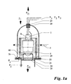
- FIG. 2 The construction of a vacuum interrupter for medium voltage and low voltage is shown by way of example in FIG. 2, as explained at the beginning.
- a vacuum interrupter for medium voltage and low voltage is shown by way of example in FIG. 2, as explained at the beginning.
- a soldering spot 2 for at least one or one small number of pre-assembled vacuum interrupters 1 is on a base plate 21 made of stainless steel.
- the soldering point 2 is on the base plate 21 an opening 27, for example in the form of a circle, is assigned.
- the top of the base plate is an annular groove around the opening 27 28 formed in which a sealing ring 22, for example a Viton O-ring, is arranged in a vacuum-tight manner connected to the base plate 21.
- a sealing ring 22 for example a Viton O-ring
- the bell 20 made of quartz glass put on.
- the suction nozzle 24 is on the underside of the base plate 21 connected to the recess 27 in a highly vacuum-tight manner, with one here Ultra high vacuum pump system, not shown, is connected.
- a high vacuum-tight bushing 23 for Thermocouples T1, T2, T3 or more to record the temperatures inside the bell jar during the manufacturing process Areas provided.
- Pre-assembled vacuum interrupter 1 is preferably on the base plate in Area of the opening 27 a receiving plate 25 preferably a lattice-shaped Mounting plate 25 or a perforated plate attached. On the mounting plate 25, a support stand 29 for the vacuum interrupter is attached.
- the pre-assembled vacuum interrupter can be held in a soldering jig with the them at the soldering point in the mounting plate or the mounting stand Insert self-centering in the switching axis X of the vacuum interrupter is supported.
- the receiving plate 25 is lattice-shaped to between the bell 20 and the suction port 24 connect with a high To allow flow conductance.
- the pressure measuring elements are P 1 and P2 built into the bell 20 or suction line 24 to the pressure during the Manufacturing process and record the necessary high vacuum over the Ensure pump system.
- the Excitation coil 3 is provided, the bell 20 in a ring transverse to the in Switch axis X vertically mounted vacuum interrupter 1 surrounds the outside.
- the excitation coil 3 is operated with medium or high frequency energy, a medium frequency generator or high frequency generator is provided for this purpose, which is not shown in detail.
- a susceptor 4 is placed inside the bell 20.
- the Susceptor 4 has the cylindrical shape of a pipe section and is on Insulating supports 40 spaced apart, arranged on the top of the base plate 21.
- the length of the susceptor 4 is such that it is the one to be soldered Areas of the vacuum interrupter 1 covered on the outside.
- the susceptor can be made of a material that is very easily magnetic field lines absorbed and thus can absorb magnetic energy very quickly, for example made of soft magnetic materials such as iron and iron alloys.
- the vacuum interrupter to be soldered can be quickly adjusted to the desired one Soldering temperature to be heated.
- the manufacturing process can proceed as follows:
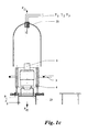
- the bell 20 is lifted in the direction of the arrow Pf1, see FIG. 1b, the preassembled vacuum interrupter 1, preassembled in a soldering jig, is inserted from its waiting place into the receiving plate 25 of the soldering place, see FIG. 1c, the bell 20 is placed on the base plate again, see Figure 1a, then the bell 20 is evacuated via the pump system connected by the suction port 24 to a value less than 2 x 10 -7 mbar.
- the vacuum interrupter 1 is then heated by applying medium-frequency energy to the excitation coil 3, the power of the coil depending on the object to be soldered being between 1.2 kW and 30 kW, the frequencies between 3.5 kHz and 1 MHz being preferred.
- the temperature inside the bell 20 and on the vacuum interrupter 1 is detected by means of the thermocouples T1, T2, T3 ... to Tn and the heating up to the soldering temperature, the soldering process and the subsequent cooling are controlled by means of a process control (not shown).
- the temperatures required for soldering the vacuum interrupter are between 700 ° C and 960 ° C.
- soldering site can be advantageous reproduce a vacuum interrupter, for example one A plurality of soldering sites on a base plate 21, such as in the Figures 3 and 4 shown schematically, are formed.
- soldering pads 2 in two parallel rows on a base plate 21 can be arranged, each soldering point having an opening 27, on the top of the base plate 21 with a susceptor 4 and one Bell 20 is equipped with thermocouples and on the underside of the Base plate 21 of the suction nozzle 24 for the connection to the high vacuum pump system is provided.
- All suction ports 24 of each soldering place 2 are with a high vacuum valve 26 for coupling and / or separating the bell 20 equipped with the high vacuum pump, the suction ports are via a further connection side 24a connected to the high vacuum pump system.
- the generator is for heating the soldering area or the vacuum interrupter 5 with the excitation coil 3 on one between the two rows of soldering sites parallel arranged rail 6 arranged in the direction of arrow Pf3.
- the generator 5 with the excitation coil 3 is on the Rail 6 is arranged to be rotatable about its vertical axis in the direction of arrow Pf4, so that the generator 5 with excitation coil 3 indiscriminately and / or in succession Approach every soldering spot in every row by moving in the direction of arrow Pf3 or Pf4.
- the manufacturing process takes place in such a way that when the bell 20 is lifted off, both the loading and unloading of the soldering area 2 is carried out with the vacuum interrupter 1 and the excitation coil 3 is moved into position or is removed from the position, and after loading and position the excitation coil, the bell 20 is placed on the soldering pad 2.
- a lifting device is also provided for positioning the excitation coil 3 in order to move the generator with the excitation coil in the direction of arrow Pf5. With the device shown in FIGS. 3 and 4, the individual soldering locations 2 can be activated one after the other and / or indiscriminately, with great flexibility in charging, soldering, decharging and cooling the vacuum interrupters to be soldered.
- the advantage is achieved that the total investment in relation to the vacuum systems and the medium-frequency or high-frequency generator can be kept small.
- the system with multiple soldering stations only requires a single ultra-high vacuum pump system in order to evacuate the individual bells 20 one after the other and / or indiscriminately. This only requires a high vacuum valve 26 between each bell and the pump system, so that each bell with its contents can be used independently.
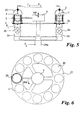
- FIGS. 5 and 6 Another possibility for increasing the production capacity is shown by the system shown schematically in FIGS. 5 and 6, in which the soldering locations 2 with glass bells 20 are arranged and formed on a disk-shaped base plate 21 in a circular ring. The system is constructed analogously to the system explained in FIGS.
- the generator 5 is arranged in the center of the base plate and can be rotated in the arrow direction Pf4 in each case by a pre-programmable angular position of the coil and, moreover, a stroke movement in the direction of the arrow Pf5 can perform.
- the heating, cooling and charging times of the soldering sites are selected so that an automatic Manufacturing process of the soldering joints can run one after the other, whereby a continuous and flexible manufacturing process is made possible.
- At least the process steps of evacuation and heating can be done via the pressure and Temperature detection of the soldering points via PC and / or PLC control be controlled and automated.
- charging is also i.e. loading and unloading with the pre-assembled vacuum interrupters included opening and closing the soldering areas by lifting and lifting the bells can be automated using robots, for example.
- the quality of the soldered and degassed vacuum interrupters can be increased and the Manufacturing costs can be reduced.
- a soldering station and a device with Soldering points for degassing and soldering vacuum interrupters in one Passage can be varied in many ways.
- a Central, oil-free forevacuum system in connection with a central high or Ultra high vacuum system can be provided as a pump system.
- each bell of a soldering station is connected to the pump system via valves.
- Decentralized ultra-high vacuum pump systems are of course also possible.
- the modular system provided according to the invention enables in a simpler manner Way to increase manufacturing capacity by adding as many Soldering places on one base plate or several base plates with several soldering places are provided, with a common ultra-high vacuum pump position is foreseeable and possibly a plurality of generators Excitation coil for the individual base plates with several soldering locations.
Landscapes
- Electric Connection Of Electric Components To Printed Circuits (AREA)
- Compressors, Vaccum Pumps And Other Relevant Systems (AREA)
- High-Tension Arc-Extinguishing Switches Without Spraying Means (AREA)
Abstract
Description
- Ofen und Charge abkühlen lassen,
- Schnellkühlung einschalten und warten bis ca. 40 bis 70° C erreicht ist.
- sehr rasche Aufwärmung der Vakuumschaltröhren durch Einsatz kleiner Einheiten, d.h. kleiner Glocken als Vakuumkammern,
- gute Kontrollmöglichkeiten der vormontierten Vakuumschaltröhre während des ganzen Lötprozesses durch Einsatz von durchsichtigen Quarzglasglocken, jede Vakuumschaltröhre ist auch visuell beobachtbar.
- Das Fließen des Lotes während des Lötprozesses der Vakuumschaltröhre ist gut zu beobachten.
- Figur 1a, b, c:
- eine Lötvorrichtung mit einem Lötplatz in einer Schnittansicht in geschlossenem, geöffnetem leeren und geöffnetem mit einer Vakuumschaltröhre bestückten Zustand;
- Figur 2:
- eine vormontierte Vakuumschaltröhre im Längsschnitt;
- Figur 3 u. 4:
- eine vertikale Schnittansicht und eine Draufsicht einer Vorrichtung mit in zwei parallelen angeordneten Lötplätzen;
- Figur 5 u. 6:
- im vertikalen Schnitt und Draufsicht eine Vorrichtung mit auf einem Kreisring angeordneten Lötplätzen;
- Figur 7 u. 8:
- einen vertikalen Schnitt durch einen Lötplatz für mehrere Vakuumschaltröhren, sowie die Draufsicht hierauf in schematisierter Form.
Eine andere Möglichkeit zur Erhöhung der Fertigungskapazität zeigt die in den Figuren 5 und 6 schematisch dargestellte Anlage, bei der die Lötplätze 2 mit Glasglocken 20 auf einer scheibenförmigen Grundplatte 21 im Kreisring angeordnet und ausgebildet sind. Die Anlage ist analog zu der in den Figuren 3 und 4 erläuterten Anlage aufgebaut, wobei hier der Generator 5 in der Mitte der Grundplatte angeordnet ist und sowohl in Pfeilrichtung Pf4 drehbar jeweils um vorprogrammierbare Winkelstellung der Spule bewegbar ist und darüber hinaus auch eine Hubbewegung in Pfeilrichtung Pf5 ausführen kann.
Claims (19)
- Vorrichtung zum Entgasen und Verlöten von vormontierten Vakuumschaltröhren in einem einzigen Lötvorgang, umfassend eine Grundplatte (21) mit mindestens einem Lötplatz (2) mit einer Durchbrechung (27) der Grundplatte für den Anschluss einer Saugpumpe und einer die Durchbrechung (27) überdeckenden auf die Grundplatte aufsetzbaren und abhebbaren Glocke (20), mit einer die Glocke (20) außenseitig umgebenden mit mittel- oder hochfrequenter Energie beaufschlagbare Erregerspule (3), mit einem Mittel- oder Hochfrequenzgenerator für die Erregerspule, und einem innerhalb der Glocke (20) angeordneten, als zylindrisches Rohrstück für die Aufnahme mindestens einer vormontierten Vakuumschaltröhre ausgebildeten Susceptor (4).
- Vorrichtung nach Anspruch 1, dadurch gekennzeichnet, dass auf der Grundplatte (21) oberhalb der Durchbrechung (27) bzw. in der Durchbrechung (27) eine gitterartige Aufnahmeplatte (25) oder Lochplatte zum Einsetzen der mindestens einen zu verlötenden vormontierten Vakuumschaltröhre (1) vorgesehen ist.
- Vorrichtung nach Anspruch 1 oder 2, dadurch gekennzeichnet, dass auf der Oberseite der Grundplatte (21) eine die Durchbrechung (27) umgebende Ringnut (28) ausgebildet ist, in der ein Dichtungsring (22) hochvakuumdicht mit der Grundplatte (21) verbunden angeordnet ist.
- Vorrichtung nach einem der Ansprüche 1 bis 3, dadurch gekennzeichnet, dass im Kopfbereich der Glocke (20) Thermoelemente (T1, T2, ... Tn) mittels einer hochvakuumdichten Durchführung (23) angeordnet sind.
- Vorrichtung nach einem der Ansprüche 1 bis 4, dadurch gekennzeichnet, dass auf der Unterseite der Grundplatte (21) an die Durchbrechung (27) ein Saugstutzen (24) hochvakuumdicht angeschlossen ist, der mit der Saugpumpe verbindbar ist.
- Vorrichtung nach einem der Ansprüche 1 bis 5, dadurch gekennzeichnet, dass Druckmesselemente (P1, P2) für den Innenraum der Glocke (20) und für die Verbindungsleitung zu der Saugpumpe vorgesehen sind.
- Vorrichtung nach einem der Ansprüche 1 bis 6, dadurch gekennzeichnet, dass der Susceptor (4) im unteren Bereich des verwendeten Frequenzspektrums aus einem weichmagnetischen Werkstoff, wie Eisen und Eisenlegierungen und/oder im höheren Bereich des verwendeten Frequenzspektrums aus hochschmelzenden Metallen und Legierungen wie Mo, W, Ta, Edelstähle und Superlegierungen aufgebaut ist.
- Vorrichtung nach einem der Ansprüche 1 bis 7, dadurch gekennzeichnet, dass der Susceptor (4) auf an der Grundplatte 21 befestigter Isolierstütze (40) beabstandet von der Grundplatte (21) angeordnet ist.
- Vorrichtung nach einem der Ansprüche 1 bis 8, dadurch gekennzeichnet, dass die Erregerspule (3) die Glocke (29) ringförmig umgibt und etwa mittig in bezug auf den Susceptor (4) angeordnet ist.
- Vorrichtung nach einem der Ansprüche 1 bis 9, dadurch gekennzeichnet, dass die Erregerspule eine Leistung von 1,2 bis 30 kW bei einer Frequenz zwischen 3,5 kHz und 1 MHz aufweist.
- Vorrichtung nach einem der Ansprüche 1 bis 10, dadurch gekennzeichnet, dass die Glocke (20) aus Quarzglas gefertigt ist.
- Vorrichtung nach einem der Ansprüche 1 bis 11, dadurch gekennzeichnet, dass die Glocke (20) mittels einer Hubvorrichtung bewegbar ist.
- Vorrichtung nach einem der Ansprüche 1 bis 12, dadurch gekennzeichnet, dass die Erregerspule bewegbar angeordnet ist.
- Vorrichtung nach einem der Ansprüche 1 bis 13, dadurch gekennzeichnet, dass bei Ausbildung der Grundplatte (21) mit mehr als einem Lötplatz (2) eine einzige Erregerspule (3) vorgesehen ist, die nacheinander und/oder wahllos zu den einzelnen Lötplätzen bewegbar ist.
- Vorrichtung nach einem der Ansprüche 1 bis 14, dadurch gekennzeichnet, dass bei Ausbildung der Grundplatte (21) mit mehr als einem Lötplatz (2) eine Saugpumpe vorgesehen ist, die über eine Saugleitung und Saugstutzen an alle Lötplätze (2) anschließbar ist, wobei jeder zu einem Lötplatz (2) führende Saugstutzen (24) mit einem Hochvakuumventil (26) ausgerüstet ist.
- Vorrichtung nach einem der Ansprüche 1 bis 15, dadurch gekennzeichnet, dass eine Grundplatte (21) mit in zwei zueinander parallelen Reihen angeordneten Lötplätzen (2) mit Durchbrechung, Glocke und Susceptor vorgesehen ist, und eine Erregerspule (3) mit Generator zwischen den Reihen auf einer Schiene parallel zu den Reihen verlaufend hin und her fahrbar angeordnet ist und eine senkrechte Hubbewegung ausführen kann.
- Vorrichtung nach einem der Ansprüche 1 bis 15, dadurch gekennzeichnet, dass eine Grundplatte (21) in Form einer Scheibe mit auf einem Kreisring angeordneten Lötplätzen (2) mit Durchbrechungen (27) der Grundplatte, Glocke (20) und Susceptor (4) vorgesehen sind und die Erregerspule mit Generator in der Mitte der Scheibe drehbar angeordnet ist und eine senkrechte Hubbewegung ausführen kann.
- Vorrichtung nach einem der Ansprüche 1 bis 17, dadurch gekennzeichnet, dass eine Lötlehre für die Aufnahme und Halterung der vormontierten Vakuumschaltröhre vorgesehen ist, die in die Aufnahmeplatte (25) des Lötplatzes (2) einsetzbar ist.
- Vorrichtung nach einem der Ansprüche 1 bis 18, dadurch gekennzeichnet, dass eine Steuerungseinrichtung für die automatische Durchführung der Prozessschritte des Bestückens der Lötplätze, evakuieren, aufheizen, und steuern der Vakuumkammern in Abhängigkeit von Temperatur und Druck bis zur Entnahme über PC und/oder SPS-Steuerung vorgesehen ist.
Applications Claiming Priority (2)
| Application Number | Priority Date | Filing Date | Title |
|---|---|---|---|
| DE10019070 | 2000-04-18 | ||
| DE10019070A DE10019070A1 (de) | 2000-04-18 | 2000-04-18 | Vorrichtung zum Entgasen und Verlöten von vormontierten Vakuumschaltröhren |
Publications (2)
| Publication Number | Publication Date |
|---|---|
| EP1148526A2 true EP1148526A2 (de) | 2001-10-24 |
| EP1148526A3 EP1148526A3 (de) | 2004-01-28 |
Family
ID=7639097
Family Applications (1)
| Application Number | Title | Priority Date | Filing Date |
|---|---|---|---|
| EP01109279A Withdrawn EP1148526A3 (de) | 2000-04-18 | 2001-04-17 | Vorrichtung zum Entgasen und Verlöten von vormontierten Vakuumschaltröhren |
Country Status (3)
| Country | Link |
|---|---|
| US (1) | US6476366B2 (de) |
| EP (1) | EP1148526A3 (de) |
| DE (1) | DE10019070A1 (de) |
Cited By (1)
| Publication number | Priority date | Publication date | Assignee | Title |
|---|---|---|---|---|
| CN103658605A (zh) * | 2013-11-26 | 2014-03-26 | 无锡日联科技有限公司 | 封闭式玻璃x射线固定无氧铜阳极靶的铸造方法及装置 |
Families Citing this family (8)
| Publication number | Priority date | Publication date | Assignee | Title |
|---|---|---|---|---|
| ATE414987T1 (de) * | 2003-12-02 | 2008-12-15 | Comet Holding Ag | Modulare röntgenröhre und verfahren zu ihrer herstellung |
| US7365289B2 (en) * | 2004-05-18 | 2008-04-29 | The United States Of America As Represented By The Department Of Health And Human Services | Production of nanostructures by curie point induction heating |
| US7789660B2 (en) * | 2005-12-07 | 2010-09-07 | Ajax Tocco Magnethermic Corporation | Furnace alignment system |
| DE102006043018A1 (de) * | 2006-09-13 | 2008-03-27 | Switchcraft Europe Gmbh | Verfahren zur verbesserten Herstellung von Vakuum-Schaltkammern |
| WO2010006830A1 (de) * | 2008-07-14 | 2010-01-21 | Siemens Aktiengesellschaft | Verfahren und vorrichtung zur herstellung von vakuumschaltröhren oder baugruppen von vakuumschaltröhren und vakuumschaltröhre |
| CN112885626B (zh) * | 2021-01-26 | 2021-11-02 | 杭州厚域科技有限公司 | 一种真空开关组件的加工方法 |
| CN114951879A (zh) * | 2022-06-08 | 2022-08-30 | 希诺股份有限公司 | 一种真空保温杯低温高效抽真空密封设备及密封工艺 |
| CN116275342A (zh) * | 2023-03-20 | 2023-06-23 | 山东天工岩土工程设备有限公司 | 一种真空感应钎焊装置及方法 |
Family Cites Families (8)
| Publication number | Priority date | Publication date | Assignee | Title |
|---|---|---|---|---|
| US2747066A (en) * | 1949-11-17 | 1956-05-22 | Porter H Brace | Heat treating apparatus |
| US2697774A (en) * | 1951-09-25 | 1954-12-21 | Standard Motor Products | Brazing machine and method |
| US2784285A (en) * | 1954-04-29 | 1957-03-05 | Western Electric Co | Brazing apparatus |
| US2876324A (en) * | 1957-11-29 | 1959-03-03 | Sylvania Electric Prod | Induction heating apparatus |
| US3045093A (en) * | 1961-01-24 | 1962-07-17 | Gen Electric | Method for constructing arc discharge devices |
| US3659552A (en) * | 1966-12-15 | 1972-05-02 | Western Electric Co | Vapor deposition apparatus |
| US4197957A (en) * | 1978-12-26 | 1980-04-15 | Gte Laboratories Incorporated | Vacuum tight assembly |
| US5753876A (en) * | 1996-05-02 | 1998-05-19 | Eaton Corporation | Clad end seal for vacuum interrupter |
-
2000
- 2000-04-18 DE DE10019070A patent/DE10019070A1/de not_active Withdrawn
-
2001
- 2001-04-17 EP EP01109279A patent/EP1148526A3/de not_active Withdrawn
- 2001-04-18 US US09/839,984 patent/US6476366B2/en not_active Expired - Fee Related
Cited By (1)
| Publication number | Priority date | Publication date | Assignee | Title |
|---|---|---|---|---|
| CN103658605A (zh) * | 2013-11-26 | 2014-03-26 | 无锡日联科技有限公司 | 封闭式玻璃x射线固定无氧铜阳极靶的铸造方法及装置 |
Also Published As
| Publication number | Publication date |
|---|---|
| EP1148526A3 (de) | 2004-01-28 |
| US6476366B2 (en) | 2002-11-05 |
| DE10019070A1 (de) | 2001-10-25 |
| US20020014472A1 (en) | 2002-02-07 |
Similar Documents
| Publication | Publication Date | Title |
|---|---|---|
| EP0419940B1 (de) | Verfahren zur Herstellung einer Vakuumschaltkammer | |
| EP1148526A2 (de) | Vorrichtung zum Entgasen und Verlöten von vormontierten Vakuumschaltröhren | |
| DE69417706T2 (de) | Vacuumschalter | |
| DE3014691A1 (de) | Vorrichtung zum sintern im vakuum und isostatischen heisspressen | |
| US2553749A (en) | Sealing fixture for the manufacture of electron discharge devices | |
| DE3437380C2 (de) | ||
| EP3140850B1 (de) | Verfahren und vorrichtung zur plasmabehandlung von substraten | |
| DE1004989B (de) | Verfahren zum Herstellen von vakuumdichten Huellen aus Metall- und Keramikteilen | |
| EP0409047B1 (de) | Verfahren zur Herstellung einer Vakuumschaltkammer | |
| WO2001035699A1 (de) | Strahlungsheizung mit einer hohen infrarot-strahlungsleistung für bearbeitungskammern | |
| DE3205501C2 (de) | ||
| DE2409818A1 (de) | Verfahren zur waermebehandlung von eisenund nichteisenmetallen | |
| DE2044277B2 (de) | Verfahren zur herstellung eines aus zwei keramikroehren bestehenden evakuierten gehaeuses | |
| WO2023001507A1 (de) | Herstellungsverfahren für ein elektrisches betriebsmittel und elektrisches betriebsmittel | |
| CH641551A5 (de) | Induktions-tiegelofen. | |
| DE2919562C2 (de) | Hochleistungskondensator | |
| AT204711B (de) | Ofen zum Schmelzen und Gießen unter Vakuum oder Schutzgasatmosphäre | |
| DE102006043018A1 (de) | Verfahren zur verbesserten Herstellung von Vakuum-Schaltkammern | |
| DD276945A1 (de) | Verfahren und vorrichtung zum fuegen und evakuieren von elektrischen geraeten | |
| WO2025067726A1 (de) | Vakuumschaltröhre zum schalten von hochspannungen und anordnung mit der vakuumschaltröhre | |
| DE970576C (de) | Verfahren zur Herstellung einer Elektronenroehre zum Anfachen ultrahochfrequenter elektrischer Schwingungen, vorzugsweise des Dezimeter- oder Zentimeterwellenlaengengebietes | |
| DE1209214B (de) | Verfahren zur Herstellung einer keramischen Elektronenroehre | |
| AT157349B (de) | Rohrförmige, vakuumdichte Durchführung durch keramische Körper. | |
| DE905518C (de) | Einrichtung zum vakuumdichten Verschmelzen von Glasroehren mit grossflaechigen Metallteilen von elektrischen Entladungsgefaessen, insbesondere mit scheibenfoermigen Durchfuehrungen fuer Hohlraumresonatoren | |
| DE1184089B (de) | Vorrichtung zum Schmelzen von Metallen |
Legal Events
| Date | Code | Title | Description |
|---|---|---|---|
| PUAI | Public reference made under article 153(3) epc to a published international application that has entered the european phase |
Free format text: ORIGINAL CODE: 0009012 |
|
| AK | Designated contracting states |
Kind code of ref document: A2 Designated state(s): AT BE CH CY DE DK ES FI FR GB GR IE IT LI LU MC NL PT SE TR |
|
| AX | Request for extension of the european patent |
Free format text: AL;LT;LV;MK;RO;SI |
|
| PUAL | Search report despatched |
Free format text: ORIGINAL CODE: 0009013 |
|
| AK | Designated contracting states |
Kind code of ref document: A3 Designated state(s): AT BE CH CY DE DK ES FI FR GB GR IE IT LI LU MC NL PT SE TR |
|
| AX | Request for extension of the european patent |
Extension state: AL LT LV MK RO SI |
|
| STAA | Information on the status of an ep patent application or granted ep patent |
Free format text: STATUS: THE APPLICATION HAS BEEN WITHDRAWN |
|
| 18W | Application withdrawn |
Effective date: 20040218 |