EP1149675A2 - Device for compacting small disposable synthetic containers - Google Patents
Device for compacting small disposable synthetic containers Download PDFInfo
- Publication number
- EP1149675A2 EP1149675A2 EP01201384A EP01201384A EP1149675A2 EP 1149675 A2 EP1149675 A2 EP 1149675A2 EP 01201384 A EP01201384 A EP 01201384A EP 01201384 A EP01201384 A EP 01201384A EP 1149675 A2 EP1149675 A2 EP 1149675A2
- Authority
- EP
- European Patent Office
- Prior art keywords
- bottle
- seat
- support
- nozzle
- supply source
- Prior art date
- Legal status (The legal status is an assumption and is not a legal conclusion. Google has not performed a legal analysis and makes no representation as to the accuracy of the status listed.)
- Withdrawn
Links
- 238000009834 vaporization Methods 0.000 claims description 2
- 230000008016 vaporization Effects 0.000 claims description 2
- 239000000463 material Substances 0.000 description 2
- XLYOFNOQVPJJNP-UHFFFAOYSA-N water Substances O XLYOFNOQVPJJNP-UHFFFAOYSA-N 0.000 description 2
- 239000000470 constituent Substances 0.000 description 1
- 238000010276 construction Methods 0.000 description 1
- 238000007598 dipping method Methods 0.000 description 1
- 238000007599 discharging Methods 0.000 description 1
- 239000000945 filler Substances 0.000 description 1
- 239000012530 fluid Substances 0.000 description 1
- 238000010438 heat treatment Methods 0.000 description 1
- 229910052500 inorganic mineral Inorganic materials 0.000 description 1
- 239000007788 liquid Substances 0.000 description 1
- 230000014759 maintenance of location Effects 0.000 description 1
- 239000011707 mineral Substances 0.000 description 1
- 229920002994 synthetic fiber Polymers 0.000 description 1
Images

Classifications
-
- B—PERFORMING OPERATIONS; TRANSPORTING
- B30—PRESSES
- B30B—PRESSES IN GENERAL
- B30B9/00—Presses specially adapted for particular purposes
- B30B9/32—Presses specially adapted for particular purposes for consolidating scrap metal or for compacting used cars
- B30B9/321—Presses specially adapted for particular purposes for consolidating scrap metal or for compacting used cars for consolidating empty containers, e.g. cans
-
- B—PERFORMING OPERATIONS; TRANSPORTING
- B29—WORKING OF PLASTICS; WORKING OF SUBSTANCES IN A PLASTIC STATE IN GENERAL
- B29B—PREPARATION OR PRETREATMENT OF THE MATERIAL TO BE SHAPED; MAKING GRANULES OR PREFORMS; RECOVERY OF PLASTICS OR OTHER CONSTITUENTS OF WASTE MATERIAL CONTAINING PLASTICS
- B29B17/00—Recovery of plastics or other constituents of waste material containing plastics
- B29B17/0026—Recovery of plastics or other constituents of waste material containing plastics by agglomeration or compacting
- B29B17/0047—Compacting complete waste articles
- B29B17/0052—Hollow articles, e.g. bottles
-
- B—PERFORMING OPERATIONS; TRANSPORTING
- B30—PRESSES
- B30B—PRESSES IN GENERAL
- B30B9/00—Presses specially adapted for particular purposes
- B30B9/30—Presses specially adapted for particular purposes for baling; Compression boxes therefor
- B30B9/3003—Details
- B30B9/3035—Means for conditioning the material to be pressed, e.g. paper shredding means
-
- B—PERFORMING OPERATIONS; TRANSPORTING
- B29—WORKING OF PLASTICS; WORKING OF SUBSTANCES IN A PLASTIC STATE IN GENERAL
- B29B—PREPARATION OR PRETREATMENT OF THE MATERIAL TO BE SHAPED; MAKING GRANULES OR PREFORMS; RECOVERY OF PLASTICS OR OTHER CONSTITUENTS OF WASTE MATERIAL CONTAINING PLASTICS
- B29B17/00—Recovery of plastics or other constituents of waste material containing plastics
- B29B17/0026—Recovery of plastics or other constituents of waste material containing plastics by agglomeration or compacting
- B29B17/0047—Compacting complete waste articles
- B29B17/0052—Hollow articles, e.g. bottles
- B29B2017/0057—Externally powered deformation tools, e.g. tools being part of relatively big non domestic installations, powered by motors
-
- B—PERFORMING OPERATIONS; TRANSPORTING
- B29—WORKING OF PLASTICS; WORKING OF SUBSTANCES IN A PLASTIC STATE IN GENERAL
- B29B—PREPARATION OR PRETREATMENT OF THE MATERIAL TO BE SHAPED; MAKING GRANULES OR PREFORMS; RECOVERY OF PLASTICS OR OTHER CONSTITUENTS OF WASTE MATERIAL CONTAINING PLASTICS
- B29B17/00—Recovery of plastics or other constituents of waste material containing plastics
- B29B17/0026—Recovery of plastics or other constituents of waste material containing plastics by agglomeration or compacting
- B29B17/0047—Compacting complete waste articles
- B29B17/0052—Hollow articles, e.g. bottles
- B29B2017/0068—Softening the hollow articles by heat and causing permanent deformation
-
- B—PERFORMING OPERATIONS; TRANSPORTING
- B29—WORKING OF PLASTICS; WORKING OF SUBSTANCES IN A PLASTIC STATE IN GENERAL
- B29K—INDEXING SCHEME ASSOCIATED WITH SUBCLASSES B29B, B29C OR B29D, RELATING TO MOULDING MATERIALS OR TO MATERIALS FOR MOULDS, REINFORCEMENTS, FILLERS OR PREFORMED PARTS, e.g. INSERTS
- B29K2067/00—Use of polyesters or derivatives thereof, as moulding material
-
- Y—GENERAL TAGGING OF NEW TECHNOLOGICAL DEVELOPMENTS; GENERAL TAGGING OF CROSS-SECTIONAL TECHNOLOGIES SPANNING OVER SEVERAL SECTIONS OF THE IPC; TECHNICAL SUBJECTS COVERED BY FORMER USPC CROSS-REFERENCE ART COLLECTIONS [XRACs] AND DIGESTS
- Y02—TECHNOLOGIES OR APPLICATIONS FOR MITIGATION OR ADAPTATION AGAINST CLIMATE CHANGE
- Y02W—CLIMATE CHANGE MITIGATION TECHNOLOGIES RELATED TO WASTEWATER TREATMENT OR WASTE MANAGEMENT
- Y02W30/00—Technologies for solid waste management
- Y02W30/50—Reuse, recycling or recovery technologies
- Y02W30/62—Plastics recycling; Rubber recycling
Definitions
- This invention relates to a device for reducing the bulk of small disposable synthetic containers, typically PET bottles and the like.
- Small disposable synthetic containers such as the said bottles, generally of between 250 and 2000 ml capacity, are currently widely used for containing fluid products, typically drinkable liquids such as mineral water.
- the main object of this invention is to provide a device able to drastically reduce the volume of such disposable bottles without requiring particular force by the user.
- a further object of the invention is to provide a bottle squashing device able to compact bottles of even considerably different capacities.
- a further object is to provide a bottle squashing device which can be used both in a domestic environment and in public locations such as bars and restaurants, and on means of transport such as trains and aircraft.
- a further object is to attain said objectives within the context of a simple, reliable, robust, compact and low-cost construction.
- the body comprises a hollow profiled body presenting an operating chamber or seat for loading the bottle, where it lies between two compactor members mutually movable along the axis of said chamber or seat, one of these acting as a support for the bottle and the other comprising, connected to a pressurized steam supply source, a delivery means to be fitted to the bottle mouth.
- Said mutual movement can be achieved by user-operated means, preferably elastic means, for example a thrust spring acting on said support, which is preferably situated below the delivery means, this latter being fixed.
- Figure 1 is a perspective view of the invention with the loading door open.
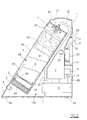
- Figure 2 is a section on the line II-II of Figure 1, but with the door closed.
- Said figures show a hollow body or casing 1 provided with non-slip support feet 99, and containing all the functional elements described hereinafter.
- Said casing is made of a convenient material, which in the illustrated example is a rigid synthetic material shaped by hot forming.
- the casing 1 is of vertically extending flattened shape, which in side view is that of a quadrilateral, and more precisely a right-angled trapezoid the inclined side of which is positioned at the front.
- the seat 98 is in the form of a portion of cylindrical wall, and is shaped and dimensioned such as to be able to receive bottles 97 of different capacities, which in the illustrated example is of 2 litres.
- said seat 98 comprises a rear base 95 inclined to the vertical, a lower transverse wall 94, an upper transverse wall 93 and a door 96, this latter being preferably transparent.
- a disc structure 92 provided with two opposing recesses, the upper one acting as the retention seat for the base of the bottle 97 and the lower one receiving the upper turns of a spring 3 which at its other end rests against said lower transverse wall 94.
- a downwardly projecting delivery nozzle 10 to be received in the neck of the bottle 97, and presenting an outer support ring for the mouth of said neck.
- Said ring 11 is also provided with small radial vent orifices 12 to enable the steam and air to escape during the collapse of the bottle 97.
- Said steam reaches the nozzle 10 via a tube 32 connected to the outlet of a steam generator of instantaneous vaporization type, this in the illustrated example being a boiler 5 with an armoured electrical resistance element.
- Said boiler 5 is connected to the delivery side of the pump 6 by the tube indicated by 66 (see Figure 2), said pump 6 dipping into the water-containing reservoir 7 via the conduit 77.
- the aforesaid elements are all contained within that compartment 132 of the casing 1 which is situated behind the seat 98, together with those accessories associated with these.
- the reservoir 7 is filled via the filler 33 provided on the right side of the casing 1, electric power to said armoured resistance element and said pump 6 being provided via the cable 31 ( Figure 2).
- Said cable 31 is wound on a support 30 provided on the base of a recess 29 in the rear wall of the casing 1.
- a small control panel comprising a main on-off switch 40, a warning lamp 44, and a pushbutton 4 for controlling steam delivery.
- significant data of the said means include the following: thrust of the spring 3 between the two configurations of Figure 2, 2-6 kg; steam pressure in boiler, 1-4 bar; steam throughput, 20-60 cc/min; maximum compacting time, 15 sec; ratio of bottle final volume to initial volume, 1:3-1:5.
- the device operates as follows.
- the resistance element of the boiler 7 is energized to raise this latter to its operating temperature.
- the disc structure After opening the door 96 the disc structure is lowered by operating with the fingers inserted into the compartment 2, and at the same time the neck of the bottle 97 is mounted over the nozzle 10, the disc structure then being released so that it rests against the base of the bottle.
- the disc structure 92 On termination of squashing, the disc structure 92 lies in its raised position, for example that shown in Figure 2, and the collapsed bottle can be extracted.
Landscapes
- Engineering & Computer Science (AREA)
- Mechanical Engineering (AREA)
- Environmental & Geological Engineering (AREA)
- Auxiliary Devices For And Details Of Packaging Control (AREA)
- Containers And Packaging Bodies Having A Special Means To Remove Contents (AREA)
- Basic Packing Technique (AREA)
Abstract
Description
Claims (15)
- A bottle squashing device, characterised by comprising a seat (98) for positioning the bottle (97) between two compactor members mutually movable along the axis of said seat, one (92) of these acting as a support for the bottle and the other comprising, connected to a pressurized steam supply source, a delivery means (10) to be inserted into the bottle mouth.
- A device as claimed in claim 1, characterised in that said delivery means is fixed and the bottle support is movable.
- A device as claimed in claim 2, characterised in that said support is moved by an elastic means.
- A device as claimed in claim 3, characterised in that said elastic means consists of a thrust spring which lies between the base wall of said seat and said support.
- A device as claimed in claim 1, characterised in that said support comprises a disc structure provided with two opposing recesses, one of which is provided to receive the base of the bottle and the other to receive one end of said thrust spring, said disc being provided with a lateral compartment for engagement by the user's fingers.
- A device as claimed in claim 5, characterised in that said compartment lies between said two recesses.
- A device as claimed in claim 1, characterised in that said delivery means comprises a nozzle to be inserted into the neck of the bottle.
- A device as claimed in claim 7, characterised in that said nozzle is provided with vent paths for the excess steam and air.
- A device as claimed in claim 8, characterised in that said vent paths comprise small orifices provided in the wall of a ring which is positioned about said nozzle in order to support the mouth of the bottle.
- A device as claimed in claim 1, characterised in that said supply source is associated with said device.
- A device as claimed in claim 11, characterised in that said supply source comprises a steam generator of instantaneous vaporization type, the inlet of which is connected to a pump with relative service reservoir.
- A device as claimed in claim 1, characterised by comprising a body of vertically extending flattened shape, which in side view has the profile of a right-angled trapezoid.
- A device as claimed in claim 12, characterised in that said seat is located in a position corresponding with said inclined side of said trapezoidal profile.
- A device as claimed in claim 13, characterised in that said seat is closed by a door.
- A device as claimed in claim 14, characterised in that said door is shaped as a portion of a cylindrical surface.
Applications Claiming Priority (2)
| Application Number | Priority Date | Filing Date | Title |
|---|---|---|---|
| ITRE000018U | 2000-04-28 | ||
| IT2000RE000018 IT251784Y1 (en) | 2000-04-28 | 2000-04-28 | DEVICE FOR THE COMPACTION OF SMALL SYNTHETIC CONTAINERS OPEN |
Publications (2)
| Publication Number | Publication Date |
|---|---|
| EP1149675A2 true EP1149675A2 (en) | 2001-10-31 |
| EP1149675A3 EP1149675A3 (en) | 2001-11-28 |
Family
ID=11453871
Family Applications (1)
| Application Number | Title | Priority Date | Filing Date |
|---|---|---|---|
| EP20010201384 Withdrawn EP1149675A3 (en) | 2000-04-28 | 2001-04-17 | Device for compacting small disposable synthetic containers |
Country Status (2)
| Country | Link |
|---|---|
| EP (1) | EP1149675A3 (en) |
| IT (1) | IT251784Y1 (en) |
Cited By (3)
| Publication number | Priority date | Publication date | Assignee | Title |
|---|---|---|---|---|
| EP1561558A3 (en) * | 2004-02-03 | 2005-11-16 | GRUSAN di SANDRIN Giannino & C. s.a.s. | Apparatus for compacting plastic containers |
| WO2009019582A1 (en) * | 2007-08-07 | 2009-02-12 | Sergio Cristofaro | Compacting device for recyclable containers |
| EP2277676A1 (en) * | 2009-07-24 | 2011-01-26 | Edmond Abergel | System for portable compacting of a container made of plastic material |
Family Cites Families (6)
| Publication number | Priority date | Publication date | Assignee | Title |
|---|---|---|---|---|
| FR2691648B1 (en) * | 1992-05-26 | 1995-09-08 | Levavasseur Jean | METHOD AND APPARATUS FOR REDUCING THE VOLUME OF PLASTIC CONTAINERS. |
| FR2692190B1 (en) * | 1992-06-16 | 1994-09-23 | Raymond Metayer | Compacting device for thermoplastic bottles. |
| WO1994021436A1 (en) * | 1993-03-17 | 1994-09-29 | Jean Levavasseur | Method for selectively recovering empty containers and equipment therefor |
| FR2712230A1 (en) * | 1993-11-04 | 1995-05-19 | Vallee Fabienne | Improvements made to plastic waste compactors, in particular household containers and packaging. |
| ES1032573Y (en) * | 1995-11-24 | 1996-11-01 | Arellano Angel Salvador | DEVICE TO REDUCE THE VOLUME OF PLASTIC MATERIAL CONTAINERS. |
| IT1302368B1 (en) * | 1998-10-12 | 2000-09-05 | Salvatore Apicella | DEVICE TO REDUCE THE VOLUME OF THERMOPLASTIC BOTTLES EMPTY BY USING STEAM |
-
2000
- 2000-04-28 IT IT2000RE000018 patent/IT251784Y1/en active
-
2001
- 2001-04-17 EP EP20010201384 patent/EP1149675A3/en not_active Withdrawn
Cited By (4)
| Publication number | Priority date | Publication date | Assignee | Title |
|---|---|---|---|---|
| EP1561558A3 (en) * | 2004-02-03 | 2005-11-16 | GRUSAN di SANDRIN Giannino & C. s.a.s. | Apparatus for compacting plastic containers |
| WO2009019582A1 (en) * | 2007-08-07 | 2009-02-12 | Sergio Cristofaro | Compacting device for recyclable containers |
| EP2277676A1 (en) * | 2009-07-24 | 2011-01-26 | Edmond Abergel | System for portable compacting of a container made of plastic material |
| FR2948312A1 (en) * | 2009-07-24 | 2011-01-28 | Edmond Abergel | PORTABLE COMPACTION SYSTEM OF A PLASTIC CONTAINER |
Also Published As
| Publication number | Publication date |
|---|---|
| EP1149675A3 (en) | 2001-11-28 |
| IT251784Y1 (en) | 2004-01-20 |
| ITRE20000018U1 (en) | 2001-10-28 |
Similar Documents
| Publication | Publication Date | Title |
|---|---|---|
| CA2544608C (en) | Mobile or portable apparatus with pressurized gas supply for preparing beverages or similar products | |
| EP2430955B1 (en) | A substance dispensing system | |
| EP0781521B1 (en) | Dispenser for a personal hygiene liquid | |
| US4570827A (en) | Liquid dispenser | |
| JP5503715B2 (en) | Beverage machine drain | |
| US3736863A (en) | Trash compactor | |
| US4349133A (en) | Dispenser and refill package | |
| US5768988A (en) | Compacting device for inorganic solid urban waste | |
| DK2651269T3 (en) | AC magnetic AND / OR DC VOLTAGE DRIVEN MACHINE FOR PRODUCTION OF ESPRESSO COFFEE AND OTHER infused DRINK AND DRINKS | |
| BG65572B1 (en) | Beverage preparing device | |
| CN1984589A (en) | Apparatus with pressurised gas supply for preparing beverages | |
| US3602136A (en) | Refuse compactor | |
| US4130054A (en) | Top loading waste compactor | |
| EP1149675A2 (en) | Device for compacting small disposable synthetic containers | |
| EP2119546B1 (en) | Thermal-electromechanical compacting apparatus for household and community use, for a vertically placed plastic material bottle and method to make the vertically placed bottle compact | |
| US3731616A (en) | Refuse compactor | |
| US6959643B1 (en) | Hydraulic trash compactor | |
| GB2470578A (en) | Waste compactor and sealer for a bin | |
| CN201102772Y (en) | Novel garbage bin | |
| EP3476769A1 (en) | Compactor device for waste collection | |
| WO2000021725A1 (en) | Apparatus for compressing empty thermoplastic bottles by steam | |
| WO2010146004A2 (en) | Device for sanitizing a solid waste collection bin | |
| EP2274145B1 (en) | Receiving-heating unit for use in bottle compression devices | |
| US924046A (en) | Liquid-soap receptacle. | |
| CA2829966A1 (en) | Device and method for compacting plastic bottles |
Legal Events
| Date | Code | Title | Description |
|---|---|---|---|
| PUAI | Public reference made under article 153(3) epc to a published international application that has entered the european phase |
Free format text: ORIGINAL CODE: 0009012 |
|
| PUAL | Search report despatched |
Free format text: ORIGINAL CODE: 0009013 |
|
| AK | Designated contracting states |
Kind code of ref document: A2 Designated state(s): AT BE CH CY DE DK ES FI FR GB GR IE IT LI LU MC NL PT SE TR |
|
| AX | Request for extension of the european patent |
Free format text: AL;LT;LV;MK;RO;SI |
|
| AK | Designated contracting states |
Kind code of ref document: A3 Designated state(s): AT BE CH CY DE DK ES FI FR GB GR IE IT LI LU MC NL PT SE TR |
|
| AX | Request for extension of the european patent |
Free format text: AL;LT;LV;MK;RO;SI |
|
| RIC1 | Information provided on ipc code assigned before grant |
Free format text: 7B 29B 17/00 A, 7B 30B 9/32 B, 7B 30B 9/30 B |
|
| AKX | Designation fees paid | ||
| REG | Reference to a national code |
Ref country code: DE Ref legal event code: 8566 |
|
| STAA | Information on the status of an ep patent application or granted ep patent |
Free format text: STATUS: THE APPLICATION IS DEEMED TO BE WITHDRAWN |
|
| 18D | Application deemed to be withdrawn |
Effective date: 20020529 |