EP1153871B1 - Auslegerstation einer Formpresse und Werkzeugsatz für eine solche Station - Google Patents
Auslegerstation einer Formpresse und Werkzeugsatz für eine solche Station Download PDFInfo
- Publication number
- EP1153871B1 EP1153871B1 EP01110728A EP01110728A EP1153871B1 EP 1153871 B1 EP1153871 B1 EP 1153871B1 EP 01110728 A EP01110728 A EP 01110728A EP 01110728 A EP01110728 A EP 01110728A EP 1153871 B1 EP1153871 B1 EP 1153871B1
- Authority
- EP
- European Patent Office
- Prior art keywords
- bars
- tool
- station
- tools
- moving slide
- Prior art date
- Legal status (The legal status is an assumption and is not a legal conclusion. Google has not performed a legal analysis and makes no representation as to the accuracy of the status listed.)
- Expired - Lifetime
Links
- 239000011111 cardboard Substances 0.000 claims abstract description 7
- 239000011087 paperboard Substances 0.000 claims description 4
- 238000000926 separation method Methods 0.000 description 7
- 238000007493 shaping process Methods 0.000 description 6
- 238000005520 cutting process Methods 0.000 description 3
- 238000009434 installation Methods 0.000 description 3
- 230000000903 blocking effect Effects 0.000 description 2
- 238000004519 manufacturing process Methods 0.000 description 2
- 239000002699 waste material Substances 0.000 description 2
- 238000003698 laser cutting Methods 0.000 description 1
- 238000003754 machining Methods 0.000 description 1
- 239000000123 paper Substances 0.000 description 1
- 230000000737 periodic effect Effects 0.000 description 1
- 238000003825 pressing Methods 0.000 description 1
- 230000003252 repetitive effect Effects 0.000 description 1
- 230000006641 stabilisation Effects 0.000 description 1
- 238000011105 stabilization Methods 0.000 description 1
- XLYOFNOQVPJJNP-UHFFFAOYSA-N water Substances O XLYOFNOQVPJJNP-UHFFFAOYSA-N 0.000 description 1
Images

Classifications
-
- B—PERFORMING OPERATIONS; TRANSPORTING
- B31—MAKING ARTICLES OF PAPER, CARDBOARD OR MATERIAL WORKED IN A MANNER ANALOGOUS TO PAPER; WORKING PAPER, CARDBOARD OR MATERIAL WORKED IN A MANNER ANALOGOUS TO PAPER
- B31F—MECHANICAL WORKING OR DEFORMATION OF PAPER, CARDBOARD OR MATERIAL WORKED IN A MANNER ANALOGOUS TO PAPER
- B31F1/00—Mechanical deformation without removing material, e.g. in combination with laminating
-
- B—PERFORMING OPERATIONS; TRANSPORTING
- B65—CONVEYING; PACKING; STORING; HANDLING THIN OR FILAMENTARY MATERIAL
- B65H—HANDLING THIN OR FILAMENTARY MATERIAL, e.g. SHEETS, WEBS, CABLES
- B65H31/00—Pile receivers
- B65H31/32—Auxiliary devices for receiving articles during removal of a completed pile
-
- B—PERFORMING OPERATIONS; TRANSPORTING
- B65—CONVEYING; PACKING; STORING; HANDLING THIN OR FILAMENTARY MATERIAL
- B65H—HANDLING THIN OR FILAMENTARY MATERIAL, e.g. SHEETS, WEBS, CABLES
- B65H2405/00—Parts for holding the handled material
- B65H2405/30—Other features of supports for sheets
- B65H2405/32—Supports for sheets partially insertable - extractable, e.g. upon sliding movement, drawer
- B65H2405/323—Cantilever finger member, e.g. reciprocating in parallel to plane of handled material
- B65H2405/3231—Cantilever during insertion but supported on both sides of the pile upon full insertion
-
- B—PERFORMING OPERATIONS; TRANSPORTING
- B65—CONVEYING; PACKING; STORING; HANDLING THIN OR FILAMENTARY MATERIAL
- B65H—HANDLING THIN OR FILAMENTARY MATERIAL, e.g. SHEETS, WEBS, CABLES
- B65H2701/00—Handled material; Storage means
- B65H2701/10—Handled articles or webs
- B65H2701/17—Nature of material
- B65H2701/176—Cardboard
- B65H2701/1762—Corrugated
Definitions
- the present invention relates to a set of tools for receiving station for a press for shaping sheets of paper or cardboard (see for example US 5,244,342), with a movable carriage and a plurality of bars which can constitute a non-stop reception grid for poses, said set of tools comprising a lower blanking tool.
- the invention also relates to a press reception station. for shaping sheets of paper or cardboard, with a mobile carriage capable of receiving a plurality of bars to constitute a reception grid non-stop poses.
- the lower blanking tool can consist of a frame for universal use, which can receive adjustable crosspieces or a grid interior made to measure, delimiting meshes whose shape substantially matches the shape of the poses.
- the bottom tool of separation of poses can also consist of a plate in which are provided, by laser cutting or water jet cutting, a plurality of openings whose periphery corresponds to that of the poses to be separated.
- the openings of the lower blanking tool constitute in general several transverse rows arranged either exactly one behind the others either with a transverse offset.
- a periodic insert a stabilization sheet is necessary. So that this insert can be performed without requiring a concomitant shutdown of the production unit, we uses a device commonly known as a non-stop grid.
- a device commonly known as a non-stop grid includes a carriage movable in the longitudinal direction of the press. Carriage has two transverse beams on which can be arranged bars intended to constitute a non-stop reception grid for poses. The bars generally have a shape similar to a cane. The head of the rod can engage in a notch of the beam furthest from the receiving station and can be fixed to it by screwing.
- the rod of the cane rests, in an area fairly close to the head of the rod, on the second cross beam of the carriage, and in an area near the other end of the rod, on a transverse roller located in the immediate vicinity of the reception of poses.
- the trolley mobile moves under the lower blanking tool and a pair of bars come to support each falling pose.
- the number of bars per installation may be higher.
- the non-stop grid temporarily receives the poses which pile up during the operations inserting.
- a preselector defines the number of cuts per pack and / or the pile height. The whole device works automatically and continues on a preprogrammed cycle.
- the ejection tools waste and the upper blanking tool are often fitted and prepared for location outside the machine, on a specially adjusted table designed for this purpose. They can therefore be prepared while the machine performs the previous work and adjusting them does not slow down the whole production.
- the bars constituting the non-stop reception grid of poses are necessarily mounted on the mobile carriage during the stopping of the machine, between two jobs.
- the operator In known shaping presses, the operator must place each bar on the mobile cart, visually aim the tool lower of separation of poses arranged in the station and to move transversely the bars so as to place two or three bars vertically each opening of the lower blanking tool. Aiming is done at an angle, in an uncomfortable position for the operator. The setting of position of all of these bars is the most laborious operation to perform between two jobs. If done incorrectly, the stacks of poses formed at reception are not straight.
- a first object of the invention is to make the operation of positioning of the bars constituting the non-stop reception grid much faster.
- a second object of the invention is to make this more reliable and independent positioning of the sighting capabilities of the operator.
- a third object of the invention is to allow tightening and quick release of the bars on the mobile carriage.
- a template tool paired with the aforementioned lower separation tool, consisting of two boards arranged on two transverse beams of the mobile carriage, with upper edges of the same profile, the edge profile upper having a plurality of slots in form of slots combined with the cross section of the bars, the arrangement of the cutouts corresponding to the transverse positions of the openings of the lower tool of separation.
- the two boards constituting the template tool are arranged on and / or against the two transverse beams of the carriage. Thanks to a centering means, they are in the correct transverse position relative to the lower blanking tool without the operator having to make additional position adjustments: a bar is set place very simply by placing its rod in two cutouts of the boards located face to face, which ensures perfect guidance of the rod and places it right of the corresponding opening of the lower installation separation tool, when the carriage advances for inserting.
- each bar is pressed at head level against the beam of the mobile cart furthest from the reception area and can be screwed into it individually.
- the carriage includes clamping means to simultaneously fix and tighten all the bars, once they are were arranged on the mobile carriage by means of the template tool.
- These means clamping devices may consist of a movable, horizontal beam and transverse, movable between a first position where it does not hamper the setting in place of the bars on the carriage and a second position where it comes in support against the head of the bars arranged on said carriage, and of a device for blocking, blocking said movable beam in said second position.
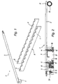
- Figure 1 shows, at the top left, a reception bar 1 non-stop poses consisting of a rod 2 of square section and a head 3.
- a reception bar 1 non-stop poses consisting of a rod 2 of square section and a head 3.
- the bar 1 are two boards 4 and 5 of general shape rectangular and elongated, constituting the template tool.
- the boards 4 and 5 On the lower edge, the boards 4 and 5 have a centering notch 6 for placing the boards 4 and 5 precisely in the machine by positioning the notches on a conjugate centering stud.
- Plates 4 and 5 have a plurality of slot cutouts on their upper edge, the profile of each cut 7, 8 corresponding exactly to the cross section of the rod 2 of the bar 1.
- the cutouts 7, 8 are arranged on the boards 4 and 5 so that if the lower blanking tool is placed in the machine, and if the boards are placed on a carriage 21 (see fig. 2) and centered, each opening of a transverse row is, seen longitudinally, opposite at least two adjacent cuts from each board, possibly three, if the width of the opening of the lower laying separator tool justified.
- the cutting of the upper edges of the boards 4, 5 can be carried out easily and very precisely by the shape manufacturer, because he has all data concerning the lower blanking tool among CAD data. These data make it possible to perfectly determine the respective position and the distance between the different bars.
- the cutting of laser slots can be performed with an accuracy of 2 tenths of millimeters.
- Figure 2 shows, in section, the boards 4 and 5 in place on the transverse beams 9 and 10 of the mobile carriage 21.
- the beams 9 and 10 have two attached flats 16, 17 and two leaf springs 18, 19 which serve as support and retaining means for boards 4 and 5.
- the centering notches 6 of the boards engage on centering pads prominent (not shown) carried by beams 9 and 10.
- the height of the boards 4 and 5 is adjusted so that the bottom of slots 7 and 8 is flush with the upper face of beams 9 and 10 or is located slightly below. When they are placed on the beams 9 and 10, the difference between the boards 4 and 5 is of the order of 150 mm.
- a lug on the head 3 of the bar 1 engages in a notch conjugate of the bar 10.
- the opposite end 11 of the rod 2 rests on a transverse roller 12, located in the immediate vicinity of the reception area for poses. Given the precision of the machining of the two plates 4 and 5, the positioning of the end 11 of the rod 2 under an opening of the tool lower of separation of installation is sufficiently precise.
- a movable transverse beam 13 removable or capable of being brought into a position where it does not hinder the positioning of the bars, comes to press all the heads 3 of the bars 1.
- the movable beam 13 carries a lining of rubber 15, so as to equalize the pressing force on all the bars 1.
- the movable beam 13 can be locked in the support position by a single or several lever locking systems per se known and shown schematically in Figure 2 by reference 20.
- FIG. 3 shows a schematic perspective view from above of the mobile carriage 21 with bars 1 individually fixed.
- each of the bars 1 is locked in position by means of screws knurled 22 which tightens the heads 3 against the beam 10.
Landscapes
- Engineering & Computer Science (AREA)
- Mechanical Engineering (AREA)
- Making Paper Articles (AREA)
- Perforating, Stamping-Out Or Severing By Means Other Than Cutting (AREA)
- Press Drives And Press Lines (AREA)
- Pile Receivers (AREA)
- Forming Counted Batches (AREA)
- Data Exchanges In Wide-Area Networks (AREA)
- Handcart (AREA)
- Press-Shaping Or Shaping Using Conveyers (AREA)
- Paper (AREA)
Claims (7)
- Werkzeugsatz für eine Auslagestation einer Stanzpresse von Papier- oder Kartonbogen, mit einem mobilen Wagen (21) und einer Mehrzahl von Stangen (1), welche einen Rechen für die Nonstop-Auslage von Nutzen bilden, wobei besagter Werkzeugsatz ein unteres Nutzentrennwerkzeug umfasst, dadurch gekennzeichnet, dass der besagte Werkzeugsatz ausserdem ein mit dem unteren Nutzentrennwerkzeug gepaartes Schablonenwerkzeug umfasst, bestehend aus zwei Platten (4, 5), welche auf zwei Querträgern (9, 10) des mobilen Wagens angeordnet werden können und obere Kanten mit gleichem Profil aufweisen, wobei dieses Profil der oberen Kante eine Mehrzahl von gezackten Aussparungen (7, 8) aufweist, deren Form dem Querschnitt der besagten Stangen (1) entspricht, wobei die Anordnung der besagten gezackten Aussparungen (7, 8) den Querpositionen der Öffnungen des unteren Nutzentrennwerkzeugs entspricht.
- Werkzeugsatz gemäss Patentanspruch 1, dadurch gekennzeichnet, dass jede Platte (4, 5) eine Zentrierkerbe (6) aufweist, die mit einem Zentrierblock eines Trägers (9, 10) des mobilen Wagens (21) zusammenwirkt.
- Werkzeugsatz gemäss Patentanspruch 1, dadurch gekennzeichnet, dass jede Platte (4, 5) einen Zentrierblock aufweist, der mit einer Zentrierkerbe eines Trägers (9, 10) des mobilen Wagens (21) zusammenwirkt.
- Auslagestation einer Stanzpresse von Papier- oder Kartonbogen, mit einem mobilen Wagen (21), der eine Mehrzahl von Stangen (1) zur Bildung eines Rechens für die Nonstop-Auslage von Nutzen aufnehmen kann, dadurch gekennzeichnet, dass der mobile Wagen (21) Mittel (16,17,18,19) zum Tragen, Halten und Zentrieren eines Schablonenwerkzeugs gemäss einem der Patenansprüche 1 bis 3 umfasst.
- Auslagestation gemäss Patentanspruch 4, dadurch gekennzeichnet, dass der mobile Wagen (21) Klemmmittel zum Befestigen und gleichzeitigen Halten von allen auf den Querträgern (9, 10) eingerichteten Stangen (1) umfasst.
- Auslagestation gemäss Patentanspruch 5, dadurch gekennzeichnet, dass die Klemmmittel einen mobilen horizontalen Querträger (13), der zwischen einer ersten Position, wo er das Einrichten der Stangen auf den Querträgern (9, 10) nicht behindert und einer zweiten Position, wo er gegen den Kopfteil (3) der auf den besagten Querträgern (9, 10) eingerichteten Stangen (1) drückt, bewegt werden kann, und einer Blockiervorrichtung (20), die den besagten mobilen Träger (13) in der besagten zweiten Position feststellt, umfassen.
- Auslagestation gemäss Patentanspruch 6, dadurch gekennzeichnet, dass der mobile Träger (13) eine Gummiverkleidung (15) auf seiner Fläche in Kontakt mit den Kopfteilen (3) der Stangen (1) hat.
Applications Claiming Priority (2)
| Application Number | Priority Date | Filing Date | Title |
|---|---|---|---|
| CH9252000 | 2000-05-11 | ||
| CH00925/00A CH694185A5 (fr) | 2000-05-11 | 2000-05-11 | Station de r'ception de presse de fa onnage et ensemble d'outils pour une telle station. |
Publications (3)
| Publication Number | Publication Date |
|---|---|
| EP1153871A2 EP1153871A2 (de) | 2001-11-14 |
| EP1153871A3 EP1153871A3 (de) | 2002-12-11 |
| EP1153871B1 true EP1153871B1 (de) | 2004-02-25 |
Family
ID=4548398
Family Applications (1)
| Application Number | Title | Priority Date | Filing Date |
|---|---|---|---|
| EP01110728A Expired - Lifetime EP1153871B1 (de) | 2000-05-11 | 2001-05-03 | Auslegerstation einer Formpresse und Werkzeugsatz für eine solche Station |
Country Status (14)
| Country | Link |
|---|---|
| US (1) | US6752586B2 (de) |
| EP (1) | EP1153871B1 (de) |
| JP (1) | JP3566228B2 (de) |
| KR (1) | KR100434569B1 (de) |
| CN (1) | CN1136094C (de) |
| AT (1) | ATE260218T1 (de) |
| AU (1) | AU781118B2 (de) |
| BR (2) | BR0002821A (de) |
| CA (1) | CA2345880C (de) |
| CH (1) | CH694185A5 (de) |
| DE (1) | DE60102097T2 (de) |
| DK (1) | DK1153871T3 (de) |
| ES (1) | ES2215811T3 (de) |
| TW (1) | TW512121B (de) |
Families Citing this family (12)
| Publication number | Priority date | Publication date | Assignee | Title |
|---|---|---|---|---|
| JP2005022868A (ja) * | 2003-06-30 | 2005-01-27 | Heidelberger Druckmas Ag | 印刷技術的な機械への枚葉紙の供給に際して主積み紙の更新中に補助積み紙を受容するための装置 |
| DE10358741A1 (de) * | 2003-12-04 | 2005-07-07 | Heidelberger Druckmaschinen Ag | Vorrichtung zum Aufnehmen eines Hilfsstapels beim Fördern von Bogen in einer drucktechnischen Maschine |
| DE102011000583A1 (de) | 2010-08-16 | 2012-02-16 | Joachim Jakob | Non-Stop-Einrichtung |
| DE202010008291U1 (de) | 2010-08-16 | 2011-02-10 | Jakob, Joachim | Non-Stop-Einrichtung |
| WO2012083430A1 (en) * | 2010-12-20 | 2012-06-28 | Novilco Inc. | Board stacking apparatus |
| TWI538871B (zh) * | 2012-03-28 | 2016-06-21 | 巴柏斯特麥克斯合資公司 | 用於轉換機的非間斷齒條裝置 |
| CN109121409B (zh) * | 2016-02-12 | 2020-04-21 | 鲍勃斯脱梅克斯股份有限公司 | 装载装置,工作站,加工机以及运送插入板材的方法 |
| TWI725713B (zh) * | 2019-02-11 | 2021-04-21 | 瑞士商巴柏斯特麥克斯合資公司 | 用於改變在片材饋送器中之片材堆疊的方法與裝置 |
| FR3093097B1 (fr) * | 2019-02-26 | 2021-04-23 | Bobst Lyon | Séparateur pour réception transitoire d’éléments en plaque entre une table élévatrice et un transporteur de sortie de paquets d’éléments |
| FR3093096B1 (fr) * | 2019-02-26 | 2021-04-23 | Bobst Lyon | Station et procédé de réception d’éléments en plaque pour une machine de fabrication d’emballage |
| CN113307079B (zh) * | 2020-02-27 | 2024-09-03 | 四川卡库机器人科技有限公司 | 叉杆式片状物料接收装置 |
| TWI763332B (zh) | 2020-03-18 | 2022-05-01 | 瑞士商巴柏斯特麥克斯合資公司 | 片材堆支撐總成及用於操作片材堆支撐總成之方法 |
Family Cites Families (18)
| Publication number | Priority date | Publication date | Assignee | Title |
|---|---|---|---|---|
| FR1532130A (fr) * | 1966-07-16 | 1968-07-05 | F F A S P A Fabbriche Fiammife | Dispositif automatique susceptible d'être monté en aval d'une trançonneuse pour recevoir des rames de feuilles abrasives en vue de les mettre en paquets |
| US3507489A (en) | 1966-09-06 | 1970-04-21 | Masson Scott Thrissell Eng Ltd | Sheet feeding apparatus |
| US4189270A (en) * | 1978-04-24 | 1980-02-19 | Georgia-Pacific Corporation | Sheet transfer and stacking apparatus |
| DE3418344A1 (de) | 1984-05-17 | 1985-11-21 | Georg Spiess Gmbh, 8906 Gersthofen | Vorrichtung zur bildung eines bogenstapels |
| DE3535113A1 (de) * | 1985-10-02 | 1987-04-23 | Jagenberg Ag | Bogenableger |
| JPS62244864A (ja) | 1986-04-17 | 1987-10-26 | Totani Giken Kogyo Kk | シ−ト材料集積装置 |
| DE3922587A1 (de) * | 1989-07-10 | 1991-01-24 | Heidelberger Druckmasch Ag | Bogenauslage an bogenverarbeitenden maschinen |
| CH682995A5 (fr) * | 1990-04-26 | 1993-12-31 | Bobst Sa | Dispositif d'interception de feuilles déposées sur le haut d'une pile dans une machine de production d'emballages. |
| JP2609754B2 (ja) | 1990-10-19 | 1997-05-14 | エス・ケイエンジニアリング株式会社 | シート積上げ装置 |
| DE4129136A1 (de) * | 1991-09-02 | 1993-03-04 | Heidelberger Druckmasch Ag | Einrichtung zum richten eines bogenstapels |
| DE4217816C2 (de) * | 1992-05-29 | 1995-01-26 | Heidelberger Druckmasch Ag | Einrichtung zur kontinuierlichen Auslage flächiger Druckprodukte |
| DE4221660C2 (de) * | 1992-07-02 | 1994-10-13 | Jagenberg Ag | Verfahren und Vorrichtung zum Stapeln von Bogen |
| CN1043874C (zh) * | 1993-02-27 | 1999-06-30 | 海德堡印刷机械股份公司 | 产生单个纸张堆垛的装置 |
| DE4442385C1 (de) * | 1994-11-29 | 1996-01-04 | Heidelberger Druckmasch Ag | Vorrichtung zur Bildung eines Stapels aus einem Bogenstrom |
| US5882175A (en) * | 1997-01-13 | 1999-03-16 | Ward Holding Company | Stacker for flexible sheets |
| DE19824694A1 (de) | 1998-06-03 | 1999-12-09 | Bhs Corr Masch & Anlagenbau | Vorrichtung zum geschuppten Ablegen von Bögen aus flexiblem Material, insbesondere Wellpappe |
| JP4189065B2 (ja) * | 1998-09-14 | 2008-12-03 | 株式会社小森コーポレーション | 枚葉輪転印刷機におけるシート受け装置 |
| US6394443B1 (en) * | 2000-11-02 | 2002-05-28 | Multifeeder Technology, Inc. | Drop table attachment for sheet feeding machine |
-
2000
- 2000-05-03 BR BR0002821-5A patent/BR0002821A/pt not_active Application Discontinuation
- 2000-05-11 CH CH00925/00A patent/CH694185A5/fr not_active IP Right Cessation
-
2001
- 2001-05-01 CA CA002345880A patent/CA2345880C/en not_active Expired - Fee Related
- 2001-05-03 AT AT01110728T patent/ATE260218T1/de not_active IP Right Cessation
- 2001-05-03 EP EP01110728A patent/EP1153871B1/de not_active Expired - Lifetime
- 2001-05-03 DE DE60102097T patent/DE60102097T2/de not_active Expired - Lifetime
- 2001-05-03 DK DK01110728T patent/DK1153871T3/da active
- 2001-05-03 ES ES01110728T patent/ES2215811T3/es not_active Expired - Lifetime
- 2001-05-09 KR KR10-2001-0025209A patent/KR100434569B1/ko not_active Expired - Fee Related
- 2001-05-10 CN CNB011214309A patent/CN1136094C/zh not_active Expired - Fee Related
- 2001-05-10 US US09/853,438 patent/US6752586B2/en not_active Expired - Fee Related
- 2001-05-10 AU AU43817/01A patent/AU781118B2/en not_active Ceased
- 2001-05-10 TW TW090111138A patent/TW512121B/zh not_active IP Right Cessation
- 2001-05-11 BR BR0101952-0A patent/BR0101952A/pt active Search and Examination
- 2001-05-11 JP JP2001141350A patent/JP3566228B2/ja not_active Expired - Fee Related
Also Published As
| Publication number | Publication date |
|---|---|
| US6752586B2 (en) | 2004-06-22 |
| CN1136094C (zh) | 2004-01-28 |
| JP2002011597A (ja) | 2002-01-15 |
| KR20010104234A (ko) | 2001-11-24 |
| CA2345880C (en) | 2004-09-14 |
| EP1153871A2 (de) | 2001-11-14 |
| DK1153871T3 (da) | 2004-07-05 |
| ES2215811T3 (es) | 2004-10-16 |
| KR100434569B1 (ko) | 2004-06-05 |
| BR0002821A (pt) | 2001-12-04 |
| JP3566228B2 (ja) | 2004-09-15 |
| CA2345880A1 (en) | 2001-11-11 |
| CH694185A5 (fr) | 2004-08-31 |
| DE60102097T2 (de) | 2005-01-05 |
| ATE260218T1 (de) | 2004-03-15 |
| DE60102097D1 (de) | 2004-04-01 |
| TW512121B (en) | 2002-12-01 |
| BR0101952A (pt) | 2001-12-18 |
| US20010053393A1 (en) | 2001-12-20 |
| CN1323691A (zh) | 2001-11-28 |
| AU4381701A (en) | 2001-11-15 |
| AU781118B2 (en) | 2005-05-05 |
| EP1153871A3 (de) | 2002-12-11 |
Similar Documents
| Publication | Publication Date | Title |
|---|---|---|
| EP1153871B1 (de) | Auslegerstation einer Formpresse und Werkzeugsatz für eine solche Station | |
| US7185797B2 (en) | Rail assembly for blanking tool insert | |
| US7698978B2 (en) | Cutting devices | |
| EP0683003B1 (de) | Vorrichtung zum Positionieren und Fixieren eines Werkzeugträgers in einer Schneidvorrichtung | |
| EP1155791B1 (de) | Schneidpresse | |
| FR2799141A1 (fr) | Dispositif de taquage pour alimenteur de documents | |
| EP0647510B1 (de) | Verfahren zum Austauschen von Stanzwerkzeugen in einer Plattenpresse sowie Vorrichtung zur Durchführung des Verfahrens | |
| EP1153716B9 (de) | Arbeitstisch für eine Schneidpresse | |
| EP1932657B1 (de) | Brailleschrift-Druckvorrichtung | |
| EP1095745A2 (de) | Verfahren zur Vorbereitung von formgebenden Werkzeugen, Einstelltisch zur Ausführung des Verfahrens und Teilesatz zur Vorbereitung eines oberen Ausbrechwerkzeuges | |
| EP0764501B1 (de) | Rahmen mit Schnellspanneinrichtung für Stanzwerkzeuge | |
| EP0683004B1 (de) | Wechselvorrichtung für die Werkzeuge einer Schneidvorrichtung | |
| EP0042244B1 (de) | Sägeführungsvorrichtung | |
| CN102092060A (zh) | 多功能木工机 | |
| US5066177A (en) | Attachment to a portable power planar | |
| AU2004222725B2 (en) | Clamping device for key duplicating machine with replaceable segmented jaws | |
| FR2498982A1 (fr) | Procede et appareillage pour preregler les outils de decoupe et d'ejection d'une presse a decouper des flans en carton | |
| CZ23631U1 (cs) | Systém upínání řezných nožů u frézovacích nástrojů pro dřevoobrábční | |
| FR2845021A1 (fr) | Presse a decouper | |
| JP2588342Y2 (ja) | 超仕上かんな盤の刃物保持具 | |
| BE423093A (de) |
Legal Events
| Date | Code | Title | Description |
|---|---|---|---|
| PUAI | Public reference made under article 153(3) epc to a published international application that has entered the european phase |
Free format text: ORIGINAL CODE: 0009012 |
|
| 17P | Request for examination filed |
Effective date: 20010505 |
|
| AK | Designated contracting states |
Kind code of ref document: A2 Designated state(s): AT BE CH CY DE DK ES FI FR GB GR IE IT LI LU MC NL PT SE TR |
|
| AX | Request for extension of the european patent |
Free format text: AL;LT;LV;MK;RO;SI |
|
| PUAL | Search report despatched |
Free format text: ORIGINAL CODE: 0009013 |
|
| AK | Designated contracting states |
Kind code of ref document: A3 Designated state(s): AT BE CH CY DE DK ES FI FR GB GR IE IT LI LU MC NL PT SE TR |
|
| AX | Request for extension of the european patent |
Free format text: AL;LT;LV;MK;RO;SI |
|
| GRAP | Despatch of communication of intention to grant a patent |
Free format text: ORIGINAL CODE: EPIDOSNIGR1 |
|
| AKX | Designation fees paid |
Designated state(s): AT BE CH CY DE DK ES FI FR GB GR IE IT LI LU MC NL PT SE TR |
|
| GRAS | Grant fee paid |
Free format text: ORIGINAL CODE: EPIDOSNIGR3 |
|
| GRAA | (expected) grant |
Free format text: ORIGINAL CODE: 0009210 |
|
| AK | Designated contracting states |
Kind code of ref document: B1 Designated state(s): AT BE CH CY DE DK ES FI FR GB GR IE IT LI LU MC NL PT SE TR |
|
| PG25 | Lapsed in a contracting state [announced via postgrant information from national office to epo] |
Ref country code: FI Free format text: LAPSE BECAUSE OF FAILURE TO SUBMIT A TRANSLATION OF THE DESCRIPTION OR TO PAY THE FEE WITHIN THE PRESCRIBED TIME-LIMIT Effective date: 20040225 Ref country code: CY Free format text: LAPSE BECAUSE OF FAILURE TO SUBMIT A TRANSLATION OF THE DESCRIPTION OR TO PAY THE FEE WITHIN THE PRESCRIBED TIME-LIMIT Effective date: 20040225 Ref country code: IE Free format text: LAPSE BECAUSE OF FAILURE TO SUBMIT A TRANSLATION OF THE DESCRIPTION OR TO PAY THE FEE WITHIN THE PRESCRIBED TIME-LIMIT Effective date: 20040225 Ref country code: TR Free format text: LAPSE BECAUSE OF FAILURE TO SUBMIT A TRANSLATION OF THE DESCRIPTION OR TO PAY THE FEE WITHIN THE PRESCRIBED TIME-LIMIT Effective date: 20040225 |
|
| REG | Reference to a national code |
Ref country code: GB Ref legal event code: FG4D Free format text: NOT ENGLISH |
|
| REG | Reference to a national code |
Ref country code: CH Ref legal event code: EP |
|
| REG | Reference to a national code |
Ref country code: IE Ref legal event code: FG4D Free format text: FRENCH |
|
| REF | Corresponds to: |
Ref document number: 60102097 Country of ref document: DE Date of ref document: 20040401 Kind code of ref document: P |
|
| GBT | Gb: translation of ep patent filed (gb section 77(6)(a)/1977) |
Effective date: 20040401 |
|
| REG | Reference to a national code |
Ref country code: SE Ref legal event code: TRGR |
|
| PG25 | Lapsed in a contracting state [announced via postgrant information from national office to epo] |
Ref country code: GR Free format text: LAPSE BECAUSE OF FAILURE TO SUBMIT A TRANSLATION OF THE DESCRIPTION OR TO PAY THE FEE WITHIN THE PRESCRIBED TIME-LIMIT Effective date: 20040525 |
|
| PG25 | Lapsed in a contracting state [announced via postgrant information from national office to epo] |
Ref country code: MC Free format text: LAPSE BECAUSE OF NON-PAYMENT OF DUE FEES Effective date: 20040531 |
|
| REG | Reference to a national code |
Ref country code: DK Ref legal event code: T3 |
|
| REG | Reference to a national code |
Ref country code: IE Ref legal event code: FD4D |
|
| REG | Reference to a national code |
Ref country code: ES Ref legal event code: FG2A Ref document number: 2215811 Country of ref document: ES Kind code of ref document: T3 |
|
| PLBE | No opposition filed within time limit |
Free format text: ORIGINAL CODE: 0009261 |
|
| STAA | Information on the status of an ep patent application or granted ep patent |
Free format text: STATUS: NO OPPOSITION FILED WITHIN TIME LIMIT |
|
| 26N | No opposition filed |
Effective date: 20041126 |
|
| PGFP | Annual fee paid to national office [announced via postgrant information from national office to epo] |
Ref country code: AT Payment date: 20070412 Year of fee payment: 7 |
|
| PGFP | Annual fee paid to national office [announced via postgrant information from national office to epo] |
Ref country code: LU Payment date: 20070511 Year of fee payment: 7 Ref country code: SE Payment date: 20070511 Year of fee payment: 7 |
|
| PGFP | Annual fee paid to national office [announced via postgrant information from national office to epo] |
Ref country code: NL Payment date: 20070515 Year of fee payment: 7 |
|
| PGFP | Annual fee paid to national office [announced via postgrant information from national office to epo] |
Ref country code: DK Payment date: 20070523 Year of fee payment: 7 |
|
| PGFP | Annual fee paid to national office [announced via postgrant information from national office to epo] |
Ref country code: GB Payment date: 20070423 Year of fee payment: 7 |
|
| PG25 | Lapsed in a contracting state [announced via postgrant information from national office to epo] |
Ref country code: PT Free format text: LAPSE BECAUSE OF NON-PAYMENT OF DUE FEES Effective date: 20040725 |
|
| PGFP | Annual fee paid to national office [announced via postgrant information from national office to epo] |
Ref country code: BE Payment date: 20070424 Year of fee payment: 7 |
|
| BERE | Be: lapsed |
Owner name: S.A. *BOBST Effective date: 20080531 |
|
| REG | Reference to a national code |
Ref country code: DK Ref legal event code: EBP |
|
| GBPC | Gb: european patent ceased through non-payment of renewal fee |
Effective date: 20080503 |
|
| PG25 | Lapsed in a contracting state [announced via postgrant information from national office to epo] |
Ref country code: NL Free format text: LAPSE BECAUSE OF NON-PAYMENT OF DUE FEES Effective date: 20081201 |
|
| PG25 | Lapsed in a contracting state [announced via postgrant information from national office to epo] |
Ref country code: AT Free format text: LAPSE BECAUSE OF NON-PAYMENT OF DUE FEES Effective date: 20080503 |
|
| PG25 | Lapsed in a contracting state [announced via postgrant information from national office to epo] |
Ref country code: BE Free format text: LAPSE BECAUSE OF NON-PAYMENT OF DUE FEES Effective date: 20080531 |
|
| PG25 | Lapsed in a contracting state [announced via postgrant information from national office to epo] |
Ref country code: DK Free format text: LAPSE BECAUSE OF NON-PAYMENT OF DUE FEES Effective date: 20080531 |
|
| PG25 | Lapsed in a contracting state [announced via postgrant information from national office to epo] |
Ref country code: GB Free format text: LAPSE BECAUSE OF NON-PAYMENT OF DUE FEES Effective date: 20080503 |
|
| PG25 | Lapsed in a contracting state [announced via postgrant information from national office to epo] |
Ref country code: LU Free format text: LAPSE BECAUSE OF NON-PAYMENT OF DUE FEES Effective date: 20080503 Ref country code: SE Free format text: LAPSE BECAUSE OF NON-PAYMENT OF DUE FEES Effective date: 20080504 |
|
| PGFP | Annual fee paid to national office [announced via postgrant information from national office to epo] |
Ref country code: DE Payment date: 20120502 Year of fee payment: 12 Ref country code: CH Payment date: 20120507 Year of fee payment: 12 |
|
| PGFP | Annual fee paid to national office [announced via postgrant information from national office to epo] |
Ref country code: FR Payment date: 20120608 Year of fee payment: 12 |
|
| PGFP | Annual fee paid to national office [announced via postgrant information from national office to epo] |
Ref country code: IT Payment date: 20120512 Year of fee payment: 12 |
|
| PGFP | Annual fee paid to national office [announced via postgrant information from national office to epo] |
Ref country code: ES Payment date: 20120607 Year of fee payment: 12 |
|
| REG | Reference to a national code |
Ref country code: CH Ref legal event code: PL |
|
| PG25 | Lapsed in a contracting state [announced via postgrant information from national office to epo] |
Ref country code: DE Free format text: LAPSE BECAUSE OF NON-PAYMENT OF DUE FEES Effective date: 20131203 Ref country code: LI Free format text: LAPSE BECAUSE OF NON-PAYMENT OF DUE FEES Effective date: 20130531 Ref country code: CH Free format text: LAPSE BECAUSE OF NON-PAYMENT OF DUE FEES Effective date: 20130531 |
|
| PG25 | Lapsed in a contracting state [announced via postgrant information from national office to epo] |
Ref country code: IT Free format text: LAPSE BECAUSE OF NON-PAYMENT OF DUE FEES Effective date: 20130503 |
|
| REG | Reference to a national code |
Ref country code: FR Ref legal event code: ST Effective date: 20140131 |
|
| REG | Reference to a national code |
Ref country code: DE Ref legal event code: R119 Ref document number: 60102097 Country of ref document: DE Effective date: 20131203 |
|
| PG25 | Lapsed in a contracting state [announced via postgrant information from national office to epo] |
Ref country code: FR Free format text: LAPSE BECAUSE OF NON-PAYMENT OF DUE FEES Effective date: 20130531 |
|
| REG | Reference to a national code |
Ref country code: ES Ref legal event code: FD2A Effective date: 20140715 |
|
| PG25 | Lapsed in a contracting state [announced via postgrant information from national office to epo] |
Ref country code: ES Free format text: LAPSE BECAUSE OF NON-PAYMENT OF DUE FEES Effective date: 20130504 |