EP1156323A1 - Sondeneinrichtung zur Aufnahme, Positionierung, Kalibrierung und/oder Wartung einer Messelektrode - Google Patents
Sondeneinrichtung zur Aufnahme, Positionierung, Kalibrierung und/oder Wartung einer Messelektrode Download PDFInfo
- Publication number
- EP1156323A1 EP1156323A1 EP01108677A EP01108677A EP1156323A1 EP 1156323 A1 EP1156323 A1 EP 1156323A1 EP 01108677 A EP01108677 A EP 01108677A EP 01108677 A EP01108677 A EP 01108677A EP 1156323 A1 EP1156323 A1 EP 1156323A1
- Authority
- EP
- European Patent Office
- Prior art keywords
- calibration
- drive
- rotary
- probe
- sealing
- Prior art date
- Legal status (The legal status is an assumption and is not a legal conclusion. Google has not performed a legal analysis and makes no representation as to the accuracy of the status listed.)
- Granted
Links
Images


Classifications
-
- G—PHYSICS
- G01—MEASURING; TESTING
- G01N—INVESTIGATING OR ANALYSING MATERIALS BY DETERMINING THEIR CHEMICAL OR PHYSICAL PROPERTIES
- G01N27/00—Investigating or analysing materials by the use of electric, electrochemical, or magnetic means
- G01N27/26—Investigating or analysing materials by the use of electric, electrochemical, or magnetic means by investigating electrochemical variables; by using electrolysis or electrophoresis
- G01N27/28—Electrolytic cell components
- G01N27/283—Means for supporting or introducing electrochemical probes
Definitions
- the invention relates to a probe device for recording, positioning, Calibration and / or maintenance of a measuring electrode to carry out of measurements in fluid media, especially for pH, redox, and conductivity ability or similar physico-chemical measurements with which in the The preamble of claim 1 features specified.
- the background and understanding of the invention is based on the basic Briefly address the problem with the specified measurements.
- pH measurements in liquids are to be discussed in more detail.
- the glass electrodes are preferably used, which at certain time intervals automatically by the addition of rinsing media, for example should be cleaned or calibrated by adding buffer solutions.
- the glass electrode has to be made of, for example, a medium process monitored in the chemical industry into one of Chamber closed in this process - the calibration chamber - within brought to the probe. This chamber is with appropriate feed and Drain lines connect to those for cleaning, flushing and calibration to be able to supply the necessary media.
- the calibration chamber must be sealed up to 100% be guaranteed to contaminate the liquid to be measured to avoid.
- sealing can be problematic be, for example, solid particles located in the process medium lie between the sealing partners and the sealing effect is disadvantageous can influence.
- the probe device should provide the highest possible security against Offer maloperation and malfunctions.
- several independent sealing barriers are in place to have certain security reserves.
- Such a probe device is now, for example, from DE 39 27 282 A1 or DE 41 40 286 A1 known.
- an electrode holder for immersion, flow and surface measurement systems in analytical chemistry shown, in which the measuring electrode between an extended measuring position and a calibration position retracted into a probe housing is displaceable by means of a lifting cylinder drive.
- a calibration chamber created by a so-called chick - in essentially by a shut-off valve - against the liquid to be measured
- the inlet and outlet channels for are internally sealed in the probe housing Flushing and calibration liquids are provided to and from this calibration chamber.
- DE 197 20 504 A1 proposes one a measuring electrode displaceable by a lifting cylinder drive of the calibration room through ceramic sealing bushings on the one hand and a formation of the displaceable inner sleeve carrying the measuring electrode from ceramic material on the other hand.
- a similar measuring electrode device is shown in DE 195 46 266 A1 of the housing, an inner sleeve and an outer sleeve made of ceramic are. About the outer sleeve is provided in the inner sleeve Measuring chamber can be sealed off. Ceramic sealing sleeves are considered to be more resistant referred to as such from conventional sealing materials.
- DE 38 12 018 C2 describes a device for measuring in particular the pH of liquids is known, in which a calibration chamber housing with a calibration chamber into the measuring medium stands.
- the opening of the calibration chamber through which the measuring medium is located can flow is via an up and down movable cover sealable.
- the supply and discharge lines for the various Calibration liquids are through channels in the calibration chamber facing surface of the closure lid is formed.
- the invention is based on the object of a probe device Generic type to improve so that a reliable seal the calibration chamber in its calibration position and safe actuation the measuring electrode when moving between its calibration position and the measuring position are guaranteed.
- the core of the registration is in Probe housing a rotary slide device is provided, which consists of a fixed sealing part and a rotating part rotatable relative thereto.
- the sealing part are an opening for the probe device, in Turned part formed the calibration chamber.
- the calibration chamber is in the measuring position and opening above each other, in the calibration position these two parts are out of overlap.
- the calibration chamber in its calibration position includes the rotating part and the sealing part plan to provide mutually adjacent sealing surfaces, the sealing partners form. These sealing surfaces are the side surfaces of the turned part and Sealing part, the facing mouth openings of the calibration chamber and exit opening surround.
- the probe device Particularly suitable for use in difficult media in which standard well-known O-ring seals or ceramic sealing bushes to fail. Processes with solid parts or soiling are examples as well as sticky or mushy process media such. B. in the food industry to call.
- a tubular probe housing 1 is made of plastic provided that in an opening not shown in a Process container is immersed in a process liquid to be measured.
- the Probe housing 1 is provided with a bottom 2 at its immersed end, the eccentrically a passage opening 3 for in the probe housing 1 arranged measuring electrode 4 - for example one typically as a purchased part added glass electrode for pH measurement - has.
- the probe housing 1 At the the bottom end is the probe housing 1 with a circumferential Provide collar 5 which is screwed to a flange 6.
- This flange 6 represents the so-called process adaptation via which the probe device can be screwed to the corresponding process container.
- a support ring 8 for a union nut 9 is on the Flange 6 screwed to the probe housing 1.
- a rotary piston drive designated as a whole by 11 on the Probe housing 1 mountable.
- the rotary piston drive 11 has one outer housing forming rotary cylinder 12 with the union nut 9 screwed and on its open side with a rotating cylinder base 10 is complete.
- a rotary piston 13 is rotatable in the rotary cylinder 12 stored, with a complex rotary piston core 14 and two protruding, occupying the working space of the rotary cylinder Rotary piston wings 15 is provided.
- a reciprocating piston 19 is axially displaceable in the lifting cylinder 18 stored, the eccentric as a piston rod a tubular Electrode holder 20 carries.
- This electrode holder 20 takes the measuring electrode 4 on and measures practically the entire axial length of the probe housing 1 and the rotary cylinder 12.
- the electrode holder 20 via a bushing 21 in the lifting cylinder base 33 to be discussed later through a bushing 21 'in the rotary piston core 14 of the rotary piston drive 11 guided axially displaceable.
- the lifting cylinder drive formed by the lifting cylinder 18 and the lifting piston 19 22 is located approximately in the middle of the axial length of probe housing 1 and Rotary cylinder 12.
- the remaining space to the process end of the Probe housing 1 is of a rotary valve device designated as a whole by 23 taken from a stationary in the probe housing 1, non-rotatable sealing part 24 and one arranged above it Rotating part 25 consists, both of which are made of a ceramic material.
- the sealing part 24 is a flat disc, which is on the bottom 2 at the bottom End of the probe housing 1 is rotatably arranged. It is axial Direction of an eccentric opening 26 for the measuring electrode 4 penetrates, which is aligned with the passage opening 3 in the bottom 2.
- the rotating part 25 is designed as a solid cylinder which has an axially continuous, with the same eccentricity as the opening 26 arranged bore which forms the calibration chamber 27 of the probe device.
- the facing mouth openings 29, 28 of the exit opening 26 or calibration chamber 27 are of flat sealing surfaces 30, 31 of the Sealing or rotating part 24, 25 surround. These two sealing surfaces 30, 31 form mutual sealing partners for sealing the calibration chamber 27 in the calibration position shown in FIG. 1 against the opening 26 entering process liquid.
- the rotation of the rotary member 25 is by Carrier 32 allows that embedded in the bottom 33 of the lifting cylinder 18 and in corresponding recesses 34 (see also FIGS. 4 to 7) in engage the top of the rotating part 25.
- the two valves 39, 40 are approximately diametrically opposite in the rotary piston core 14 arranged and are each with in or against Clockwise to the rotary piston wing 15 adjacent work rooms of the rotary piston drive 11 connected.
- Your valve body 42, 43 is each acted upon by a compression spring 44, 45 against a valve seat 46, 47.
- Both valves also have at the head end of their valve body 42, 43, respectively laterally encircling ring webs 48, 49 with a corresponding Locking groove 50 in the cover 17 in a manner to be discussed in more detail cooperate.
- a valve rod 52 is axially presented to the valve 39, which in the piston chamber of the lifting cylinder 18 protrudes and from the lifting piston 19 at the same Driving into the retracted end position is applied.
- the measuring electrode 4 is in the measuring position shown in FIGS. 2 and 3 the lift cylinder drive 22 in its fully extended position, d. H., that the piston 19 is at the lower end of its travel.
- the right valve 39 is closed and locked due to the engagement of its annular web 48 in a corresponding recess in the locking groove 50, the rotary piston drive 11 against rotation.
- the valve 40 is in its open position due to the engagement of the ring land 49 locked in the locking groove 50.
- valve 39 remains open because its ring web 48 is in the locking groove 50 is held.
- the valve 41 mentioned is used to control the pressurization of the Lift cylinder drive 22 in the extending direction. Via a compression spring 53 in doing so, its valve body 54 acts upwards in the closing direction, whereby between the valve body 54 and the cover 17 of the rotary cylinder 12 a ball 55 is inserted.
- extension position When turning the rotary lobe drive 11 from the rotary position shown in FIGS. 2 and 3 (extension position) In the calibration position shown in Fig. 1, the ball 55 runs on the inside along the lid 17, shortly after leaving the deployment position runs into a partially circumferential groove 56, whereby the valve 41st is closed. A compressed air supply to the lifting cylinder 18 is thus prevented, whereby the extension movement is "pneumatically" locked.
- Another locking is mechanical by the engagement of an edge web 57 at the opening 16 in a corresponding groove 58 on the electrode holder 59 of the electrode holder 20. This prevents that by mechanical pressure on the measuring electrode 4, the measuring tip 60th is pushed down against the sealing part 24 and destroyed.
- the electrode holder 20 is in this calibration position shown in FIG. 1 pulled with its lower end to the upper end of the calibration chamber 27, so that - in a manner to be discussed in more detail - cleaning and / or Calibrate the measuring electrode 4 in the calibration chamber 27 thus exposed can be done.
- the reverse sequence of transferring the measuring electrode 4 from the calibration position (Fig. 1) on the twisted extension in the measuring position (Fig. 2) is designed so that the valve 40 via the pneumatic Control is pressurized in the opening direction.
- the valve 40 is designed larger than the valve 39, it itself acts as a type of reciprocating piston, the counterforce of the compression spring 45 only being canceled and the valve 40 is opened when a certain minimum pneumatic pressure is present. This prevents the rotary lobe drive if the pressure is too low 11 drives off, but then in an undefined intermediate position persists.
- By opening the valve 40 the other two are now Working spaces of the rotary piston drive 11 are acted upon, valve 39 remains open and for the escape of air from the non-pressurized Working spaces.
- the ball 55 remains in during this rotational movement the partially annular groove 56 so that the compressed air supply to the lifting cylinder remains prevented via the valve 41.
- the ball 55 Upon reaching the End position and thus the extension of the measuring electrode 4 (rotary position as in Fig. 2, stroke position as in Fig. 1), the ball 55 runs out the groove 56 out, the valve 41 is opened and the compressed air is out the rotary drive via a corresponding line connection 80 in the rotary piston core 14 introduced into the upper working space of the lifting cylinder 18.
- the lifting cylinder 18 is actuated, its lifting piston 19 moves the measuring electrode 4 down and immersed them in the process (Fig. 2, 3).
- the lower end of the drain channel 66 is also approximately parallel to the surface line of the rotating part 25 extending, to the drain channel 66 deepening line groove 68th in connection, which runs over a circumferential angle of approx. 45 °.
- an extension of the inlet channel 65 is opposite End of the line groove 67 a short riser 69 provided with the calibration chamber 27 is connected. This points at its bottom End a partially annular constriction 70 at a circumferential point runs outwards in a gusset shape.
- the drain channel 66 with a short groove 71 in provided the sealing surface 31.
- the sealing part 24 is on its upward facing sealing surface 30 in Fig. 5 provided short dashed structures, namely that already mentioned Ausfahröfffiung 26 and other grooves and holes. So one is in same distance from the circumference as the line groove 67 and parallel to the circumferential line of the sealing part 24 extending line groove 72 in the Created sealing surface 30 which extends over an angle of approximately 45 °. In the extension of this line groove 72 is an axially continuous Hole 73 created. One further extends over an angular range of approximately 60 ° extending, the line groove 68 assigned, wide line groove 74 to the side of the exit opening 26. In extension of this Line groove 74 is a short stitch groove 75 from the outer periphery of the sealing part 24 provided inward.
- sealing part 24 and Rotating part 25 is the mutual assignment of sealing part 24 and Rotating part 25 can be seen in the calibration position shown in FIG. 1. So the line groove connected to the inflow channel 65 overlaps 67 in the rotating part 25 partly with the line groove 72 in the sealing part, so that the cleaning, rinsing and / or calibration liquid up to the end of the line groove remote from the inflow 72 can flow. The liquid then enters via the riser 69 the calibration chamber 27, where it swirls and the corresponding calibration and maintenance operations are carried out on the measuring electrode 4 can.
- the liquid runs in the area from the calibration chamber 27 of the gusset formed by the tapering constriction 70 into the conduit groove 74 into the sealing part 24, where it continues via the line groove 68 in the rotating part 25 into the drain channel 66 and thus further into the drain line 62 arrives.
- the line groove 74 in the sealing part and the line groove 68 in Incidentally, the rotating part forms a line, the cross section of which also changes increasing distance from the calibration chamber 27 continuously expanded.
- the rinsing liquid is drained off via a further axially parallel depression 77 on the outside of the rotating part 25, which is in a corresponding axially parallel recess 78 continues on the sealing part 24.
- the rinsing liquid thus flows into the area between the bottom 2 of the probe housing and the sealing part 24 and there also leads to a flushing and cleaning the cavities in the probe housing 1.
- the flushing liquid located under the sealing part 24 via the bore 73 upwards and arrives in the short stitch groove 71, via which it enters the drain channel 66 flows. A rinse can be seen during the measurement of the probe cavities. If there is a leak, for example, between Sealing part and rotating part 24, 25 occur, so process liquid would Mix in the rinsing liquid.
Landscapes
- Chemical & Material Sciences (AREA)
- Life Sciences & Earth Sciences (AREA)
- Health & Medical Sciences (AREA)
- Biochemistry (AREA)
- General Physics & Mathematics (AREA)
- Electrochemistry (AREA)
- Physics & Mathematics (AREA)
- Analytical Chemistry (AREA)
- Molecular Biology (AREA)
- General Health & Medical Sciences (AREA)
- Chemical Kinetics & Catalysis (AREA)
- Immunology (AREA)
- Pathology (AREA)
- Investigating Or Analyzing Materials By The Use Of Electric Means (AREA)
- Electrical Discharge Machining, Electrochemical Machining, And Combined Machining (AREA)
- Testing Or Measuring Of Semiconductors Or The Like (AREA)
- Length Measuring Devices With Unspecified Measuring Means (AREA)
Abstract
Description
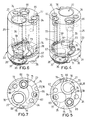
- Fig. 1
- einen Längsaxialschnitt der Sondeneinrichtung in Kalibrierstellung der Meßelektrode,
- Fig. 2
- einen Längsaxialschnitt analog Fig. 1 in der Meßstellung der Meßelektrode,
- Fig. 3
- einen Axialschnitt gemäß der Schnittlinie A-A nach Fig. 2,
- Fig. 4
- eine perspektivische Darstellung der Drehschiebereinrichtung der Sondeneinrichtung in Kalibrierstellung,
- Fig. 5
- eine schematische Draufsicht auf die Drehschiebereinrichtung gemäß Fig. 4,
- Fig. 6
- eine perspektivische Darstellung der Drehschiebereinrichtung in Meßstellung, und
- Fig. 7
- eine schematische Draufsicht auf die Drehschiebereinrichtung gemäß Fig. 6.
- Durch die Verwendung keramischer Dicht- und Drehteile 24, 25 mit absolut planen Dichtflächen 30, 31 ist eine hohe Dichtwirkung und Zuverlässigkeit der Dichteigenschaften gewährleistet.
- Neben der ersten Dichtbarriere bei den Dichtflächen 30, 31 stellen die darüberliegenden Antriebsbaugruppen des Hubzylinderantriebes 22 und Drehkolbenantriebes 11 eigenständige Dichtbarrieren mit einer internen Spülmöglichkeit und Leckage-Überwachung dar.
- Durch das praktisch unmittelbare Aufeinanderpacken von Drehkolbenantrieb 11, Hubzylinderantrieb 22 und Drehschiebereinrichtung 23 ist eine besonders kompakte Bauform der Sondeneinrichtung gewährleistet. Damit sind unterschiedlichste Prozeßadaptionen möglich.
- Die die Prozeßflüssigkeit berührenden Teile der Sondeneinrichtung sind glattflächig und damit verschmutzungsunempfindlich.
- Durch die Zwangssteuerung von Dreh- und Hubantrieb der Meßelektrode sind Fehlbetätigungen und undefinierte Zwischenstände wirkungsvoll vermieden. Dadurch zeichnet sich die Sondeneinrichtung durch eine extrem große Betriebssicherheit aus.
- Bei einer geringen oder beginnenden Undichtigkeit des Sondenhohlraumes zum Prozeß kann durch eine vermehrte interne Spülung der Hohlräume die Betriebssicherheit der Sondeneinrichtung eine gewisse Zeit aufrechterhalten werden, z. B. um einen Chargenprozeß beenden zu können.
Claims (10)
- Sondeneinrichtung zur Aufnahme, Positionierung, Kalibrierung und/oder Wartung einer Meßelektrode (4) zum Durchführen von Messungen in fluiden Medien, insbesondere für pH-, Redox-, Leitfähigkeits- und ähnliche physikalisch-chemische Messungen, mitgekennzeichnet durcheinem in das fluide Medium eintauchbaren Sondengehäuse (1),einer Halterung (20) für die Meßelektrode (4), die zwischen einer aus dem Sondengehäuse (1) herausgefahrenen Meßstellung und einer in das Sondengehäuse (1) eingefahrenen Stellung mittels eines Hubantriebes (22) der Halterung (20) verschiebbar ist,einer Kalibrierkammer (27), in der die Meßelektrode (4) in einer Kalibrierstellung gegen das zu messende Medium abgedichtet positionierbar ist, undZu- und Abflußkanälen (61, 62, 65, 66) für Spül- und Kalibrierflüssigkeiten zu und aus der Kalibrierkammer (27),eine Drehschiebereinrichtung (23) im Sondengehäuse (1),mit einem eine Ausfahröffnung (26) für die Meßelektrode (4) bildenden, feststehenden Dichtteil (24) und einem relativ dazu verdrehbaren, die Kalibrierkammer (27) aufnehmenden Drehteil (25),wobei die Kalibrierkammer (27) und die Ausfahröffnung (26) in der Meßstellung einander überdecken und in der Kalibrierstellung außer Überdeckung stehen,wobei die einander zugewandten Mündungsöffnungen (28, 29) von Kalibrierkammer (27) und Ausfahröffnung (26) in Drehteil (25) und Dichtteil (24) von gegenseitige Dichtpartner bildenden, planen Dichtflächen (30, 31) zur Abdichtung der Kalibrierkammer (27) in ihrer Kalibrierstellung umgeben sind, undeine Drehantriebseinrichtung (11), mittels derer die Halterung (20) der Meßelektrode (4) zusammen mit ihrem Hubantrieb (22) und dem Drehteil (25) der Drehschiebereinrichtung (23) zwischen der Kalibrierstellung und einer Ausfahrbereitstellung verdrehbar sind, aus der mittels des Hubantriebes (22) die Halterung (20) der Meßelektrode (4) in die Meßstellung ausfahrbar ist.
- Sondeneinrichtung nach Anspruch 1, dadurch gekennzeichnet, daß Dreh- und Dichtteil (24, 25) der Drehschiebereinrichtung (23) aus keramischen Scheiben gebildet oder ihre Dichtflächen (30, 31) mit einer keramischen Beschichtung versehen sind.
- Sondeneinrichtung nach Anspruch 1 oder 2, dadurch gekennzeichnet, daß das Dichtteil (24) gegen das Drehteil (25) axial mit einer Kraft beaufschlagt ist.
- Sondeneinrichtung nach einem der Ansprüche 1bis 3, dadurch gekennzeichnet, daß die Zu- und Abflußkanäle (65, 66) für die Spül- und Kalibrierflüssigkeiten von Bohrungen (69, 73) in sowie von Nuten (67, 68, 71, 72, 74, 75) an dem Dreh- und Dichtteil (24, 25) der Drehschiebereinrichtung (23) derart gebildet sind, daß mit der Verdrehung des Drehteils (25) relativ zum Dichtteil (24) beim Überführen der Meßelektrode (4) von der Kalibrier- in die Ausfahrbereitstellung die sondeninternen Fluidverbindungen für die Kalibrierung bzw. Spülung des Sondeninneren auf- und zusteuerbar sind.
- Sondeneinrichtung nach einem der Ansprüche 1 bis 4, dadurch gekennzeichnet, daß die Drehantriebseinrichtung von einem Drehkolbenantrieb (11) gebildet ist.
- Sondeneinrichtung nach Anspruch 5, dadurch gekennzeichnet, daß mit dem Drehkolben (13) des Drehkolbenantriebs (11) koaxial das Gehäuse (18) des als Hubzylinderantrieb (22) ausgebildeten Hubantriebes gekoppelt ist, an dem wiederum Mitnehmer (32) zur Drehbetätigung des koaxial damit liegenden Drehteils (25) der Drehschiebereinrichtung (23) angeordnet sind.
- Sondeneinrichtung nach einem der Ansprüche 1 bis 6, dadurch gekennzeichnet, daß die Drehantriebseinrichtung (11) in einem vom Sondengehäuse (1) lösbaren Drehzylinder (12) untergebracht und zusammen mit dem Hubzylinderantrieb (22) und der Halterung (20) für die Meßelektrode (4) in der Kalibrierstellung demontierbar sind.
- Sondeneinrichtung nach einem der Ansprüche 1 bis 7, dadurch gekennzeichnet, daß die Kolbenstange des Hubzylinderantriebes (22) exzentrisch zu dessen Gehäuselängsachse angeordnet ist und die Halterung (20) für die Meßelektrode (4) bildet.
- Sondeneinrichtung nach einem der Ansprüche 1 bis 8, dadurch gekennzeichnet, daß der Drehkolbenantrieb (11) und der Hubzylinderantrieb (22) jeweils durch Steuerventile (39, 40, 41) derart zwangsgesteuert sind, daß bei Betätigung eines Antriebes (11 bzw. 22) der jeweils andere Antrieb (22 bzw. 11) blockiert ist.
- Sondeneinrichtung nach Anspruch 9, dadurch gekennzeichnet, daß zur Zwangssteuerung die Steuerventile (39, 40, 41) in Abhängigkeit der Dreh- bzw. Hubstellung von Drehkolben- (11) bzw. Hubzylinderantrieb (22) mechanisch verriegelbar sind.
Applications Claiming Priority (2)
| Application Number | Priority Date | Filing Date | Title |
|---|---|---|---|
| DE10024564 | 2000-05-19 | ||
| DE10024564A DE10024564A1 (de) | 2000-05-19 | 2000-05-19 | Sondeneinrichtung zur Aufnahme, Positionierung, Kalibrierung und/oder Wartung einer Meßelektrode |
Publications (2)
| Publication Number | Publication Date |
|---|---|
| EP1156323A1 true EP1156323A1 (de) | 2001-11-21 |
| EP1156323B1 EP1156323B1 (de) | 2006-07-05 |
Family
ID=7642654
Family Applications (1)
| Application Number | Title | Priority Date | Filing Date |
|---|---|---|---|
| EP01108677A Expired - Lifetime EP1156323B1 (de) | 2000-05-19 | 2001-04-06 | Sondeneinrichtung zur Aufnahme, Positionierung, Kalibrierung und/oder Wartung einer Messelektrode |
Country Status (3)
| Country | Link |
|---|---|
| EP (1) | EP1156323B1 (de) |
| AT (1) | ATE332503T1 (de) |
| DE (2) | DE10024564A1 (de) |
Cited By (9)
| Publication number | Priority date | Publication date | Assignee | Title |
|---|---|---|---|---|
| EP1832871A2 (de) | 2006-03-07 | 2007-09-12 | Endress+Hauser Conducta Gesellschaft für Mess- und Regeltechnik mbH+Co. KG | Wechselarmatur für einen Sensor |
| DE102006018740A1 (de) * | 2006-04-22 | 2007-10-25 | Knick Elektronische Messgeräte GmbH & Co. KG | Schutzvorrichtung für eine Taucharmatur |
| AT503654B1 (de) * | 2006-10-18 | 2007-12-15 | Frings & Co Heinrich | Reaktor zur behandlung flüssiger substrate, insbesondere für zellkulturen oder mikroorganismen |
| DE102009002545A1 (de) * | 2009-04-21 | 2010-10-28 | Endress + Hauser Conducta Gesellschaft für Mess- und Regeltechnik mbH + Co. KG | Armatureinrichtung für eine Messsonde zur Messung von Prozessgrößen in einem Prozess |
| EP2278312A1 (de) * | 2009-07-16 | 2011-01-26 | Knick Elektronische Messgeräte GmbH & Co. KG | Sondeneinrichtung zur Messung von Prozessgrößen, insbesondere Schubstangenarmatur |
| CN102759553A (zh) * | 2011-04-26 | 2012-10-31 | 恩德莱斯和豪瑟尔测量及调节技术分析仪表两合公司 | 测量过程容器中包含的过程介质的被测变量的探针系统 |
| CN108066005A (zh) * | 2018-01-25 | 2018-05-25 | 鑫海合星科技(大连)有限公司 | 旋转阀体电钩 |
| CN116448839A (zh) * | 2023-04-20 | 2023-07-18 | 华北水利水电大学 | 三电极测试装置及测试方法 |
| CN116499525A (zh) * | 2023-04-28 | 2023-07-28 | 中国科学院地质与地球物理研究所 | 一种便携式不极化电极维护系统、装置及其使用方法 |
Families Citing this family (9)
| Publication number | Priority date | Publication date | Assignee | Title |
|---|---|---|---|---|
| DE10135237A1 (de) * | 2001-07-24 | 2003-02-06 | Mettler Toledo Gmbh | Vorrichtung zur Behandlung einer Messsonde sowie deren Verwendungen |
| DE10233237A1 (de) * | 2002-07-22 | 2004-02-12 | Testo Gmbh & Co | Messsonde mit einem Behälter und Verfahren zum Betrieb der Messsonde |
| DE10241833A1 (de) * | 2002-09-09 | 2004-03-18 | Mettler-Toledo Gmbh | Wechselarmatur mit einem Sensor |
| DE102005036865B4 (de) * | 2005-08-02 | 2009-02-12 | Knick Elektronische Messgeräte GmbH & Co. KG | Sondeneinrichtung zur Messung von Prozessgrößen, insbesondere physikalisch-chemischer Messgrößen, in Fluiden |
| DE102006022977B4 (de) * | 2006-05-15 | 2016-09-15 | Knick Elektronische Messgeräte GmbH & Co. KG | Sondeneinrichtung zur Messung von Prozessgrößen, insbesondere Schubstangenarmatur |
| DE102006022979A1 (de) * | 2006-05-15 | 2007-11-22 | Knick Elektronische Messgeräte GmbH & Co. KG | Sondeneinrichtung zur Messung von Prozessgrößen, insbesondere Schubstangenarmatur |
| EP1887348B1 (de) | 2006-06-23 | 2012-12-19 | Mettler-Toledo AG | Tauchrohr für eine Messsonde |
| DE102010001876A1 (de) * | 2010-02-12 | 2011-08-18 | Endress + Hauser Conducta Gesellschaft für Mess- und Regeltechnik mbH + Co. KG, 70839 | Sondeneinrichtung zum Messen einer Messgröße eines in einem Prozessbehälter enthaltenen Messmediums |
| DE102011089942A1 (de) * | 2011-12-27 | 2013-06-27 | Endress + Hauser Wetzer Gmbh + Co. Kg | Aufnahmevorrichtung für einen Messeinsatz |
Citations (5)
| Publication number | Priority date | Publication date | Assignee | Title |
|---|---|---|---|---|
| DE3643036A1 (de) * | 1986-12-17 | 1988-06-30 | Conducta Mess & Regeltech | Halterung fuer elektroden in der analytischen chemie |
| EP0372121A1 (de) * | 1988-12-02 | 1990-06-13 | Yokogawa Europe B.V. | Vorrichtung zum Festhalten eines Elektrodenhalters |
| DE4207845C1 (en) * | 1992-03-12 | 1993-09-02 | Conducta Gesellschaft Fuer Mess- Und Regeltechnik Mbh & Co, 70839 Gerlingen, De | Seal housing for process retractable analytical electrodes - allowing on=line leakage-free access to electrodes or housing seals |
| EP0753737A2 (de) * | 1995-07-08 | 1997-01-15 | Horiba, Ltd. | Vorrichtung zum Messen der Ionenkonzentration |
| DE19720504A1 (de) * | 1997-05-16 | 1998-11-19 | Conducta Endress & Hauser | Vorrichtung zur Aufnahme und Halterung einer Messelektrode |
Family Cites Families (11)
| Publication number | Priority date | Publication date | Assignee | Title |
|---|---|---|---|---|
| CH521657A (de) * | 1970-12-14 | 1972-04-15 | Proton Ag | Messwertgebereinrichtung mit herausnehmbarer Messwertgebersonde |
| CH670158A5 (de) * | 1985-05-30 | 1989-05-12 | Proton Ag | |
| DE59001999D1 (de) * | 1989-03-02 | 1993-08-26 | Ciba Geigy Ag | Vorrichtung zur erfassung chemischer ausgleichsvorgaenge in waessriger loesung. |
| DE8909903U1 (de) * | 1989-08-18 | 1989-10-12 | Conducta GmbH & Co, 7016 Gerlingen | Elektrodenhalterung für Eintauch-, Durchfluß- und Anbau-Meßsysteme in der analytischen Chemie |
| DE8909902U1 (de) * | 1989-08-18 | 1989-10-05 | Conducta GmbH & Co, 7016 Gerlingen | Elektrodenhalterung für Eintauch-, Durchfluß- und Anbau-Meßsysteme in der analytischen Chemie |
| DE8914571U1 (de) * | 1989-12-12 | 1990-03-29 | Conducta Gesellschaft für Meß- und Regeltechnik mbH & Co, 7016 Gerlingen | Vorrichtung zur (kontinuierlichen) Elektrolytzuführung und Referenzelektrodensystem |
| DE9115171U1 (de) * | 1991-12-06 | 1992-02-20 | Conducta Gesellschaft für Meß- und Regeltechnik mbH & Co, 7016 Gerlingen | Elektrodenhalterung für Eintauch-, Durchfluß- und Anbau-Meßsystem in der analytischen Chemie |
| DE9203323U1 (de) * | 1992-03-12 | 1992-04-23 | Conducta Gesellschaft für Meß- und Regeltechnik mbH & Co, 7016 Gerlingen | Elektrodenhalterung für Eintauch-, Durchfluß- und Anbau-Meßsysteme in der analytischen Chemie |
| DE4232909C2 (de) * | 1992-10-01 | 1997-05-07 | Conducta Endress & Hauser | Kopfteil eines elektrochemischen Sensors |
| DE29720248U1 (de) * | 1997-06-04 | 1998-02-12 | Mettler-Toledo Gmbh, Greifensee | Wechselarmatur |
| DE19723681C2 (de) * | 1997-06-05 | 2001-05-17 | Exner Ges Fuer Analysenmesstec | Vorrichtung zur Bestimmung von insbesondere elektrochemischen und/oder optischen Eigenschaften von Flüssigkeiten |
-
2000
- 2000-05-19 DE DE10024564A patent/DE10024564A1/de not_active Withdrawn
-
2001
- 2001-04-06 AT AT01108677T patent/ATE332503T1/de active
- 2001-04-06 DE DE50110375T patent/DE50110375D1/de not_active Expired - Lifetime
- 2001-04-06 EP EP01108677A patent/EP1156323B1/de not_active Expired - Lifetime
Patent Citations (5)
| Publication number | Priority date | Publication date | Assignee | Title |
|---|---|---|---|---|
| DE3643036A1 (de) * | 1986-12-17 | 1988-06-30 | Conducta Mess & Regeltech | Halterung fuer elektroden in der analytischen chemie |
| EP0372121A1 (de) * | 1988-12-02 | 1990-06-13 | Yokogawa Europe B.V. | Vorrichtung zum Festhalten eines Elektrodenhalters |
| DE4207845C1 (en) * | 1992-03-12 | 1993-09-02 | Conducta Gesellschaft Fuer Mess- Und Regeltechnik Mbh & Co, 70839 Gerlingen, De | Seal housing for process retractable analytical electrodes - allowing on=line leakage-free access to electrodes or housing seals |
| EP0753737A2 (de) * | 1995-07-08 | 1997-01-15 | Horiba, Ltd. | Vorrichtung zum Messen der Ionenkonzentration |
| DE19720504A1 (de) * | 1997-05-16 | 1998-11-19 | Conducta Endress & Hauser | Vorrichtung zur Aufnahme und Halterung einer Messelektrode |
Cited By (15)
| Publication number | Priority date | Publication date | Assignee | Title |
|---|---|---|---|---|
| EP1832871A3 (de) * | 2006-03-07 | 2009-04-08 | Endress+Hauser Conducta Gesellschaft für Mess- und Regeltechnik mbH+Co. KG | Wechselarmatur für einen Sensor |
| EP1832871A2 (de) | 2006-03-07 | 2007-09-12 | Endress+Hauser Conducta Gesellschaft für Mess- und Regeltechnik mbH+Co. KG | Wechselarmatur für einen Sensor |
| DE102006018740B4 (de) * | 2006-04-22 | 2011-04-14 | Knick Elektronische Messgeräte GmbH & Co. KG | Schutzvorrichtung für eine Taucharmatur |
| DE102006018740A1 (de) * | 2006-04-22 | 2007-10-25 | Knick Elektronische Messgeräte GmbH & Co. KG | Schutzvorrichtung für eine Taucharmatur |
| AT503654B1 (de) * | 2006-10-18 | 2007-12-15 | Frings & Co Heinrich | Reaktor zur behandlung flüssiger substrate, insbesondere für zellkulturen oder mikroorganismen |
| DE102009002545A1 (de) * | 2009-04-21 | 2010-10-28 | Endress + Hauser Conducta Gesellschaft für Mess- und Regeltechnik mbH + Co. KG | Armatureinrichtung für eine Messsonde zur Messung von Prozessgrößen in einem Prozess |
| US8621947B2 (en) | 2009-04-21 | 2014-01-07 | Endress + Hauser Conducta Gesellschaft für Mess—und Regeltechnik mbH + Co. KG | Assembly device for a measuring probe for measuring process variables in a process |
| EP2278312A1 (de) * | 2009-07-16 | 2011-01-26 | Knick Elektronische Messgeräte GmbH & Co. KG | Sondeneinrichtung zur Messung von Prozessgrößen, insbesondere Schubstangenarmatur |
| CN102759553A (zh) * | 2011-04-26 | 2012-10-31 | 恩德莱斯和豪瑟尔测量及调节技术分析仪表两合公司 | 测量过程容器中包含的过程介质的被测变量的探针系统 |
| CN102759553B (zh) * | 2011-04-26 | 2015-03-11 | 恩德莱斯和豪瑟尔测量及调节技术分析仪表两合公司 | 测量过程容器中包含的过程介质的被测变量的探针系统 |
| US9234860B2 (en) | 2011-04-26 | 2016-01-12 | Endress + Hauser Conducta Gesellschaft für Mess- und Regeltechnik mbH + Co. KG | Probe system for measuring a measured variable of a process medium contained in a process container |
| CN108066005A (zh) * | 2018-01-25 | 2018-05-25 | 鑫海合星科技(大连)有限公司 | 旋转阀体电钩 |
| CN108066005B (zh) * | 2018-01-25 | 2024-02-27 | 鑫海合星科技(大连)有限公司 | 旋转阀体电钩 |
| CN116448839A (zh) * | 2023-04-20 | 2023-07-18 | 华北水利水电大学 | 三电极测试装置及测试方法 |
| CN116499525A (zh) * | 2023-04-28 | 2023-07-28 | 中国科学院地质与地球物理研究所 | 一种便携式不极化电极维护系统、装置及其使用方法 |
Also Published As
| Publication number | Publication date |
|---|---|
| EP1156323B1 (de) | 2006-07-05 |
| ATE332503T1 (de) | 2006-07-15 |
| DE10024564A1 (de) | 2001-11-22 |
| DE50110375D1 (de) | 2006-08-17 |
Similar Documents
| Publication | Publication Date | Title |
|---|---|---|
| EP1156323B1 (de) | Sondeneinrichtung zur Aufnahme, Positionierung, Kalibrierung und/oder Wartung einer Messelektrode | |
| DE3126507C2 (de) | ||
| DE102012211926B4 (de) | Ventil umfassend Ventilstempel und Ventilgehäuse sowie ein Füller | |
| DE112016005328B4 (de) | Schaltventil | |
| EP0968382B1 (de) | Sitzreinigungsfähiges doppelsitzventil | |
| EP0059857A1 (de) | Reinigbares Probenentnahmeventil | |
| EP3366959B1 (de) | Ventiloberteil | |
| EP0882896B1 (de) | Wechselarmatur mit einem Sensor | |
| WO2009100921A1 (de) | Vorrichtung zur verbindung eines ventilgehäuses mit einem stellantrieb bei einem als hubventil fungierenden prozessventil | |
| DE19805478C2 (de) | 3/3-Wegeventil | |
| DE2948534A1 (de) | Absperrklappe mit leckagesicherung in rohrleitungssystemen | |
| DE19836604A1 (de) | Ventilanordnung zur Steuerung des Materialflusses in einer Beschichtungsanlage | |
| DE102006031985B4 (de) | Fluiddruckzylindervorrichtung mit Drosselventil | |
| DE19546266C2 (de) | Vorrichtung zur Aufnahme und Halterung einer Meßelektrode | |
| DE19901654C2 (de) | Eckventil mit Rosettengriff | |
| EP2203667B1 (de) | Sitzreinigungsfähiges doppelsitzventil und verfahren zur reinigung des sitzreinigungsfähigen doppelsitzventils | |
| DE102006022979A1 (de) | Sondeneinrichtung zur Messung von Prozessgrößen, insbesondere Schubstangenarmatur | |
| DE69206828T2 (de) | Betätigungsglied mit Gasfeder | |
| DE202007006784U1 (de) | Messvorrichtung zur Vermessung von Fluiden mittels einer Sonde | |
| DE102006022981B4 (de) | Sondeneinrichtung zur Messung von Prozessgrößen | |
| DE19641073C2 (de) | Druckmittelbetätigbares Ventil | |
| DE3347590C2 (de) | ||
| DE19842603C2 (de) | Sitzreinigungsfähiges Doppelsitzventil | |
| CH656228A5 (de) | Druckmesseinrichtung mit einem druckfuehler. | |
| DE29721863U1 (de) | Anordnung zum Einbau eines Meßfühlers |
Legal Events
| Date | Code | Title | Description |
|---|---|---|---|
| PUAI | Public reference made under article 153(3) epc to a published international application that has entered the european phase |
Free format text: ORIGINAL CODE: 0009012 |
|
| AK | Designated contracting states |
Kind code of ref document: A1 Designated state(s): AT BE CH CY DE DK ES FI FR GB GR IE IT LI LU MC NL PT SE TR |
|
| AX | Request for extension of the european patent |
Free format text: AL;LT;LV;MK;RO;SI |
|
| 17P | Request for examination filed |
Effective date: 20020314 |
|
| AKX | Designation fees paid |
Free format text: AT BE CH CY DE DK ES FI FR GB GR IE IT LI LU MC NL PT SE TR |
|
| 17Q | First examination report despatched |
Effective date: 20050127 |
|
| RAP1 | Party data changed (applicant data changed or rights of an application transferred) |
Owner name: KNICK ELEKTRONISCHE MESSGERAETE GMBH & CO. KG |
|
| GRAP | Despatch of communication of intention to grant a patent |
Free format text: ORIGINAL CODE: EPIDOSNIGR1 |
|
| GRAS | Grant fee paid |
Free format text: ORIGINAL CODE: EPIDOSNIGR3 |
|
| GRAA | (expected) grant |
Free format text: ORIGINAL CODE: 0009210 |
|
| AK | Designated contracting states |
Kind code of ref document: B1 Designated state(s): AT BE CH CY DE DK ES FI FR GB GR IE IT LI LU MC NL PT SE TR |
|
| PG25 | Lapsed in a contracting state [announced via postgrant information from national office to epo] |
Ref country code: IT Free format text: LAPSE BECAUSE OF FAILURE TO SUBMIT A TRANSLATION OF THE DESCRIPTION OR TO PAY THE FEE WITHIN THE PRE;WARNING: LAPSES OF ITALIAN PATENTS WITH EFFECTIVE DATE BEFORE 2007 MAY HAVE OCCURRED AT ANY TIME BEFORE 2007. THE CORRECT EFFECTIVE DATE MAY BE DIFFERENT FROM THE ONE RECORDED.SCRIBED TIME-LIMIT Effective date: 20060705 Ref country code: FI Free format text: LAPSE BECAUSE OF FAILURE TO SUBMIT A TRANSLATION OF THE DESCRIPTION OR TO PAY THE FEE WITHIN THE PRESCRIBED TIME-LIMIT Effective date: 20060705 Ref country code: IE Free format text: LAPSE BECAUSE OF FAILURE TO SUBMIT A TRANSLATION OF THE DESCRIPTION OR TO PAY THE FEE WITHIN THE PRESCRIBED TIME-LIMIT Effective date: 20060705 |
|
| REG | Reference to a national code |
Ref country code: GB Ref legal event code: FG4D Free format text: NOT ENGLISH |
|
| REG | Reference to a national code |
Ref country code: CH Ref legal event code: EP |
|
| REG | Reference to a national code |
Ref country code: IE Ref legal event code: FG4D Free format text: LANGUAGE OF EP DOCUMENT: GERMAN |
|
| REF | Corresponds to: |
Ref document number: 50110375 Country of ref document: DE Date of ref document: 20060817 Kind code of ref document: P |
|
| GBT | Gb: translation of ep patent filed (gb section 77(6)(a)/1977) |
Effective date: 20060815 |
|
| REG | Reference to a national code |
Ref country code: SE Ref legal event code: TRGR |
|
| PG25 | Lapsed in a contracting state [announced via postgrant information from national office to epo] |
Ref country code: DK Free format text: LAPSE BECAUSE OF FAILURE TO SUBMIT A TRANSLATION OF THE DESCRIPTION OR TO PAY THE FEE WITHIN THE PRESCRIBED TIME-LIMIT Effective date: 20061005 |
|
| PG25 | Lapsed in a contracting state [announced via postgrant information from national office to epo] |
Ref country code: ES Free format text: LAPSE BECAUSE OF FAILURE TO SUBMIT A TRANSLATION OF THE DESCRIPTION OR TO PAY THE FEE WITHIN THE PRESCRIBED TIME-LIMIT Effective date: 20061016 |
|
| PG25 | Lapsed in a contracting state [announced via postgrant information from national office to epo] |
Ref country code: PT Free format text: LAPSE BECAUSE OF FAILURE TO SUBMIT A TRANSLATION OF THE DESCRIPTION OR TO PAY THE FEE WITHIN THE PRESCRIBED TIME-LIMIT Effective date: 20061205 |
|
| ET | Fr: translation filed | ||
| REG | Reference to a national code |
Ref country code: IE Ref legal event code: FD4D |
|
| PLBE | No opposition filed within time limit |
Free format text: ORIGINAL CODE: 0009261 |
|
| STAA | Information on the status of an ep patent application or granted ep patent |
Free format text: STATUS: NO OPPOSITION FILED WITHIN TIME LIMIT |
|
| 26N | No opposition filed |
Effective date: 20070410 |
|
| PG25 | Lapsed in a contracting state [announced via postgrant information from national office to epo] |
Ref country code: GR Free format text: LAPSE BECAUSE OF FAILURE TO SUBMIT A TRANSLATION OF THE DESCRIPTION OR TO PAY THE FEE WITHIN THE PRESCRIBED TIME-LIMIT Effective date: 20061006 |
|
| PG25 | Lapsed in a contracting state [announced via postgrant information from national office to epo] |
Ref country code: MC Free format text: LAPSE BECAUSE OF NON-PAYMENT OF DUE FEES Effective date: 20070430 |
|
| PG25 | Lapsed in a contracting state [announced via postgrant information from national office to epo] |
Ref country code: LU Free format text: LAPSE BECAUSE OF NON-PAYMENT OF DUE FEES Effective date: 20070406 Ref country code: CY Free format text: LAPSE BECAUSE OF FAILURE TO SUBMIT A TRANSLATION OF THE DESCRIPTION OR TO PAY THE FEE WITHIN THE PRESCRIBED TIME-LIMIT Effective date: 20060705 |
|
| PG25 | Lapsed in a contracting state [announced via postgrant information from national office to epo] |
Ref country code: TR Free format text: LAPSE BECAUSE OF FAILURE TO SUBMIT A TRANSLATION OF THE DESCRIPTION OR TO PAY THE FEE WITHIN THE PRESCRIBED TIME-LIMIT Effective date: 20060705 |
|
| PGFP | Annual fee paid to national office [announced via postgrant information from national office to epo] |
Ref country code: CH Payment date: 20110316 Year of fee payment: 11 |
|
| PGFP | Annual fee paid to national office [announced via postgrant information from national office to epo] |
Ref country code: FR Payment date: 20110427 Year of fee payment: 11 Ref country code: SE Payment date: 20110419 Year of fee payment: 11 |
|
| PGFP | Annual fee paid to national office [announced via postgrant information from national office to epo] |
Ref country code: NL Payment date: 20110420 Year of fee payment: 11 Ref country code: AT Payment date: 20110317 Year of fee payment: 11 Ref country code: BE Payment date: 20110419 Year of fee payment: 11 Ref country code: GB Payment date: 20110419 Year of fee payment: 11 |
|
| PGFP | Annual fee paid to national office [announced via postgrant information from national office to epo] |
Ref country code: IT Payment date: 20110422 Year of fee payment: 11 |
|
| BERE | Be: lapsed |
Owner name: *KNICK ELEKTRONISCHE MESSGERATE G.M.B.H. & CO. K.G Effective date: 20120430 |
|
| REG | Reference to a national code |
Ref country code: NL Ref legal event code: V1 Effective date: 20121101 |
|
| REG | Reference to a national code |
Ref country code: CH Ref legal event code: PL |
|
| REG | Reference to a national code |
Ref country code: SE Ref legal event code: EUG |
|
| REG | Reference to a national code |
Ref country code: AT Ref legal event code: MM01 Ref document number: 332503 Country of ref document: AT Kind code of ref document: T Effective date: 20120406 |
|
| GBPC | Gb: european patent ceased through non-payment of renewal fee |
Effective date: 20120406 |
|
| REG | Reference to a national code |
Ref country code: FR Ref legal event code: ST Effective date: 20121228 |
|
| PG25 | Lapsed in a contracting state [announced via postgrant information from national office to epo] |
Ref country code: CH Free format text: LAPSE BECAUSE OF NON-PAYMENT OF DUE FEES Effective date: 20120430 Ref country code: BE Free format text: LAPSE BECAUSE OF NON-PAYMENT OF DUE FEES Effective date: 20120430 Ref country code: AT Free format text: LAPSE BECAUSE OF NON-PAYMENT OF DUE FEES Effective date: 20120406 Ref country code: LI Free format text: LAPSE BECAUSE OF NON-PAYMENT OF DUE FEES Effective date: 20120430 Ref country code: GB Free format text: LAPSE BECAUSE OF NON-PAYMENT OF DUE FEES Effective date: 20120406 |
|
| PG25 | Lapsed in a contracting state [announced via postgrant information from national office to epo] |
Ref country code: SE Free format text: LAPSE BECAUSE OF NON-PAYMENT OF DUE FEES Effective date: 20120407 Ref country code: IT Free format text: LAPSE BECAUSE OF NON-PAYMENT OF DUE FEES Effective date: 20120406 Ref country code: FR Free format text: LAPSE BECAUSE OF NON-PAYMENT OF DUE FEES Effective date: 20120430 |
|
| PG25 | Lapsed in a contracting state [announced via postgrant information from national office to epo] |
Ref country code: NL Free format text: LAPSE BECAUSE OF NON-PAYMENT OF DUE FEES Effective date: 20121101 |
|
| PGFP | Annual fee paid to national office [announced via postgrant information from national office to epo] |
Ref country code: DE Payment date: 20190624 Year of fee payment: 19 |
|
| REG | Reference to a national code |
Ref country code: DE Ref legal event code: R119 Ref document number: 50110375 Country of ref document: DE |
|
| PG25 | Lapsed in a contracting state [announced via postgrant information from national office to epo] |
Ref country code: DE Free format text: LAPSE BECAUSE OF NON-PAYMENT OF DUE FEES Effective date: 20201103 |