EP1156565A2 - Gasisolierte Schaltanlage mit Vakkuumschaltern - Google Patents
Gasisolierte Schaltanlage mit Vakkuumschaltern Download PDFInfo
- Publication number
- EP1156565A2 EP1156565A2 EP01104078A EP01104078A EP1156565A2 EP 1156565 A2 EP1156565 A2 EP 1156565A2 EP 01104078 A EP01104078 A EP 01104078A EP 01104078 A EP01104078 A EP 01104078A EP 1156565 A2 EP1156565 A2 EP 1156565A2
- Authority
- EP
- European Patent Office
- Prior art keywords
- insulating
- rods
- power connection
- vessel
- vacuum
- Prior art date
- Legal status (The legal status is an assumption and is not a legal conclusion. Google has not performed a legal analysis and makes no representation as to the accuracy of the status listed.)
- Withdrawn
Links
- 239000000969 carrier Substances 0.000 claims abstract description 17
- 239000011810 insulating material Substances 0.000 claims description 8
- 239000000853 adhesive Substances 0.000 claims description 4
- 230000001070 adhesive effect Effects 0.000 claims description 4
- 239000011324 bead Substances 0.000 claims description 4
- 238000001816 cooling Methods 0.000 claims description 4
- 238000000926 separation method Methods 0.000 claims description 4
- 230000000712 assembly Effects 0.000 abstract 1
- 238000000429 assembly Methods 0.000 abstract 1
- 230000002787 reinforcement Effects 0.000 description 3
- 238000009413 insulation Methods 0.000 description 2
- 238000005452 bending Methods 0.000 description 1
- 238000011161 development Methods 0.000 description 1
- 230000018109 developmental process Effects 0.000 description 1
- 230000000694 effects Effects 0.000 description 1
- 230000005684 electric field Effects 0.000 description 1
- 239000003822 epoxy resin Substances 0.000 description 1
- 230000002349 favourable effect Effects 0.000 description 1
- 239000003365 glass fiber Substances 0.000 description 1
- 238000003780 insertion Methods 0.000 description 1
- 230000037431 insertion Effects 0.000 description 1
- 238000009434 installation Methods 0.000 description 1
- 239000012528 membrane Substances 0.000 description 1
- 239000002184 metal Substances 0.000 description 1
- 229920000647 polyepoxide Polymers 0.000 description 1
Images




Classifications
-
- H—ELECTRICITY
- H01—ELECTRIC ELEMENTS
- H01H—ELECTRIC SWITCHES; RELAYS; SELECTORS; EMERGENCY PROTECTIVE DEVICES
- H01H33/00—High-tension or heavy-current switches with arc-extinguishing or arc-preventing means
- H01H33/60—Switches wherein the means for extinguishing or preventing the arc do not include separate means for obtaining or increasing flow of arc-extinguishing fluid
- H01H33/66—Vacuum switches
- H01H33/666—Operating arrangements
-
- H—ELECTRICITY
- H02—GENERATION; CONVERSION OR DISTRIBUTION OF ELECTRIC POWER
- H02B—BOARDS, SUBSTATIONS OR SWITCHING ARRANGEMENTS FOR THE SUPPLY OR DISTRIBUTION OF ELECTRIC POWER
- H02B13/00—Arrangement of switchgear in which switches are enclosed in, or structurally associated with, a casing, e.g. cubicle
- H02B13/02—Arrangement of switchgear in which switches are enclosed in, or structurally associated with, a casing, e.g. cubicle with metal casing
- H02B13/035—Gas-insulated switchgear
- H02B13/0354—Gas-insulated switchgear comprising a vacuum switch
-
- H—ELECTRICITY
- H01—ELECTRIC ELEMENTS
- H01H—ELECTRIC SWITCHES; RELAYS; SELECTORS; EMERGENCY PROTECTIVE DEVICES
- H01H33/00—High-tension or heavy-current switches with arc-extinguishing or arc-preventing means
- H01H33/60—Switches wherein the means for extinguishing or preventing the arc do not include separate means for obtaining or increasing flow of arc-extinguishing fluid
- H01H33/66—Vacuum switches
- H01H33/6606—Terminal arrangements
- H01H2033/6613—Cooling arrangements directly associated with the terminal arrangements
-
- H—ELECTRICITY
- H01—ELECTRIC ELEMENTS
- H01H—ELECTRIC SWITCHES; RELAYS; SELECTORS; EMERGENCY PROTECTIVE DEVICES
- H01H33/00—High-tension or heavy-current switches with arc-extinguishing or arc-preventing means
- H01H33/60—Switches wherein the means for extinguishing or preventing the arc do not include separate means for obtaining or increasing flow of arc-extinguishing fluid
- H01H33/66—Vacuum switches
- H01H33/666—Operating arrangements
- H01H2033/6665—Details concerning the mounting or supporting of the individual vacuum bottles
-
- H—ELECTRICITY
- H01—ELECTRIC ELEMENTS
- H01H—ELECTRIC SWITCHES; RELAYS; SELECTORS; EMERGENCY PROTECTIVE DEVICES
- H01H33/00—High-tension or heavy-current switches with arc-extinguishing or arc-preventing means
- H01H33/60—Switches wherein the means for extinguishing or preventing the arc do not include separate means for obtaining or increasing flow of arc-extinguishing fluid
- H01H33/66—Vacuum switches
- H01H33/666—Operating arrangements
- H01H2033/6667—Details concerning lever type driving rod arrangements
-
- H—ELECTRICITY
- H01—ELECTRIC ELEMENTS
- H01H—ELECTRIC SWITCHES; RELAYS; SELECTORS; EMERGENCY PROTECTIVE DEVICES
- H01H33/00—High-tension or heavy-current switches with arc-extinguishing or arc-preventing means
- H01H33/02—Details
- H01H33/022—Details particular to three-phase circuit breakers
-
- H—ELECTRICITY
- H01—ELECTRIC ELEMENTS
- H01H—ELECTRIC SWITCHES; RELAYS; SELECTORS; EMERGENCY PROTECTIVE DEVICES
- H01H33/00—High-tension or heavy-current switches with arc-extinguishing or arc-preventing means
- H01H33/02—Details
- H01H33/53—Cases; Reservoirs, tanks, piping or valves, for arc-extinguishing fluid; Accessories therefor, e.g. safety arrangements, pressure relief devices
- H01H33/56—Gas reservoirs
- H01H33/565—Gas-tight sealings for moving parts penetrating into the reservoir
-
- H—ELECTRICITY
- H01—ELECTRIC ELEMENTS
- H01H—ELECTRIC SWITCHES; RELAYS; SELECTORS; EMERGENCY PROTECTIVE DEVICES
- H01H33/00—High-tension or heavy-current switches with arc-extinguishing or arc-preventing means
- H01H33/60—Switches wherein the means for extinguishing or preventing the arc do not include separate means for obtaining or increasing flow of arc-extinguishing fluid
- H01H33/66—Vacuum switches
- H01H33/6606—Terminal arrangements
Definitions
- the invention relates to a gas-insulated switchgear, in particular in a three-pole version, according to the preamble of the first claim.
- Another gas-insulated switchgear concerns the arrangement of vacuum interrupters of circuit breakers designed as vacuum switches in one with insulating gas filled vessel and the attachment of the vacuum interrupters via insulating bodies on the Front wall of the vessel from DE 4419380 C1.
- a pole head device During every vacuum interrupter between the associated insulating support devices in the outer end area is supported radially by a pole head device, each vacuum interrupter is supported in the inner end area by a pole carrier device.
- the connection both the pole head device and the pole support device with the insulating support device takes place via first and second inclined to each other at a right angle Screw bearing.
- the invention is based, a gas-insulated switchgear according to the task Generic preamble of claim 1, by starting from a before installation in the vessel outside the vessel completely assembled vacuum switch by complete and Space-saving attachment of the vacuum switch while reducing the necessary Time required to further reduce their converted space. Further developments are formulated in the subclaims.
- this is achieved in that as an insulating body for at least one Vacuum switch at least two between the two power connection carriers of a vacuum switch insulating tubes are provided which are attached to the vessel wall (preferably on the front wall) provided pole supports hold insulated rods so that they in Longitudinal direction against the insulating pipes with simultaneous tensioning of the power connection carrier or after a non-positive connection of the power connection carrier with the insulating tubes with these are tense.
- the vessel wall receptacle elements are available as pole carriers, preferably welded bushings, threaded sleeves or nuts. There you can the insulating rods are pinned or screwed in. Should start from these pole carriers an elastic bracing of the insulating rod against the insulating tubes with simultaneous bracing the power connection carrier can be reached, so are according to an advantageous embodiment of the invention, the insulating tubes receiving the insulating tubes in the area of Vessel wall initially lying electrical connection carrier separated and take at this point of separation the pluggable on the insulating rods power connection carrier between them while the second power connection carrier on the side facing away from the pole carriers on the insulating rods is attachable. The bracing is finally carried out on the insulating rods screw-on nuts.
- the power connection carrier with the insulating tubes that hold the insulating rods by means of adhesive and / or screw connections non-positively connected, the bracing of the insulating rods against the Serve the insulating tubes back nuts that can be screwed onto the insulating rods.
- the bracing of the insulating rods in the longitudinal direction against the insulating tubes at the same time Tensioning the power connection carrier can of course also by other analog Components can be achieved.
- the pole supports can also be welded to the vessel wall There are sleeves into which the insulating rods can be inserted and by bolts or Pins can be connected to these. Based on this, bracing can take place by bolts or pins are also inserted into a hole in the free end of the insulating rods, after previously on the power connection carrier initially lying at the free end of the insulating rods pressure was applied.
- Both the insulating rods and the insulating tubes should be advantageous for the purpose of guarantee a circular heat-dissipating circulation of the insulating gas within the vessel Have cross-section.
- the insulating rods and the insulating tubes can also require rectangular paths or elliptical cross-section - except for the area that the attachment serves in the pole carriers - be formed, with which a favorable cross-sectional enlargement connected is. This increases in cooperation with that made by the invention Bracing the stiffness in the longitudinal and transverse directions, so that not only the the current forces acting but also the switching contacts during switching operations acting forces are safely absorbed.
- both the insulating tubes and the insulating rods are made of an insulating material with high mechanical strength, whereby glass fiber reinforced epoxy resin for Application can come.
- the pole supports provided on the vessel wall, to which the insulating rods are attached, also serve to stiffen the vessel wall against the pressure of the insulating gas. This Stiffening can be increased by bending the vessel wall one or more times and / or is provided with beads.
- the drivable is still Switch contact of each vacuum switch a contact force spring and a pole release spring assigned to one on the contact rod between the vessel wall and the impact body arranged at this initially lying power connection carrier are, which is formed on the side facing the vessel wall as a control electrode the electrical field and thus the insulation distance between the vessel wall and this initially minimized current connection carrier.
- a switch drive proposed to confirm the drivable Switch contacts of the three vacuum switches two in connection with the switch drive to guide gas-tight switching rods into the vessel, one of which is a switching rod isolating with the contact rod of a vacuum switch and the second switching rod via a switching transformer made of insulating material with the contact rods of the second and third vacuum switch is connected.
- This can influence it be that one vacuum switch switches before the other two vacuum switches.
- the phase of one vacuum switch is therefore ahead of the phases of the other two vacuum switches, so that overvoltages are minimized during an OFF switching operation and thus the Safety of the gas-insulated switchgear is increased.
- the number of shift rods inserted into the vessel can be reduced even further, by only one switching rod connected to the switch drive through the Vessel wall is guided, which with an existing switching transformer made of insulating material Contact rods of the three vacuum switches is connected.
- the gas-tight insertion of the switching rods into the vessel takes place via a flexible Washer (for example a rubber washer, a metal membrane or a metallic Bellows), which on the one hand with the shift rods and on the other hand with the vessel wall in connection stands and occupies a small space in the axial direction of the vacuum switch.
- a flexible Washer for example a rubber washer, a metal membrane or a metallic Bellows
- the invention is in gas-insulated switchgear both in the field of Medium voltage as well as applicable in the field of high voltage and can also such gas-insulated switchgear can be used in which only one or two vacuum switches are arranged inside the vessel filled with insulating gas.
- the through the invention intended effects are achieved even if instead of two by 180 ° Insulated pipes arranged offset from one another with the associated insulating rods, for example an arrangement of four insulating tubes, for example offset by 90 ° to one another, with the associated insulating rods.
- FIG. 1 a gas-insulated vessel 1 is seen from above in a vessel 1 filled with insulating gas Switchgear three, arranged in a horizontal line next to each other, as a vacuum switch 5,6,7 trained circuit breakers are provided.
- the drivable switch contact 11 is over the contact rod 15 with the interposition of contact elements not shown a second power connection carrier 16 in connection.
- the contact rod 15 is gas-tight by a bellows 17 by the reinforcement 18, which likewise delimits the vacuum space 8 passed through.
- the vacuum interrupters 2,3,4 are attached to the front wall 19 of the vessel 1, the outside of the vessel 1 Switch drive 20 carries.
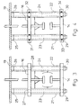
- the vacuum interrupters 2,3,4 For attaching the vacuum interrupters 2,3,4 to the front wall 19 are two parallel to the main axis of the vacuum switch and 180 ° to each other staggered insulating tubes 21, 22 receiving the power connection supports 14, 16 provided that in turn receive insulating rods 23, 24, which are provided on the front wall 19 Pole carriers 25, 26 are attached.
- Each insulating rod (23, 24) runs inside one the insulating tubes (21, 22).
- the insulating rods have a thread at each end.
- the recording the insulating rods 23, 24 through the insulating tubes 21, 22 takes place in such a way that the insulating rods 23, 24 in the longitudinal direction against the insulating tubes 21, 22 with simultaneous bracing the power connection carrier 14, 16 or after the positive connection of the power connection carrier 14, 16 with the insulating tubes 21, 22 are clamped to them.
- the insulating tubes 21, 22 have 3 shows, in the region of the power connection carrier 16, a separation point 27, 28 and take the power connector carrier 16 which can be plugged onto the insulating rods 23, 24 between themselves.
- the power connection carrier 14 has been connected to the insulating rods 23, 24 is inserted, the insulating rods 23, 24 are braced against the insulating tubes 21, 22 with simultaneous tensioning of the power connection supports 14, 16 by the insulating rods 23, 24 screw-on nuts 29,30.
- the insulating rods 23, 24 to the front wall 19 come with this design as pole supports 25, 26 welded to the front wall 19 Threaded sleeves for use, into which the insulating rods 23, 24 are screwed.
- the insulating rods 23, 24 are braced elastically against the insulating tubes 21, 22 previously also by nuts 29, 30 which can be screwed onto the insulating rods 23, 24.
- the power connection carriers 14 are here 16 non-positively connected to the insulating tubes 21, 22 by adhesive connections 31, 32 and 33, 34.
- the insulating rods 23, 24 are also attached to the front wall 19 here by pole supports 25, 26, which are designed as threaded sleeves welded to the front wall 19 are, in which the insulating rods 23,24 are screwed.
- the power connection carriers 14, 16 have cooling fins on the one hand 38 are provided and, on the other hand, conductively connected to the power connection carriers 14, 16 have standing heat sinks 39.40 which accelerate the heat-dissipating circulation serve the insulating gas.
- FIG. 2 also shows that the front wall 19 of the vessel 1 has bends 41 and beads 42, through which a stiffening of the front wall 19 is achieved and that - see also Fig. 1 - between the power connection carrier 16 of each vacuum switch 5,6,7 and the front wall 19, a striking body 43 is mounted, both the Contact force spring 44 and the pole switching spring 45 receives and on the front wall 19th facing side is designed as a control electrode 46. This is done by the control electrode 46 the insulation distance between the front wall 19 and the power connection carrier 16th minimized.
- FIG. 6 three vacuum switches 5, 6, 7 are used to actuate the drivable ones Switch contacts 11, 54, 55 of vacuum switches 5, 6, 7 only one with the switch drive 20 operatively connected shift rod 56 required. After its gastight passage through the front wall 19, again using a rubber washer 57 comes, the switching rod 56 is above a switching transformer 58 made of insulating material with each of the contact rods 15, 49, 51 in connection.
Landscapes
- Engineering & Computer Science (AREA)
- Power Engineering (AREA)
- High-Tension Arc-Extinguishing Switches Without Spraying Means (AREA)
Abstract
Description
- 1
- Gefäß
- 2,3,4
- Vakuumschaltkammern
- 5,6,7
- Vakuumschalter
- 8
- Vakuumraum
- 9
- Isolierzylinder
- 10
- feststehender Schaltkontakt
- 11,54,55
- antreibbarer Schaltkontakt
- 12
- Kondensatschirm
- 13,15,49,51
- Kontaktstangen
- 14,16
- Stromanschlußträger
- 17
- Faltenbalg
- 18
- Armierung
- 19
- Frontwand
- 20
- Schalterantrieb
- 21,22
- Isolierrohre
- 23,24
- Isolierstangen
- 25,26
- Polträger
- 27,28
- Trennstellen
- 29,30
- Muttern
- 31,32,33,34
- Klebeverbindungen
- 38
- Kühlrippen
- 39,40
- Kühlkörper
- 41
- Abbiegungen
- 42
- Sicken
- 43
- Schlagkörper
- 44
- Kontaktkraftfeder
- 45
- Polausschaltfeder
- 46
- Steuerelektrode
- 47,48,56
- Schaltstangen
- 50,58
- Schaltübertrager
- 52,53,57
- Gummischeiben
Claims (11)
- Gasisolierte Schaltanlage, insbesondere in dreipoliger Ausführung, bei der in einem mit Isoliergas gefüllten Gefäß (1) Vakuumschalter (5,6,7) für mindestens eine Phase angeordnet sind, wobei die Vakuumschalter (5,6,7) jeweils über Isolierkörper (21,22,23,24) an einer Wand (19) des Gefäßes (1) befestigt sind, dadurch gekennzeichnet, daß als Isolierkörper (21,22,23,24) für jeden Vakuumschalter (5,6,7) zumindest zwei die beiden Stromanschlußträger (14,16) eines Vakuumschalters (5,6,7) zwischen sich haltende Isolierrohre (21, 22) vorgesehen sind, die an an der Gefäßwand (19) vorgesehenen Polträgern (25, 26) befestigte Isolierstangen (23,24) halten, derart, daß diese in Längsrichtung gegen die Isolierrohre (21,22) bei gleichzeitiger Verspannung der Stromanschlußträger (14, 16) oder nach kraftschlüssiger Verbindung der Stromanschlußträger (14, 16) mit den Isolierrohren (21, 22) mit diesen verspannt sind.
- Schaltanlage nach Anspruch 1, dadurch gekennzeichnet, daß die Polträger (25,26) aus an der Gefäßwand (19) befestigten Aufnahmeelementen bestehen, an die die Isolierstangen (23,24) befestigt werden.
- Schaltanlage nach Anspruch 2, dadurch gekennzeichnet, daß die die Isolierstangen (23, 24) aufnehmenden Isolierrohre (21,22) im Bereich des der Gefäßwand (19) zunächst liegenden Stromanschlußträgers (16) getrennt sind und an dieser Trennstelle (27, 28) den auf die Isolierstangen (23,24) aufsteckbaren Stromanschlußträger (16) zwischen sich halten, während der zweite Stromanschlußträger (14) auf der den Polträgern (25, 26) abgewandten Seite auf die Isolierstangen (23,24) aufsteckbar ist und zur Verspannung der Isolierstangen (23,24) gegen die Isolierrohre (21,22) bei gleichzeitiger Verspannung der Stromanschlußträger (14,16) auf die Isolierstangen (23,24) anschraubbare Muttern (29,30) vorgesehen sind.
- Schaltanlagen nach Anspruch 2, dadurch gekennzeichnet, daß die Stromanschlußträger (14,16) mit den die Isolierstangen (23,24) aufnehmenden Isolierrohren (21, 22) durch Kleb- und oder Schraubverbindungen (31,32,33,34) kraftschlüssig verbunden sind und daß zur Verspannung der Isolierstangen (23,24) gegen die Isolierrohre (21,22) auf die Isolierstangen (23,24) aufschraubbare Muttern (29,30) vorgesehen sind.
- Schaltanlage nach Anspruch 3 oder 4, dadurch gekennzeichnet, daß sowohl die Isolierstangen (23,24) als auch die Isolierrohre (21,22) einen kreisförmigen, einen viereckförmigen oder einen elliptischen Querschnitt aufweisen.
- Schaltanlage nach Anspruch 4 oder 5, dadurch gekennzeichnet, daß sowohl die Isolierrohre (21,22) als auch die Isolierstangen (23,24) aus einem Isolierstoff hoher mechanischer Festigkeit bestehen.
- Schaltanlage nach einem der vorhergehenden Ansprüche, dadurch gekennzeichnet, daß die Stromanschlußträger (14,16) auf ihrer nach oben zugerichteten Seite mit den Stromanschlußträgern (14,16) leitend in Verbindung stehende Kühlkörper (39, 40) haben und/oder die Oberfläche vergrößernde Kühlrippen (38) aufweisen.
- Schaltanlage nach einem der vorhergehenden Ansprüche, dadurch gekennzeichnet, daß die Gefäßwand (19) mindestens einmal abgebogen ist und/oder mit Sicken (42) versehen ist.
- Schaltanlage nach einem der vorhergehenden Ansprüche, dadurch gekennzeichnet, daß dem antreibbaren Schaltkontakt (11,54,55) eines jeden Vakuumschalters (5,6,7) eine Kontaktkraftfeder (44) sowie eine Polausschaltfeder (45) zugeordnet ist, die an einem auf der Kontaktstange (15) zwischen der Gefäßwand (19) und dem dieser zunächst liegenden Stromanschlußträger (16) angeordneten Schlagkörper (43) gelagert sind, der auf der der Gefäßwand (19) zugerichteten Seite als Steuerelektrode (46) ausgebildet ist.
- Schaltanlage nach einem der vorhergehenden Ansprüche, dadurch gekennzeichnet, daß die Schaltanlage dreiphasig ausgebildet ist und außerhalb des Gefäßes (1) einen Schalterantrieb (20) trägt und daß zur Betätigung der antreibbaren Schaltkontakte (11,54,55) der drei Vakuumschalter (5,6,7) zwei mit dem Schalterantrieb (20) in Verbindung stehende Schaltstangen (47,48) durch die Gefäßwand (19) gasdicht geführt sind, von denen die eine Schaltstange (47) isolierend mit der Kontaktstange (49) eines Vakuumschalters (7) und die zweite Schaltstange (48) über einen aus Isolierstoff bestehenden Schaltübertrager (50) mit den Kontaktstangen (15,51) des zweiten (5) und dritten (6) Vakuumschalters in Verbindung steht.
- Schaltanlage nach einem der Ansprüche 1 bis 9, dadurch gekennzeichnet, daß die Schaltanlage dreiphasig ausgebildet ist und außerhalb des Gefäßes (1) einen Schalterantrieb (20) trägt und daß zur Betätigung der antreibbaren Schaltkontakte (11,54,55) der drei Vakuumschalter (5,6,7) eine mit dem Schalterantrieb (20) in Verbindung stehende Schaltstange (51) durch die Gefäßwand (19) gasdicht geführt ist, die über einen aus Isolierstoff bestehenden Schaltübertrager (58) mit den Kontaktstangen (15,49,51) der Vakuumschalter (5, 6, 7) verbunden ist.
Applications Claiming Priority (2)
| Application Number | Priority Date | Filing Date | Title |
|---|---|---|---|
| DE2000124356 DE10024356C1 (de) | 2000-05-17 | 2000-05-17 | Gasisolierte Schaltanlage mit Vakuumschaltern |
| DE10024356 | 2000-05-17 |
Publications (2)
| Publication Number | Publication Date |
|---|---|
| EP1156565A2 true EP1156565A2 (de) | 2001-11-21 |
| EP1156565A3 EP1156565A3 (de) | 2004-05-12 |
Family
ID=7642514
Family Applications (1)
| Application Number | Title | Priority Date | Filing Date |
|---|---|---|---|
| EP01104078A Withdrawn EP1156565A3 (de) | 2000-05-17 | 2001-02-21 | Gasisolierte Schaltanlage mit Vakkuumschaltern |
Country Status (3)
| Country | Link |
|---|---|
| EP (1) | EP1156565A3 (de) |
| CN (1) | CN1230955C (de) |
| DE (1) | DE10024356C1 (de) |
Cited By (2)
| Publication number | Priority date | Publication date | Assignee | Title |
|---|---|---|---|---|
| EP2015331A2 (de) | 2007-07-09 | 2009-01-14 | Ormazabal Distribucion Primaria, S.A. | Antriebsvorrichtung für einer Vakuumlastschalter mit Vorrichtung zum Vermeiden von Kontaktschwingungen |
| CN117767163A (zh) * | 2023-11-10 | 2024-03-26 | 珠海康晋电气股份有限公司 | 一种常压密封空气绝缘环网柜 |
Families Citing this family (4)
| Publication number | Priority date | Publication date | Assignee | Title |
|---|---|---|---|---|
| JP2004220999A (ja) * | 2003-01-17 | 2004-08-05 | Mitsubishi Electric Corp | 密閉型開閉装置 |
| DE20305939U1 (de) | 2003-04-08 | 2003-06-12 | Ribe Elektroarmaturen Gmbh, Dornbirn | Klemmen für Gegenkontakte von HS-Scherentrennern |
| CN102623219A (zh) * | 2012-04-23 | 2012-08-01 | 苏州朗格电气有限公司 | 隔离开关及真空断路器复合系统 |
| CN104425177A (zh) * | 2013-09-02 | 2015-03-18 | 新疆特变电工自控设备有限公司 | 智能一体化真空断路器 |
Family Cites Families (2)
| Publication number | Priority date | Publication date | Assignee | Title |
|---|---|---|---|---|
| US5521567A (en) * | 1994-04-08 | 1996-05-28 | S&C Electric Company | Switchgear module and configurations, and method of fabrication and assembly thereof |
| DE4419380C1 (de) * | 1994-05-30 | 1995-10-19 | Siemens Ag | Leistungsschaltermodul |
-
2000
- 2000-05-17 DE DE2000124356 patent/DE10024356C1/de not_active Expired - Fee Related
-
2001
- 2001-02-21 EP EP01104078A patent/EP1156565A3/de not_active Withdrawn
- 2001-03-22 CN CN 01111860 patent/CN1230955C/zh not_active Expired - Fee Related
Cited By (2)
| Publication number | Priority date | Publication date | Assignee | Title |
|---|---|---|---|---|
| EP2015331A2 (de) | 2007-07-09 | 2009-01-14 | Ormazabal Distribucion Primaria, S.A. | Antriebsvorrichtung für einer Vakuumlastschalter mit Vorrichtung zum Vermeiden von Kontaktschwingungen |
| CN117767163A (zh) * | 2023-11-10 | 2024-03-26 | 珠海康晋电气股份有限公司 | 一种常压密封空气绝缘环网柜 |
Also Published As
| Publication number | Publication date |
|---|---|
| CN1324128A (zh) | 2001-11-28 |
| DE10024356C1 (de) | 2001-10-11 |
| EP1156565A3 (de) | 2004-05-12 |
| CN1230955C (zh) | 2005-12-07 |
Similar Documents
| Publication | Publication Date | Title |
|---|---|---|
| DE10351766B4 (de) | Metallgekapselte Schaltvorrichtung | |
| EP0564057B1 (de) | Gasisolierte Schaltanlage mit einem Vakuumschalter | |
| EP1719143B1 (de) | Schaltger t mit trenn- und/oder erdungsfunktion | |
| CH666138A5 (de) | Leistungsschaltgeraet. | |
| WO2015082280A1 (de) | Dreiphasig betriebener trenn- und/oder erdungsschalter für eine dreiphasige gasisolierte schaltanlage | |
| DE10024356C1 (de) | Gasisolierte Schaltanlage mit Vakuumschaltern | |
| CH658946A5 (de) | Hochspannungsanlage. | |
| EP1629581A2 (de) | Trennschalteranordnung | |
| EP3011575B1 (de) | Vorrichtung zur übertragung von kräften | |
| EP3803931B1 (de) | Gasisolierter schalter | |
| DE102011006013B3 (de) | Vakuumschaltröhre und Schalterpol | |
| DE4210545A1 (de) | Trennschalter für eine metallgekapselte gasisolierte Hochspannungsanlage | |
| EP0556478A1 (de) | Trennschalter für eine metallgekapselte gasisolierte Hochspannungsanlage | |
| DE19906157C1 (de) | Hochspannungsleistungsschalter mit wenigstens einer Unterbrechereinheit | |
| EP2016603B1 (de) | Leistungsschalter, insbesondere hochstromschalter | |
| DE2650493A1 (de) | Autopneumatischer druckgasschalter | |
| DE102023207758A1 (de) | Anordnung zum Schalten von Spannungen mit Träger für Steuerelemente | |
| DE1124574B (de) | Elektrischer Leistungsschalter | |
| DE29816914U1 (de) | Gasisolierte Schaltanlage mit dreiphasig gekapselter Sammelschiene und einphasig gekapselten Leistungsschaltern | |
| DE1613732C3 (de) | Elektrische Schalteinrichtung für Hochspannung | |
| EP4732321A1 (de) | Steuerelement und anordnung zum schalten von spannungen | |
| DE102012215249B3 (de) | Durchführung für eine Schaltanlage | |
| DE102009018170A1 (de) | Mehrphasige Schaltgeräteanordnung | |
| DE3347741A1 (de) | Elektrischer vakuumschalter | |
| WO2004109881A2 (de) | Schalteranordnung |
Legal Events
| Date | Code | Title | Description |
|---|---|---|---|
| PUAI | Public reference made under article 153(3) epc to a published international application that has entered the european phase |
Free format text: ORIGINAL CODE: 0009012 |
|
| AK | Designated contracting states |
Kind code of ref document: A2 Designated state(s): AT BE CH CY DE DK ES FI FR GB GR IE IT LI LU MC NL PT SE TR |
|
| AX | Request for extension of the european patent |
Free format text: AL;LT;LV;MK;RO;SI |
|
| PUAL | Search report despatched |
Free format text: ORIGINAL CODE: 0009013 |
|
| AK | Designated contracting states |
Kind code of ref document: A3 Designated state(s): AT BE CH CY DE DK ES FI FR GB GR IE IT LI LU MC NL PT SE TR |
|
| AX | Request for extension of the european patent |
Extension state: AL LT LV MK RO SI |
|
| 17P | Request for examination filed |
Effective date: 20040703 |
|
| AKX | Designation fees paid |
Designated state(s): AT BE CH CY DE DK ES FI FR GB GR IE IT LI LU MC NL PT SE TR |
|
| STAA | Information on the status of an ep patent application or granted ep patent |
Free format text: STATUS: THE APPLICATION HAS BEEN WITHDRAWN |
|
| 18W | Application withdrawn |
Effective date: 20050615 |