EP1156931B1 - Kleberauftragsstation für druckerzeugnisse - Google Patents
Kleberauftragsstation für druckerzeugnisse Download PDFInfo
- Publication number
- EP1156931B1 EP1156931B1 EP00904782A EP00904782A EP1156931B1 EP 1156931 B1 EP1156931 B1 EP 1156931B1 EP 00904782 A EP00904782 A EP 00904782A EP 00904782 A EP00904782 A EP 00904782A EP 1156931 B1 EP1156931 B1 EP 1156931B1
- Authority
- EP
- European Patent Office
- Prior art keywords
- adhesive
- slot
- application station
- printed products
- stop
- Prior art date
- Legal status (The legal status is an assumption and is not a legal conclusion. Google has not performed a legal analysis and makes no representation as to the accuracy of the status listed.)
- Expired - Lifetime
Links
- 239000000853 adhesive Substances 0.000 title claims abstract description 78
- 230000001070 adhesive effect Effects 0.000 title claims abstract description 78
- 238000010438 heat treatment Methods 0.000 claims description 3
- 238000007789 sealing Methods 0.000 claims description 3
- 239000007788 liquid Substances 0.000 claims 1
- 239000003292 glue Substances 0.000 description 12
- 238000003780 insertion Methods 0.000 description 6
- 230000037431 insertion Effects 0.000 description 6
- 239000004814 polyurethane Substances 0.000 description 6
- 229920002635 polyurethane Polymers 0.000 description 4
- 239000000463 material Substances 0.000 description 3
- 239000000126 substance Substances 0.000 description 3
- 241001295925 Gegenes Species 0.000 description 2
- 239000004831 Hot glue Substances 0.000 description 2
- 230000015572 biosynthetic process Effects 0.000 description 2
- 230000008859 change Effects 0.000 description 2
- 230000001419 dependent effect Effects 0.000 description 2
- 238000010586 diagram Methods 0.000 description 2
- 239000012943 hotmelt Substances 0.000 description 2
- 229910000831 Steel Inorganic materials 0.000 description 1
- 238000010521 absorption reaction Methods 0.000 description 1
- 230000009471 action Effects 0.000 description 1
- 239000012790 adhesive layer Substances 0.000 description 1
- 230000008901 benefit Effects 0.000 description 1
- 229910010293 ceramic material Inorganic materials 0.000 description 1
- 238000013461 design Methods 0.000 description 1
- 238000011161 development Methods 0.000 description 1
- 125000005442 diisocyanate group Chemical group 0.000 description 1
- 239000006185 dispersion Substances 0.000 description 1
- 229910001651 emery Inorganic materials 0.000 description 1
- 239000004744 fabric Substances 0.000 description 1
- 239000000945 filler Substances 0.000 description 1
- 230000009969 flowable effect Effects 0.000 description 1
- 125000002887 hydroxy group Chemical group [H]O* 0.000 description 1
- 230000003993 interaction Effects 0.000 description 1
- 229920002521 macromolecule Polymers 0.000 description 1
- 238000004519 manufacturing process Methods 0.000 description 1
- 229910052751 metal Inorganic materials 0.000 description 1
- 239000002184 metal Substances 0.000 description 1
- 150000002739 metals Chemical class 0.000 description 1
- 238000000034 method Methods 0.000 description 1
- 230000000704 physical effect Effects 0.000 description 1
- 229920003009 polyurethane dispersion Polymers 0.000 description 1
- 230000002265 prevention Effects 0.000 description 1
- 230000008569 process Effects 0.000 description 1
- 230000000284 resting effect Effects 0.000 description 1
- 239000007787 solid Substances 0.000 description 1
- 125000006850 spacer group Chemical group 0.000 description 1
- 239000007858 starting material Substances 0.000 description 1
- 239000010959 steel Substances 0.000 description 1
- 229920001169 thermoplastic Polymers 0.000 description 1
- 239000012815 thermoplastic material Substances 0.000 description 1
- 239000004416 thermosoftening plastic Substances 0.000 description 1
- 230000008719 thickening Effects 0.000 description 1
- JOYRKODLDBILNP-UHFFFAOYSA-N urethane group Chemical group NC(=O)OCC JOYRKODLDBILNP-UHFFFAOYSA-N 0.000 description 1
- XLYOFNOQVPJJNP-UHFFFAOYSA-N water Substances O XLYOFNOQVPJJNP-UHFFFAOYSA-N 0.000 description 1
Images



Classifications
-
- B—PERFORMING OPERATIONS; TRANSPORTING
- B42—BOOKBINDING; ALBUMS; FILES; SPECIAL PRINTED MATTER
- B42C—BOOKBINDING
- B42C9/00—Applying glue or adhesive peculiar to bookbinding
- B42C9/0006—Applying glue or adhesive peculiar to bookbinding by applying adhesive to a stack of sheets
-
- B—PERFORMING OPERATIONS; TRANSPORTING
- B05—SPRAYING OR ATOMISING IN GENERAL; APPLYING FLUENT MATERIALS TO SURFACES, IN GENERAL
- B05C—APPARATUS FOR APPLYING FLUENT MATERIALS TO SURFACES, IN GENERAL
- B05C5/00—Apparatus in which liquid or other fluent material is projected, poured or allowed to flow on to the surface of the work
- B05C5/02—Apparatus in which liquid or other fluent material is projected, poured or allowed to flow on to the surface of the work the liquid or other fluent material being discharged through an outlet orifice by pressure, e.g. from an outlet device in contact or almost in contact, with the work
- B05C5/0254—Coating heads with slot-shaped outlet
- B05C5/0266—Coating heads with slot-shaped outlet adjustable in length, e.g. for coating webs of different width
-
- Y—GENERAL TAGGING OF NEW TECHNOLOGICAL DEVELOPMENTS; GENERAL TAGGING OF CROSS-SECTIONAL TECHNOLOGIES SPANNING OVER SEVERAL SECTIONS OF THE IPC; TECHNICAL SUBJECTS COVERED BY FORMER USPC CROSS-REFERENCE ART COLLECTIONS [XRACs] AND DIGESTS
- Y10—TECHNICAL SUBJECTS COVERED BY FORMER USPC
- Y10S—TECHNICAL SUBJECTS COVERED BY FORMER USPC CROSS-REFERENCE ART COLLECTIONS [XRACs] AND DIGESTS
- Y10S156/00—Adhesive bonding and miscellaneous chemical manufacture
- Y10S156/908—Laminating sheet to entire edge of block and both adjacent opposite surfaces, e.g. bookbinding
-
- Y—GENERAL TAGGING OF NEW TECHNOLOGICAL DEVELOPMENTS; GENERAL TAGGING OF CROSS-SECTIONAL TECHNOLOGIES SPANNING OVER SEVERAL SECTIONS OF THE IPC; TECHNICAL SUBJECTS COVERED BY FORMER USPC CROSS-REFERENCE ART COLLECTIONS [XRACs] AND DIGESTS
- Y10—TECHNICAL SUBJECTS COVERED BY FORMER USPC
- Y10T—TECHNICAL SUBJECTS COVERED BY FORMER US CLASSIFICATION
- Y10T156/00—Adhesive bonding and miscellaneous chemical manufacture
- Y10T156/17—Surface bonding means and/or assemblymeans with work feeding or handling means
- Y10T156/1702—For plural parts or plural areas of single part
- Y10T156/1744—Means bringing discrete articles into assembled relationship
-
- Y—GENERAL TAGGING OF NEW TECHNOLOGICAL DEVELOPMENTS; GENERAL TAGGING OF CROSS-SECTIONAL TECHNOLOGIES SPANNING OVER SEVERAL SECTIONS OF THE IPC; TECHNICAL SUBJECTS COVERED BY FORMER USPC CROSS-REFERENCE ART COLLECTIONS [XRACs] AND DIGESTS
- Y10—TECHNICAL SUBJECTS COVERED BY FORMER USPC
- Y10T—TECHNICAL SUBJECTS COVERED BY FORMER US CLASSIFICATION
- Y10T156/00—Adhesive bonding and miscellaneous chemical manufacture
- Y10T156/17—Surface bonding means and/or assemblymeans with work feeding or handling means
- Y10T156/1798—Surface bonding means and/or assemblymeans with work feeding or handling means with liquid adhesive or adhesive activator applying means
Definitions
- the invention relates to an adhesive application station for binding stacked Print products by means of a flowable or liquefiable Adhesive, which application station has an application head for the adhesive a sliding surface for the printed products, on both sides of this sliding surface one stop for these printed matter and one over the whole Width of the sliding surface extending slot nozzle for the adhesive, a as Pressure chamber trained adhesive storage and means for generating a Includes pressure in the adhesive store.
- PU is a group of high-molecular materials which by polyaddition of diisocyanates and bi- or multifunctional Hydroxyl compounds are prepared. They are in their molecules Basic building blocks connected by the urethane group (-NH-COO-). Depending on the The chemical nature of the starting compounds used can be polyurethanes obtained with linear, branched or cross-linked macromolecules. Linear polyurethanes are thermoplastic materials that have a wide range of uses have found. Only cross-linked, elastomeric polyurethanes are of interest here, which are suitable as elastic, water and heat resistant glue are.
- Glue application stations which work with slot nozzles.
- the prepared back surface of a stack of printed matter is between two stops over a sliding surface with an exit slot for the adhesive drawn.
- the slot nozzle releases adhesive during this short time.
- stack widths can deviate by up to ⁇ 1 mm. Even in the area of one and the same stack, width differences in the Range of a few tenths of a millimeter. This results in the problems in practice, for example with glue cords on the bound print product.
- EP, A1 0550913 describes an adhesive application station with two different ones Stacking heights manually adjustable, which are the side guide jaws form. With slightly different stack heights at least adjusted a screw or clearance between jaws and stack in Purchase. This has a greater effort or education of ugly glue lines. To overcome these drawbacks one sealing block each is inserted in the jaws.
- the invention is therefore based on the object of an adhesive application station for binding stacked printed products of the type mentioned at the beginning to create, which eliminates the problems with the different stack widths.
- the object is achieved in that at least one side Stop as different within a narrow tolerance range Thicknesses of the continuous stacked printed products automatically compensating lateral guide surface is formed, and in this tolerance range traceable movable stop always sealing on an outlet slot the slot nozzle for the adhesive lies in the sliding surface.
- the most economical solution is to have an order header with a fixed stop and a resilient stop within the tolerance range for the stacked printed products to be bound.
- the Feeding the stack is preferably facilitated by the fact that the guide surfaces narrow in the direction of insertion up to the area of the slot nozzle. This can be in the form of bevels, but also of curved ones Areas.
- the movable stop preferably by spring force, automatically traceable.
- the movable stop be pneumatically cushioned. Since the necessary tolerance range, such as also mentioned, is very narrow and usually only a fraction of a millimeter the movable stop must be able to be positioned exactly.
- the movable one resting on the outlet slot for the adhesive must be Cover this so well that the bound stack of printed matter no glue lines arise. Since the stops with the side Guide surface, apart from the variant with a leaf spring, anyway are solidly trained, this is basically not a problem. A short one Use or a thickening in a leaf spring can also serve this purpose fulfill
- the slot nozzle In the interaction of the outlet slot for the adhesive with an immediate dosing shaft arranged underneath, which e.g. a continuous one has diagonal longitudinal slot, the slot nozzle is formed.
- the metering shaft in turn limits an adhesive store designed as a pressure chamber, which is arranged in or below the application head and in direct connection with an adhesive dispenser, for example a pressure barrel. This has the advantage that was previously not possible, that the adhesive from the pressure barrel to the outlet slot in the application head never Air contact has what the chemical and physical mentioned above Changes prevented.
- a directly acting printer stamp Pressure cylinder provided in a pneumatic pressure accumulator.
- pressure can also be hydraulic, electromagnetic or with a Spindle are generated.
- the pressure can and should change in relation to the machine speed become.
- a hot glue especially a hot melt
- the glue storage arranged at least one heating cartridge, which is useful is sensor controlled.
- the adhesive With the help of a temperature sensor, the adhesive on the temperature required for the optimum viscosity.
- Print matter preferably consists of wear-resistant, polished material, because the print medium, especially paper, drawn over it, like a Emery cloth works. Special steels, hard metals, ceramic materials or Cermets are suitable materials for guide surfaces.
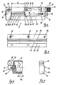
- Fig. 1 shows the basic principle of binding stacked printed products 10 on an application head 12 of an adhesive application station 14 (FIGS. 3 to 5).
- a Sliding surface 16 of a nozzle block 18 of the application head 12 is from one in Longitudinal exit slit 20 for an adhesive 52 (FIG. 2) penetrated.
- the slot width s is the exit slot 20 at about 0.2 mm. This slot width is usually not changeable, it can also be adjustable.
- the sliding surface 16 is laterally from a fixed stop 22 with a first guide surface 24, including a guide 24a, and a hold-down device 26 with a second guide surface 28, including a guide 28a for a printed product 10, limited
- the hold-down 26 is in the direction of Double arrow 30, which runs parallel to the outlet slot 20, and exactly positionable.
- the hold-down 26 guides a slide 32, which within a narrow tolerance range t in the direction of the also parallel to the outlet slot 20 extending double arrow 34 against a resilient force can be pressed into the hold-down device 26.
- the slide 32 has a third guide surface 36 for stacked printed products 10, likewise with a guide 36a.
- Both this third guide surface 36 and the first guide surface 24 are angled and widen as a guide 24a, 36a against the insertion direction E for stacked printed products 10 on.
- the narrow tolerance range t for the slide which can be traced by spring force 32 is through a bore 38 in the holding-down device 26 and one in this bore limited by the slider 32 projecting bolt 40.
- the hold-down device is used to bind stacked printed products 26 with the slider 32 corresponding to the minimum thickness d of the stacked Printed products 10 positioned and e.g. set with a screw. at a tolerance range of, for example, 0.5 mm for the thicknesses d of the stacked Printed products, the width g of the sliding surface 16 to the distance d + t set, provided the slide 32 is at maximum tolerance t pressed in flush with the second guide surface 28. Impression of the Slide 32 takes place when stacked printed products 10 are introduced, if this along guides 24a, 36a of the first and third guide surfaces 24, 36 can be pushed.
- the adhesive application is mechanical, electronic or sensor controlled and is terminated when the printed product 10 reaches the area of the exit slot 20 leaves.
- Both the hold-down 26 and the slide 32 seal the exit slot 20 if and where they rest on the sliding surface 16.
- the slide 32 omitted and the hold-down 26 itself as resilient in the tolerance range movable stop be formed.
- the stacked ones slide Printed products 10 along the second guide surface 28 with a guide.
- FIG. 1 The functional description of Fig. 1 is drawn by the reverse Fig. 2 added.
- a slot nozzle 42 is outlined in the application head 12, which the exit slot 20 shown in Fig. 1 and one in a bore of the application head Includes 12 guided metering shaft 44 with a diagonal slot 46. This extends over the length of the outlet slot 20.
- a pressure chamber adhesive store 50 which with a dissolved or melted adhesive 52 is filled.
- a pressure accumulator 54 a pressure cylinder 56 with a pressure stamp 58 is arranged, which can be moved in the direction of the double arrow 60 and into the adhesive store 50 protrudes.
- the printing system for the adhesive application shown in FIG. 2 is in the middle position.
- the diagonal slot 46 communicating with the adhesive is closed.
- the pressure loss that occurs due to the release of adhesive in the adhesive store 50 is automatically compensated by the pressure stamp 58 accordingly is pushed deeper into the adhesive store 50.
- the pressure in the adhesive store 50 is determined by the cross-sectional ratio of the impression cylinder 56 to the pressure stamp 58 and the pressure in an antechamber 64 of the pressure accumulator 54 determined.
- the pressure in this antechamber is in the range of, for example 0.7 to 0.8 bar.
- the binding process for the stacked printed products can 10 can also be done manually or semi-automatically.
- FIG. 3 to 5 A basic design principle of an adhesive application station 14 is shown in FIG. 3 to 5 shown.
- the functional division into application head 12, adhesive storage 50 (pressure chamber) and pressure accumulator 54 can be seen.
- the essential Individual elements of the application head 12 are shown in detail in FIGS. 6 to 15 shown.
- the application head 12 comprises a nozzle block 18 as a carrier, which as a profile trained or milled or drilled out of a solid block.
- a hold-down 26 is over the area of a much larger elongated hole 68 positionable.
- the end of the hold-down device 26 is the second lateral guide surface 28 trained.
- a front end of the nozzle block 18 is screwed to a guide block 72, which for precise positioning of the hold-down 26 by an adjusting screw 74 is reached.
- This adjusting screw 74 also includes a knurled nut 76 an adjustment scale 78, which can also be designed as a vernier.
- the hold-down 26 can also be automatically positioned using other means known per se be, for example with a linear motor, stepper motor, hydraulic or pneumatic means.
- a corresponding bore of the nozzle block 18 is one with the outlet slot 20 the slit nozzle 42 forming metering shaft 44 which via a pivotable lever 80 is manually or automatically operated by machine.
- the application head 12 is directly with a separate, designed as a pressure chamber Adhesive reservoir 50 screwed and sealed.
- a filler neck 82 for the adhesive store 50 has an external thread and can thus directly with an interchangeable, larger adhesive reservoir can be connected, for example a barrel pump. This means that the adhesive is absolutely free of air guaranteed. The prevention of the Contact of adhesive with air has been reached.
- the pressure accumulator 54 is connected to the adhesive accumulator via four spacer tubes 84 50 connected.
- a bore 86 for compressed air is indicated, which includes the usual connection fittings not shown.
- the print medium is guided into an anteroom (64 in FIG. 2) and acts on one with a broken line indicated pressure cylinder 56, which multiplies the pressure proportional to the area transfers into the adhesive store 50 via a pressure stamp 58.
- FIG. 6 shows an application head 12 in plan view, it essentially corresponds - but reversed - Fig. 3. For clarity especially the fixing screws for the fixed stop 22 and the hold-down 26, there are only the holes 88.90 for bolts in the Elongated holes 66, 68 can be seen.
- FIG. 6 shows not only the outlet slot in the longitudinal direction 20 for the adhesive, but also longitudinal guide elements.
- the sliding surface 16 is angled slightly downward along an edge 92 and thus forms an inclined insertion ramp 62 for easier insertion of the stacked printed matter.
- a hardly noticeable first gradation 94 and a larger gradation 96 also serve for easier attachment the hold-down 26, the fixed stop 22 and the guide block 72.
- the width g of the sliding surface 16 is practically at the maximum possible value set. You could add a little by moving the fixed stop 22 can be enlarged.
- the minimum width g of the sliding surface 16 is due to the Length of the elongated holes 66 and in particular 68 limited.
- a set screw 98 can be seen in the hold-down device 26. With this, the spring force of the slide 32 guided by the hold-down device 26 (FIG. 1) become.
- FIG. 7 shows a nozzle block 18 without additional elements. It corresponds essentially Fig. 6. However, it is not a first step 94 as a guide element educated. This ensures an improved sliding surface 16.
- the bore 100 with an internal thread serves to receive a fastening screw for the guide block 72.
- FIG. 8 shows hatched lines the end face of the nozzle block 18. Below the guide block 72 with the Knurled nut 76 is part of the adjustment plate 70 and at the bottom part of the Hold-down 26 visible.
- electrical cables, distributors and the like can be electrical Components are stored.
- FIGS. 10, 11 and 12. 10 shows the slider 32 projecting approximately 0.4 mm with the third lateral guide 36, which according to FIG. 1 with formation of the third guide 36a is slightly angled.
- the slide 32 can against the resistance of a coil spring 106 is pressed into the hold-down device 26 until the second guide surface 28 with the third guide surface 36 runs flush.
- the stroke restriction of the slide 32 is as already mentioned ensured by the bolt 40 in the bore 38.
- the hold-down 26 is penetrated in the longitudinal direction by a bore 108, which free space for the adjusting screw 70 creates.
- the second guide surface 28 of the hold-down device 26 is visible in FIG. 11.
- the second guide surface 28 is around an edge 110 to form a guide 26a slightly angled together with the guide 24a of the first guide surface 24 of the fixed stop 22 (FIG. 9) results in a wider insertion opening for the stacked printed products.
- the slider 32 or its third guide surface 36 is also angled to a shifted Edge 112. For better guidance in the hold-down device 26, the slide 32 a flat longitudinal groove 114 of shallow depth.
- the slide 32 has a bore 116 with an internal thread into which a spiral spring 116 and a corresponding ball 118 be pushed.
- the spring can be preloaded with a set screw 98 become.
- 13 and 14 is an adjusting screw 74 with knurled nut 76 and Classification 78 together with the associated guide block 72 with a corresponding one Hole 120 shown with internal thread.
- a shaft lock 122 is also hinted at.
- a metering shaft 44 shown in FIG. 15 has a shaft lock at one end 122 equipped and another is a swivel lever 80 for manual or mechanical application of a torque attached.
- An Allen screw 126 which with its tip in a conical recess of the Metering shaft 44 is secured prevents the lever 80 from turning empty.
- a longitudinal groove which is functional corresponds to a diagonal slot 46 (FIG. 2).
- a radial channel 124 provided, which with the dosing shaft in the working position Secures glue supply.
Landscapes
- Coating Apparatus (AREA)
- Folding Of Thin Sheet-Like Materials, Special Discharging Devices, And Others (AREA)
- Adhesives Or Adhesive Processes (AREA)
Description
- Nach einer ersten Variante kann ein geführter Schlitten als ganzes federnd auf einem Düsenblock des Auftragskopfs in Richtung des Austrittsschlitzes verschiebbar sein und mit seiner Führungsfläche einen federnden Anschlag bilden.
- Nach einer weiteren Variante kann eine in einem positionierbaren Halter in Schlitzrichtung verschiebbare, zweckmässig zylindrische Rolle mit zur Gleitfläche rechtwinkliger Achse, Führungsfläche sein.
- Nach einer Variante ist ein in Schlitzrichtung geführter Schieber mit einer entsprechend ausgebildeten stirnseitigen Führungsfläche ausgebildet. Der Schieber ist in Richtung des Führungsschlitzes, beispielsweise gegen den Widerstand einer Feder oder gegen einen pneumatischen Druck, verschiebbar und in einem exakt positionierbaren Niederhalter angeordnet.
- Nach einer letzten hier erwähnten Variante ist eine Blattfeder auf einem bereits erwähnten positionierbaren Halter stirnseitig so angeordnet, dass sie eine in Schlitzrichtung um etwa ± 1 mm elastisch verformbare Führungsfläche bildet. Es sind verschiedene Arten von Blattfedern geeignet, welche gleichzeitig im Toleranzbereich von etwa ± 1 mm den Austrittsschlitz abdecken.
- Fig. 1 eine Prinzipskizze des Bindebereichs eines Auftragskopfs eines Kleberauftragssystems in Draufsicht,
- Fig. 2 eine Prinzipskizze eines Drucksystems mit Druckausgleich im Schnitt,
- Fig. 3 eine Draufsicht auf eine Kleberauftragsstation,
- Fig. 4 eine Ansicht von Fig. 3,
- Fig. 5 eine Seitenansicht von Fig. 3 (von links),
- Fig. 6 einen Auftragskopf in Draufsicht,
- Fig. 7 einen Düsenblock von Fig. 6,
- Fig. 8 eine Seitenansicht von Fig. 6 (von rechts),
- Fig. 9 einen Fixanschlag,
- Fig. 10 einen Niederhalter in Draufsicht,
- Fig. 11 eine Seitenansicht von Fig. 10 (von links),
- Fig. 12 eine Schieberplatte in Draufsicht, auseinander gezogen,
- Fig. 13 eine Einstellschraube für einen Niederhalter,
- Fig. 14 einen Führungsblock für die Einstellschraube, und
- Fig. 15 eine Dosierwelle.
Claims (10)
- Kleberauftragsstation (14) zum Binden von gestapelten Druckerzeugnissen (10) mittels eines fliessfähigen oder verflüssigbaren Klebstoffes (52), welche Auftragsstation (14)umfasst,einen Auftragskopf (12) für den Klebstoff (52) mit einer Gleitfläche (16) für die Druckerzeugnisse (10), beidseits dieser Gleitfläche (16) je einem Anschlag (22,26) für diese Druckerzeugnisse (10) und einer sich über die ganze Breite (g) der Gleitfläche (16) erstreckenden Schlitzdüse (42) für den Klebstoff (52),einen als Druckkammer ausgebildeten Klebstoffspeicher (50) undMittel zur Erzeugung eines Druckes im Klebstoffspeicher (50)
dadurch gekennzeichnet, dass
wenigstens ein seitlicher Anschlag (22,26,32) als innerhalb eines engen Toleranzbereiches (t) unterschiedliche Dicken (d) der durchlaufenden gestapelten Druckerzeugnisse (10) automatisch ausgleichende seitliche Führungsfläche (24, 24a, 28,28a oder 36,36a) ausgebildet ist, und ein in diesem Toleranzbereich (t) rückführbar bewegbarer Anschlag (26 oder 32) stets dichtend auf einem Austrittsschlitz(20) der Schlitzdüse (42) für den Klebstoff (52) in der Gleitfläche (16) aufliegt. - Kleberauftragsstation (14) nach Anspruch 1, dadurch gekennzeichnet, dass der Toleranzbereich (t) bis etwa ± 1 mm beträgt, vorzugsweise bis etwa ± 0,5 mm.
- Kieberauftragsstation (14) nach Anspruch 1 oder 2, dadurch gekennzeichnet, dass ein Fixanschlag (22) und ein innerhalb des Toleranzbereichs (t) federnder Anschlag (26 oder 32) ausgebildet ist, vorzugsweise mit sich in Einführungsrichtung (E) der Druckerzeugnisse (10) als Einweiser (24a,28a,36a) verengenden seitlichen Führungsflächen (24,28,36).
- Kleberauftragsstation (14) nach einem der Ansprüche 1 bis 3, dadurch gekennzeichnet, dass der in Schlitzrichtung federnde Anschlag (26 oder 32) mit der Führungsfläche (28,28a,36,36a) ein als ganzes auf einem Düsenblock (18) mechanisch oder pneumatisch geführter Schlitten, eine in einem positionierbaren Halter geführte Rolle, ein in einem positionierbaren Niederhalter (26) geführter Schieber (32) oder eine in einem positionierbaren Halter geführte Blattfeder ist.
- Kleberauftragsstation (14) nach Anspruch 4, dadurch gekennzeichnet, dass der bewegliche Anschlag mit vorzugsweise einstellbarer Federkraft oder pneumatisch rückführbar ist.
- Kleberauftragsstation (14) nach einem der Ansprüche 1 bis 5, dadurch gekennzeichnet, dass die Breite (s) des Austrittsschlitzes (20) einstellbar ist.
- Kleberauftragsstation (14) nach einem der Ansprüche 1 bis 6, dadurch gekennzeichnet, dass die Schlitzdüse (42) eine unmittelbar unterhalb des Austrittsschlitzes (20) manuell oder gesteuert maschinell drehbare Dosierwelle (44) mit einem längslaufenden Schlitz (46) umfasst, welcher sich über die ganze Länge des Austrittsschlitzes (20) erstreckt und in Arbeitsposition der Dosierwelle (44) den Austrittsschlitz (20) mit dem direkt anschliessenden Klebstoffspeicher (50) kommunizierend verbindet.
- Kleberauftragsstation (14) nach Anspruch 7, dadurch gekennzeichnet, dass ein integrierter Druckspeicher (54) mit direkt auf den im oder unterhalb des Auftragskopfs (12) angeordneten Klebstoffspeicher (50) einwirkenden Mitteln ausgebildet ist und so nach jeder Klebstoffabgabe eine automatische Druckkompensation gewährleistet.
- Kleberauftragsstation (14) nach Anspruch 8, dadurch gekennzeichnet, dass ein Druckzylinder (56) mittels des Druckspeichers (54) über einen Druckstempel (58) direkt auf den Klebstoff (52) im Klebstoffspeicher (50) einwirkt.
- Kleberauftragsstation (14) nach einem der Ansprüche 1 bis 9, dadurch gekennzeichnet, dass im Auftragskopf (12) und/oder im Klebstoffspeicher (50) wenigstens eine sensorgesteuerte Heizpatrone (102) angeordnet ist.
Priority Applications (1)
| Application Number | Priority Date | Filing Date | Title |
|---|---|---|---|
| EP00904782A EP1156931B1 (de) | 1999-03-01 | 2000-02-25 | Kleberauftragsstation für druckerzeugnisse |
Applications Claiming Priority (4)
| Application Number | Priority Date | Filing Date | Title |
|---|---|---|---|
| EP99810173 | 1999-03-01 | ||
| EP99810173A EP1033262A1 (de) | 1999-03-01 | 1999-03-01 | Kleberauftragsstation für Druckerzeugnisse |
| PCT/CH2000/000105 WO2000051826A1 (de) | 1999-03-01 | 2000-02-25 | Kleberauftragsstation für druckerzeugnisse |
| EP00904782A EP1156931B1 (de) | 1999-03-01 | 2000-02-25 | Kleberauftragsstation für druckerzeugnisse |
Publications (2)
| Publication Number | Publication Date |
|---|---|
| EP1156931A1 EP1156931A1 (de) | 2001-11-28 |
| EP1156931B1 true EP1156931B1 (de) | 2003-01-15 |
Family
ID=8242701
Family Applications (2)
| Application Number | Title | Priority Date | Filing Date |
|---|---|---|---|
| EP99810173A Withdrawn EP1033262A1 (de) | 1999-03-01 | 1999-03-01 | Kleberauftragsstation für Druckerzeugnisse |
| EP00904782A Expired - Lifetime EP1156931B1 (de) | 1999-03-01 | 2000-02-25 | Kleberauftragsstation für druckerzeugnisse |
Family Applications Before (1)
| Application Number | Title | Priority Date | Filing Date |
|---|---|---|---|
| EP99810173A Withdrawn EP1033262A1 (de) | 1999-03-01 | 1999-03-01 | Kleberauftragsstation für Druckerzeugnisse |
Country Status (6)
| Country | Link |
|---|---|
| US (1) | US6695031B1 (de) |
| EP (2) | EP1033262A1 (de) |
| AT (1) | ATE231076T1 (de) |
| AU (1) | AU2655600A (de) |
| DE (1) | DE50001097D1 (de) |
| WO (1) | WO2000051826A1 (de) |
Cited By (1)
| Publication number | Priority date | Publication date | Assignee | Title |
|---|---|---|---|---|
| EP1743777A1 (de) | 2005-07-15 | 2007-01-17 | Balti AG | Kleberauftragstation |
Families Citing this family (8)
| Publication number | Priority date | Publication date | Assignee | Title |
|---|---|---|---|---|
| DE20216794U1 (de) * | 2002-10-30 | 2004-03-11 | Nordson Corporation, Westlake | Vorrichtung zum Auftragen von Fluid |
| US7507295B2 (en) * | 2005-03-22 | 2009-03-24 | Nordson Corporation | Adhesive dispenser |
| DE102005044273A1 (de) * | 2005-09-16 | 2007-03-29 | Heidelberger Druckmaschinen Ag | Düsenauftragssystem für Klebstoff |
| US8127711B2 (en) * | 2007-07-05 | 2012-03-06 | Nordson Corporation | Mounting systems for an adhesive application system and methods for applying adhesive |
| DE202012008417U1 (de) * | 2012-07-10 | 2012-09-27 | Heidelberger Druckmaschinen Ag | Vorrichtung zum Auftragen von Klebstoff |
| EP2832556B1 (de) * | 2013-08-02 | 2016-11-09 | Maping Kommandiittiyhtiö L. Huotari | System zur Verwendung einer auswechselbaren Leimpatrone, und eine Buchbindemaschine |
| US10363567B2 (en) * | 2016-02-29 | 2019-07-30 | The Boeing Company | Apparatuses for applying a glutinous substance |
| EP3569320A1 (de) * | 2018-05-15 | 2019-11-20 | Ribler GmbH | Vorrichtung und verfahren zum auftragen von klebstoff auf druckereierzeugnisse |
Family Cites Families (4)
| Publication number | Priority date | Publication date | Assignee | Title |
|---|---|---|---|---|
| IT1161930B (it) * | 1983-05-19 | 1987-03-18 | Plastiver Di Giovanni Vigano & | Dispositivo e procedimento per spalmare liquidi,in particolare colla su dorsi di libri |
| US5271794A (en) * | 1992-01-09 | 1993-12-21 | Nordson Corporation | Adjustable width coating nozzle and side sealer |
| US5418009A (en) * | 1992-07-08 | 1995-05-23 | Nordson Corporation | Apparatus and methods for intermittently applying discrete adhesive coatings |
| DE19756958A1 (de) * | 1997-12-20 | 1999-07-15 | Womako Masch Konstr | Vorrichtung zum Beleimen von Blockrücken |
-
1999
- 1999-03-01 EP EP99810173A patent/EP1033262A1/de not_active Withdrawn
-
2000
- 2000-02-25 US US09/913,662 patent/US6695031B1/en not_active Expired - Fee Related
- 2000-02-25 EP EP00904782A patent/EP1156931B1/de not_active Expired - Lifetime
- 2000-02-25 DE DE50001097T patent/DE50001097D1/de not_active Expired - Fee Related
- 2000-02-25 WO PCT/CH2000/000105 patent/WO2000051826A1/de not_active Ceased
- 2000-02-25 AT AT00904782T patent/ATE231076T1/de not_active IP Right Cessation
- 2000-02-25 AU AU26556/00A patent/AU2655600A/en not_active Abandoned
Cited By (1)
| Publication number | Priority date | Publication date | Assignee | Title |
|---|---|---|---|---|
| EP1743777A1 (de) | 2005-07-15 | 2007-01-17 | Balti AG | Kleberauftragstation |
Also Published As
| Publication number | Publication date |
|---|---|
| EP1033262A1 (de) | 2000-09-06 |
| AU2655600A (en) | 2000-09-21 |
| ATE231076T1 (de) | 2003-02-15 |
| US6695031B1 (en) | 2004-02-24 |
| WO2000051826A1 (de) | 2000-09-08 |
| EP1156931A1 (de) | 2001-11-28 |
| DE50001097D1 (de) | 2003-02-20 |
Similar Documents
| Publication | Publication Date | Title |
|---|---|---|
| AT517318B1 (de) | Stempel und Abdruckeinheit | |
| DE4012825C2 (de) | ||
| DE10320813B4 (de) | Vorrichtung zum flächigen Auftragen von viskosen Medien | |
| EP1156931B1 (de) | Kleberauftragsstation für druckerzeugnisse | |
| DE2951651C2 (de) | Vorrichtung zum dosierten Aufbringen von Farbe mittels von Pumpen versorgter Farbdüsen auf die Farbauftragwalzen eines Farbwerks | |
| DE19617167C2 (de) | Drucker mit Führungswellenanordnung | |
| EP1172230A2 (de) | Kleberauftragsstation für Druckerzeugnisse | |
| DE2425140B2 (de) | Vorrichtung zum Zuführen von Etiketten, Anhängern u.dgl | |
| DE3014823C2 (de) | Matrixdrucker mit einem zur Druckspalteinstellung anstellbaren Druckkopf | |
| DE3902859C2 (de) | ||
| DE3417381A1 (de) | Vorrichtung zur automatischen papierdickenanpassung eines druckerkopfes | |
| EP2204284B1 (de) | Farbkastentrennung | |
| EP3546070A1 (de) | Vorrichtung zum auftragen eines fliessfähigen stoffs auf ein substrat | |
| EP1866167A1 (de) | Kleberauftragsstation zum binden von druckerzeugnissen | |
| DE8005406U1 (de) | Geraet zum auftragen eines farbstreifenmusters | |
| DE10338224B4 (de) | Farbdosiereinrichtung mit beweglicher Schieberspitze | |
| DE202007007036U1 (de) | Mikrobreitenverstellbare Schlitzdüse | |
| DE2913980C2 (de) | ||
| EP1093894A2 (de) | Schneidvorrichtung | |
| DE1800261C (de) | Mehrteiliges Druckwiderlager zum gleichmaßigen und in einer Ebene ausgerich teten Einspannen von Formularen fur Nadel druckwerke von Buchungs und Fakturier maschinen | |
| DE3026666A1 (de) | Farbdosiereinrichtung fuer druckmaschine | |
| DE2603396A1 (de) | Buchbindeverfahren und -vorrichtung | |
| DE3324700A1 (de) | Beschichtungsvorrichtung | |
| DE202016100365U1 (de) | Pastenführungselement für Rakelhalter und Rakelhalter mit Pastenführungselement | |
| DE2118570C2 (de) | Handvorrichtung zum Aufbringen einer selbstklebenden Kunststoffolle auf eine Oberfläche einer Gardinenleiste |
Legal Events
| Date | Code | Title | Description |
|---|---|---|---|
| PUAI | Public reference made under article 153(3) epc to a published international application that has entered the european phase |
Free format text: ORIGINAL CODE: 0009012 |
|
| 17P | Request for examination filed |
Effective date: 20010816 |
|
| AK | Designated contracting states |
Kind code of ref document: A1 Designated state(s): AT BE CH CY DE DK ES FI FR GB GR IE IT LI LU MC NL PT SE |
|
| AX | Request for extension of the european patent |
Free format text: AL;LT;LV;MK;RO;SI |
|
| GRAH | Despatch of communication of intention to grant a patent |
Free format text: ORIGINAL CODE: EPIDOS IGRA |
|
| GRAH | Despatch of communication of intention to grant a patent |
Free format text: ORIGINAL CODE: EPIDOS IGRA |
|
| GRAA | (expected) grant |
Free format text: ORIGINAL CODE: 0009210 |
|
| AK | Designated contracting states |
Kind code of ref document: B1 Designated state(s): AT BE CH CY DE DK ES FI FR GB GR IE IT LI LU MC NL PT SE |
|
| PG25 | Lapsed in a contracting state [announced via postgrant information from national office to epo] |
Ref country code: GR Free format text: LAPSE BECAUSE OF FAILURE TO SUBMIT A TRANSLATION OF THE DESCRIPTION OR TO PAY THE FEE WITHIN THE PRESCRIBED TIME-LIMIT Effective date: 20030115 Ref country code: IE Free format text: LAPSE BECAUSE OF FAILURE TO SUBMIT A TRANSLATION OF THE DESCRIPTION OR TO PAY THE FEE WITHIN THE PRESCRIBED TIME-LIMIT Effective date: 20030115 Ref country code: FI Free format text: LAPSE BECAUSE OF FAILURE TO SUBMIT A TRANSLATION OF THE DESCRIPTION OR TO PAY THE FEE WITHIN THE PRESCRIBED TIME-LIMIT Effective date: 20030115 Ref country code: NL Free format text: LAPSE BECAUSE OF FAILURE TO SUBMIT A TRANSLATION OF THE DESCRIPTION OR TO PAY THE FEE WITHIN THE PRESCRIBED TIME-LIMIT Effective date: 20030115 |
|
| REG | Reference to a national code |
Ref country code: CH Ref legal event code: EP Ref country code: GB Ref legal event code: FG4D Free format text: NOT ENGLISH |
|
| REG | Reference to a national code |
Ref country code: IE Ref legal event code: FG4D Free format text: GERMAN |
|
| REF | Corresponds to: |
Ref document number: 50001097 Country of ref document: DE Date of ref document: 20030220 Kind code of ref document: P |
|
| PG25 | Lapsed in a contracting state [announced via postgrant information from national office to epo] |
Ref country code: CY Free format text: LAPSE BECAUSE OF FAILURE TO SUBMIT A TRANSLATION OF THE DESCRIPTION OR TO PAY THE FEE WITHIN THE PRESCRIBED TIME-LIMIT Effective date: 20030225 Ref country code: LU Free format text: LAPSE BECAUSE OF NON-PAYMENT OF DUE FEES Effective date: 20030225 |
|
| PG25 | Lapsed in a contracting state [announced via postgrant information from national office to epo] |
Ref country code: MC Free format text: LAPSE BECAUSE OF NON-PAYMENT OF DUE FEES Effective date: 20030228 Ref country code: BE Free format text: LAPSE BECAUSE OF NON-PAYMENT OF DUE FEES Effective date: 20030228 |
|
| PG25 | Lapsed in a contracting state [announced via postgrant information from national office to epo] |
Ref country code: DK Free format text: LAPSE BECAUSE OF FAILURE TO SUBMIT A TRANSLATION OF THE DESCRIPTION OR TO PAY THE FEE WITHIN THE PRESCRIBED TIME-LIMIT Effective date: 20030415 Ref country code: SE Free format text: LAPSE BECAUSE OF FAILURE TO SUBMIT A TRANSLATION OF THE DESCRIPTION OR TO PAY THE FEE WITHIN THE PRESCRIBED TIME-LIMIT Effective date: 20030415 Ref country code: PT Free format text: LAPSE BECAUSE OF FAILURE TO SUBMIT A TRANSLATION OF THE DESCRIPTION OR TO PAY THE FEE WITHIN THE PRESCRIBED TIME-LIMIT Effective date: 20030415 |
|
| REG | Reference to a national code |
Ref country code: CH Ref legal event code: NV Representative=s name: PETER RUTZ |
|
| GBT | Gb: translation of ep patent filed (gb section 77(6)(a)/1977) |
Effective date: 20030515 |
|
| LTIE | Lt: invalidation of european patent or patent extension |
Effective date: 20030115 |
|
| NLV1 | Nl: lapsed or annulled due to failure to fulfill the requirements of art. 29p and 29m of the patents act | ||
| PG25 | Lapsed in a contracting state [announced via postgrant information from national office to epo] |
Ref country code: ES Free format text: LAPSE BECAUSE OF FAILURE TO SUBMIT A TRANSLATION OF THE DESCRIPTION OR TO PAY THE FEE WITHIN THE PRESCRIBED TIME-LIMIT Effective date: 20030730 |
|
| REG | Reference to a national code |
Ref country code: IE Ref legal event code: FD4D Ref document number: 1156931E Country of ref document: IE |
|
| ET | Fr: translation filed | ||
| PLBE | No opposition filed within time limit |
Free format text: ORIGINAL CODE: 0009261 |
|
| STAA | Information on the status of an ep patent application or granted ep patent |
Free format text: STATUS: NO OPPOSITION FILED WITHIN TIME LIMIT |
|
| 26N | No opposition filed |
Effective date: 20031016 |
|
| PGFP | Annual fee paid to national office [announced via postgrant information from national office to epo] |
Ref country code: CH Payment date: 20080110 Year of fee payment: 9 |
|
| PGFP | Annual fee paid to national office [announced via postgrant information from national office to epo] |
Ref country code: DE Payment date: 20080219 Year of fee payment: 9 Ref country code: GB Payment date: 20080220 Year of fee payment: 9 Ref country code: IT Payment date: 20080223 Year of fee payment: 9 |
|
| PGFP | Annual fee paid to national office [announced via postgrant information from national office to epo] |
Ref country code: AT Payment date: 20080215 Year of fee payment: 9 |
|
| PGFP | Annual fee paid to national office [announced via postgrant information from national office to epo] |
Ref country code: FR Payment date: 20080214 Year of fee payment: 9 |
|
| REG | Reference to a national code |
Ref country code: CH Ref legal event code: PL |
|
| GBPC | Gb: european patent ceased through non-payment of renewal fee |
Effective date: 20090225 |
|
| PG25 | Lapsed in a contracting state [announced via postgrant information from national office to epo] |
Ref country code: CH Free format text: LAPSE BECAUSE OF NON-PAYMENT OF DUE FEES Effective date: 20090228 Ref country code: LI Free format text: LAPSE BECAUSE OF NON-PAYMENT OF DUE FEES Effective date: 20090228 Ref country code: AT Free format text: LAPSE BECAUSE OF NON-PAYMENT OF DUE FEES Effective date: 20090225 |
|
| REG | Reference to a national code |
Ref country code: FR Ref legal event code: ST Effective date: 20091030 |
|
| PG25 | Lapsed in a contracting state [announced via postgrant information from national office to epo] |
Ref country code: DE Free format text: LAPSE BECAUSE OF NON-PAYMENT OF DUE FEES Effective date: 20090901 |
|
| PG25 | Lapsed in a contracting state [announced via postgrant information from national office to epo] |
Ref country code: GB Free format text: LAPSE BECAUSE OF NON-PAYMENT OF DUE FEES Effective date: 20090225 Ref country code: FR Free format text: LAPSE BECAUSE OF NON-PAYMENT OF DUE FEES Effective date: 20090302 |
|
| PG25 | Lapsed in a contracting state [announced via postgrant information from national office to epo] |
Ref country code: IT Free format text: LAPSE BECAUSE OF NON-PAYMENT OF DUE FEES Effective date: 20090225 |