EP1157748A1 - Glue tool and use thereof - Google Patents
Glue tool and use thereof Download PDFInfo
- Publication number
- EP1157748A1 EP1157748A1 EP01112545A EP01112545A EP1157748A1 EP 1157748 A1 EP1157748 A1 EP 1157748A1 EP 01112545 A EP01112545 A EP 01112545A EP 01112545 A EP01112545 A EP 01112545A EP 1157748 A1 EP1157748 A1 EP 1157748A1
- Authority
- EP
- European Patent Office
- Prior art keywords
- glueing
- outlet
- tool according
- glue
- chamber
- Prior art date
- Legal status (The legal status is an assumption and is not a legal conclusion. Google has not performed a legal analysis and makes no representation as to the accuracy of the status listed.)
- Withdrawn
Links
- 239000003292 glue Substances 0.000 title claims abstract description 43
- 238000004026 adhesive bonding Methods 0.000 claims abstract description 42
- 230000003213 activating effect Effects 0.000 claims description 7
- 238000007599 discharging Methods 0.000 claims description 3
- 230000007704 transition Effects 0.000 claims description 3
- 229910000831 Steel Inorganic materials 0.000 claims description 2
- 239000004033 plastic Substances 0.000 claims description 2
- 229910001220 stainless steel Inorganic materials 0.000 claims description 2
- 239000010935 stainless steel Substances 0.000 claims description 2
- 239000010959 steel Substances 0.000 claims description 2
- 238000004140 cleaning Methods 0.000 description 2
- 239000000463 material Substances 0.000 description 2
- 238000000926 separation method Methods 0.000 description 1
- 239000002904 solvent Substances 0.000 description 1
- XLYOFNOQVPJJNP-UHFFFAOYSA-N water Substances O XLYOFNOQVPJJNP-UHFFFAOYSA-N 0.000 description 1
Images


Classifications
-
- B—PERFORMING OPERATIONS; TRANSPORTING
- B05—SPRAYING OR ATOMISING IN GENERAL; APPLYING FLUENT MATERIALS TO SURFACES, IN GENERAL
- B05C—APPARATUS FOR APPLYING FLUENT MATERIALS TO SURFACES, IN GENERAL
- B05C17/00—Hand tools or apparatus using hand held tools, for applying liquids or other fluent materials to, for spreading applied liquids or other fluent materials on, or for partially removing applied liquids or other fluent materials from, surfaces
- B05C17/005—Hand tools or apparatus using hand held tools, for applying liquids or other fluent materials to, for spreading applied liquids or other fluent materials on, or for partially removing applied liquids or other fluent materials from, surfaces for discharging material from a reservoir or container located in or on the hand tool through an outlet orifice by pressure without using surface contacting members like pads or brushes
- B05C17/00503—Details of the outlet element
- B05C17/00516—Shape or geometry of the outlet orifice or the outlet element
-
- B—PERFORMING OPERATIONS; TRANSPORTING
- B05—SPRAYING OR ATOMISING IN GENERAL; APPLYING FLUENT MATERIALS TO SURFACES, IN GENERAL
- B05C—APPARATUS FOR APPLYING FLUENT MATERIALS TO SURFACES, IN GENERAL
- B05C17/00—Hand tools or apparatus using hand held tools, for applying liquids or other fluent materials to, for spreading applied liquids or other fluent materials on, or for partially removing applied liquids or other fluent materials from, surfaces
- B05C17/002—Hand tools or apparatus using hand held tools, for applying liquids or other fluent materials to, for spreading applied liquids or other fluent materials on, or for partially removing applied liquids or other fluent materials from, surfaces with feed system for supplying material from an external source; Supply controls therefor
Definitions
- the present invention concerns a glueing tool for forming glue joints on large items and comprising a supply hose to a central unit for supplying glue under pressure, a handle with an activating valve, a pipe connected with a nozzle for discharging glue at its end opposite the activating valve.
- the nozzle discharging the glue has a tubular outlet.
- This tubular outlet is particularly designed for supplying and mixing the types of glue used.
- a glueing tool being peculiar in that the nozzle is formed with a chamber which at one side has an inlet stub for connecting with the pipe and which at the other side has a tapered, slot-shaped outlet with a narrow, elongate outlet opening.
- the inlet stub can be formed with slits in the longitudinal direction so that it is fastened on the tubular tools used today. Glue which is thus passed through the inlet stub will penetrate into a chamber. A volume of glue mass is built up in the chamber. In practice, when the glue mass leaves the chamber, it has thus appeared possible that the glue mass follows the whole width of a slot-shaped outlet. By providing the outlet with an outlet opening which is narrow and elongate with a length corresponding to the width of the desired glue joint it is possible in a simple way to apply a glue joint with the desired width.
- the thickness of the glue joint may be provided with great accuracy when the user is displacing the nozzle across the item with a speed corresponding to the outflow speed of the glue mass.
- Such a co-ordination of advancing speed relative to outflow speed is a property which does not require particular technical skill on the part of the user.
- the wall of the outlet at the side of the outlet aperture intended for contact with the item is tapered and ends with a sharp side edge.
- the glue mass is applied directly on the item without risk of air bubbles when it leaves the outlet opening.
- the chamber and the slot have the same width.
- the inlet stub is conical and provided with slits extending in longitudinal direction, by means of a clamp or similar it will be possible to fasten it to different pipes in known glueing tools.
- the nozzle according to the invention is thus advantageous by easily being adapted to existing glueing tools in order to modify these.
- glueing tools or at least the nozzle, of steel or stainless steel.
- glueing tools usually are provided with supply hoses supplying glue under pressure.
- the glue is usually a two component glue which is only mixed in the glueing tool itself. There will be a risk that glue remnants situated in the nozzle mouth piece may harden when the nozzle is not in use, for example, at the end of a working day.
- the glueing tool is made to be used several times, it is necessary to be able to clean the nozzle, for example at the end of a working day. Therefore, it will be an advantage if inside the nozzle there is fitted a buffer plate in front of the opening from the inlet stub so that when the nozzle is to be cleaned, solvent/water is flushed into the nozzle where it is hitting the buffer plate and is distributed in the chamber whereby is achieved an effective cleaning of the whole chamber.
- the buffer plate provides for the glue mass being evenly distributed out in the chamber so that holes and air in the glue mass is avoided at laying out.
- One form of the glueing tool may be, for example, with a flexible piece of pipe forming transition between inlet stub for nozzle and pipe for handle.
- the flexible piece of pipe may be welded together with the inlet stub and the pipe to the handle but may alternatively be made so that it is possible by means of clamps or similar to fasten it to the inlet stub and to other pipes in known glueing tools.
- the glueing tool according to the invention is peculiar in that the inlet stub has an internal diameter between 15 and 25 mm, preferably about 20 mm, that the chamber and the outlet have a width between 30 and 200 mm, preferably about 60 mm, and a height at the inlet stub between 35 and 60 mm, preferably about 45 mm, and a height at transition to outlet between 15 and 25 mm, preferably about 20 mm, and that the outlet opening has a height between 5 and 15 mm, preferably about 10 mm.
- a glueing tool with these dimensions has shown to be particularly useful for modifying a known glueing tool used for bonding half-shells for mill wings.
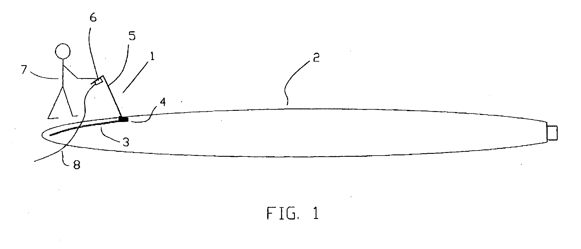
- a glueing tool 1 for use in bonding a half-shell 2 for a mill wing.
- a glue joint 3 formed by a nozzle 4.
- the nozzle 4 is provided at one end of a pipe 5 having a handle 6 at the other end, the handle 6 to be gripped by a user 7.
- the glueing tool is provided with glue mass through one or more supply hoses 8.
- Fig. 2 is seen the handle 6 with a actuating arm 9 for an activating valve 10 used for opening and closing one or more supply hoses 8.
- an activating valve 10 used for opening and closing one or more supply hoses 8.
- the nozzle 4 may be attached.
- the nozzle has an inlet stub 12 which is clamped around the tube 5 by means of a clamp 13.
- the stub may be adapted to variations in the tube diameter as slits 14 extending in the longitudinal direction of the stub are provided.
- the stub 12 is passing through a wall 15 into a chamber 16 which is communicating with a slot-shaped outlet 17.
- the chamber and the slot have the same width as the side walls 18 are provided plane.
- the outlet ends in a narrow elongate outlet opening 19.
- a bevelling see Fig. 2
- glueing tool 1 it has appeared that the chamber 16 is filled with glue mass being pressed out through the elongate outlet opening 19 with uniform thickness and speed over the whole width of the slot.
- glue joint 3 having a width corresponding to the width 22 of the slot-shaped outlet opening 19.
- Fig. 4 is seen a glueing tool with another design than shown in the previous two Figures.
- the glueing tool is made with a flexible piece of pipe 23 which at one end is fastened to the inlet stub 12 and which at the other end is fastened to a tube piece 5.
- a glueing tool shown in Fig. 4.
- the glueing tool is made with a buffer plate 24 mounted inside the chamber 16 on wall 15 and in front of the opening from inlet stub 12.
- a glueing tool according to the invention may be designed in other ways than shown on the drawing.
- the chamber may be approximately cylindrical with inlet stub and outlet situated on the cylinder surface.
Landscapes
- Engineering & Computer Science (AREA)
- Mechanical Engineering (AREA)
- Coating Apparatus (AREA)
- Physics & Mathematics (AREA)
- Geometry (AREA)
Abstract
There is disclosed a glueing tool (1) for forming glue joints (3) on large items, preferably
half-shells (2) for mill wings. In order to achieve uniform width and thickness
of the formed glue joint, the nozzle is formed by a chamber (16) which is connected
with a tapering outlet (17) ending with an elongate outlet opening (19). The outlet
opening (19) defines width and thickness on the formed glue joint.
Description
- The present invention concerns a glueing tool for forming glue joints on large items and comprising a supply hose to a central unit for supplying glue under pressure, a handle with an activating valve, a pipe connected with a nozzle for discharging glue at its end opposite the activating valve.
- By bonding large items in the shape of half-shells for mill wings, presently there is used a similar tool where the nozzle discharging the glue has a tubular outlet. This tubular outlet is particularly designed for supplying and mixing the types of glue used.
- By bonding the items together, often there is used a glue joint with a width larger than the tubular nozzle. This means that the glue is applied in a zigzag pattern. This is very demanding for the person applying the glue joint. It is important to avoid applying too little or too much glue on the items. If too little glue, there is the risk of separation later on, and if too much glue is applied, there is risk of bad hardening and excess glue being squeezed out, and for noise nuisance. Particularly by bonding tips on mill wings is very important that the glue joint is not too thick as the aerodynamic properties of the mill wing is hereby destroyed and may give rise to considerable noise.
- It is the purpose of the present invention to indicate a glueing tool of the kind mentioned in the introduction, which is relatively easy to use, even for an inexperienced user, and which at the same time enables achieving a uniform glue joint.
- According to the present invention, this is achieved with a glueing tool being peculiar in that the nozzle is formed with a chamber which at one side has an inlet stub for connecting with the pipe and which at the other side has a tapered, slot-shaped outlet with a narrow, elongate outlet opening.
- With such a glueing tool, the inlet stub can be formed with slits in the longitudinal direction so that it is fastened on the tubular tools used today. Glue which is thus passed through the inlet stub will penetrate into a chamber. A volume of glue mass is built up in the chamber. In practice, when the glue mass leaves the chamber, it has thus appeared possible that the glue mass follows the whole width of a slot-shaped outlet. By providing the outlet with an outlet opening which is narrow and elongate with a length corresponding to the width of the desired glue joint it is possible in a simple way to apply a glue joint with the desired width. If a narrow outlet opening is used, the thickness of the glue joint may be provided with great accuracy when the user is displacing the nozzle across the item with a speed corresponding to the outflow speed of the glue mass. Such a co-ordination of advancing speed relative to outflow speed is a property which does not require particular technical skill on the part of the user.
- In order to attain a glue joint on the item where there is no risk of air, it is preferred that the wall of the outlet at the side of the outlet aperture intended for contact with the item is tapered and ends with a sharp side edge. Hereby the glue mass is applied directly on the item without risk of air bubbles when it leaves the outlet opening.
- In an advantageous embodiment it is preferred that the chamber and the slot have the same width. Alternatively, it is possible to make chamber an slot with different width and thus possible to make the outlet so that it has increasing width in direction against the outlet opening.
- If the inlet stub is conical and provided with slits extending in longitudinal direction, by means of a clamp or similar it will be possible to fasten it to different pipes in known glueing tools. The nozzle according to the invention is thus advantageous by easily being adapted to existing glueing tools in order to modify these.
- It is preferred to make glueing tools, or at least the nozzle, of steel or stainless steel. Alternatively, it is possible to make it from other materials, for example plastic materials. As cleaning of the nozzle after use will be difficult, it is suitable to make it as a dispensable. Therefore it is suitable that at least the nozzle may relatively easily be made from the remaining part of the tool. In that connection it is noted that glueing tools usually are provided with supply hoses supplying glue under pressure. The glue is usually a two component glue which is only mixed in the glueing tool itself. There will be a risk that glue remnants situated in the nozzle mouth piece may harden when the nozzle is not in use, for example, at the end of a working day.
- If the glueing tool is made to be used several times, it is necessary to be able to clean the nozzle, for example at the end of a working day. Therefore, it will be an advantage if inside the nozzle there is fitted a buffer plate in front of the opening from the inlet stub so that when the nozzle is to be cleaned, solvent/water is flushed into the nozzle where it is hitting the buffer plate and is distributed in the chamber whereby is achieved an effective cleaning of the whole chamber. Besides, the buffer plate provides for the glue mass being evenly distributed out in the chamber so that holes and air in the glue mass is avoided at laying out.
- In order to achieve an even laying out of the glue mass, it is an advantage if in the glueing tool there is built in a variation dampening function for absorbing the different small irregularities and working positions. One form of the glueing tool may be, for example, with a flexible piece of pipe forming transition between inlet stub for nozzle and pipe for handle. The flexible piece of pipe may be welded together with the inlet stub and the pipe to the handle but may alternatively be made so that it is possible by means of clamps or similar to fasten it to the inlet stub and to other pipes in known glueing tools.
- In a particular embodiment, the glueing tool according to the invention is peculiar in that the inlet stub has an internal diameter between 15 and 25 mm, preferably about 20 mm, that the chamber and the outlet have a width between 30 and 200 mm, preferably about 60 mm, and a height at the inlet stub between 35 and 60 mm, preferably about 45 mm, and a height at transition to outlet between 15 and 25 mm, preferably about 20 mm, and that the outlet opening has a height between 5 and 15 mm, preferably about 10 mm. A glueing tool with these dimensions has shown to be particularly useful for modifying a known glueing tool used for bonding half-shells for mill wings.
- The invention will now be explained in more closely with reference to the accompanying schematic drawing, where:
- Fig. 1
- shows a use of a glueing tool according to the invention,
- Fig. 2
- is a partial side view of a glueing tool according to the invention,
- Fig. 3
- is a perspective view for illustrating a nozzle in a glueing tool according to the invention,
- Fig. 4
- is a side view of a glueing tool of another design,
- Fig. 5
- is a section of Fig. 4 for illustrating a buffer plate in a glueing tool, and
- Fig. 6
- is a cross-section A-A in Fig. 5 for illustrating a buffer plate in glueing tool.
- In Fig. 1 is seen a glueing
tool 1 for use in bonding a half-shell 2 for a mill wing. There is laid out aglue joint 3 formed by anozzle 4. Thenozzle 4 is provided at one end of apipe 5 having ahandle 6 at the other end, thehandle 6 to be gripped by a user 7. The glueing tool is provided with glue mass through one ormore supply hoses 8. - In Fig. 2 is seen the
handle 6 with a actuatingarm 9 for an activatingvalve 10 used for opening and closing one ormore supply hoses 8. In the shown embodiment, there is provided two supply hoses so that the two component glue mass is mixed when it is conducted throughtubes 5 from the activatingvalve 10. At the theoutlet end 11 of the tube, thenozzle 4 may be attached. As more clearly appearing from Fig. 3, the nozzle has aninlet stub 12 which is clamped around thetube 5 by means of aclamp 13. The stub may be adapted to variations in the tube diameter asslits 14 extending in the longitudinal direction of the stub are provided. Thestub 12 is passing through awall 15 into achamber 16 which is communicating with a slot-shaped outlet 17. In the embodiment shown, the chamber and the slot have the same width as theside walls 18 are provided plane. The outlet ends in a narrow elongate outlet opening 19. At the underside which is intended for contacting an item, there is provided a bevelling (see Fig. 2) so that asharp edge 21 occurs at the downward facing side of the outlet opening 19. When glueingtool 1 is used, it has appeared that thechamber 16 is filled with glue mass being pressed out through the elongate outlet opening 19 with uniform thickness and speed over the whole width of the slot. Thus it is possible to form a veryuniform glue joint 3 having a width corresponding to thewidth 22 of the slot-shapedoutlet opening 19. - In Fig. 4 is seen a glueing tool with another design than shown in the previous two Figures. The glueing tool is made with a flexible piece of
pipe 23 which at one end is fastened to theinlet stub 12 and which at the other end is fastened to atube piece 5. - In Figs. 5 and 6 is seen a glueing tool shown in Fig. 4. The glueing tool is made with a
buffer plate 24 mounted inside thechamber 16 onwall 15 and in front of the opening frominlet stub 12. - A glueing tool according to the invention may be designed in other ways than shown on the drawing. Thus it is possible to make the
outlet 17 with increasing width in direction against theoutlet opening 19. Alternatively, it is possible to design the product with different width between thechamber 16 and theoutlet 17. It is also possible to design the chamber with other shapes. For example, thechamber 16 may be approximately cylindrical with inlet stub and outlet situated on the cylinder surface.
Claims (10)
- A glueing tool for forming glue joints on large items and comprising a supply hose to a central unit for supplying glue under pressure, a handle with an activating valve, a pipe connected with a nozzle for discharging glue at its end opposite the activating valve, characterised in that the nozzle is formed with a chamber which at one side has an inlet stub for connecting with the pipe and which at the other side has a tapered, slot-shaped outlet with a narrow, elongate outlet opening.
- A glueing tool according to claim 1, characterised in that the wall of the outlet at the side of the outlet aperture intended for contact with the item is tapered and ends with a sharp side edge.
- A glueing tool according to claim 2 or 3, characterised in that the chamber and the slot have the same width.
- A glueing tool according to any preceding claim, characterised in that the inlet stub has an internal diameter between 15 and 25 mm, preferably about 20 mm, that the chamber and the outlet have a width between 30 and 200 mm, preferably about 60 mm, and a height at the inlet stub between 35 and 60 mm, preferably about 45 mm, and a height at transition to outlet between 15 and 25 mm, preferably about 20 mm, and that the outlet opening has a height between 5 and 15 mm, preferably about 10 mm.
- A glueing tool according to any preceding claim, characterised in that the inlet stub is conical and is provided with slits extending in the longitudinal direction of the stub.
- A glueing tool according to any preceding claim, characterised in that it is made of stainless steel, steel or plastic.
- A glueing tool according to any preceding claim, characterised in that the outlet has increasing width in direction toward the outlet opening.
- A glueing tool according to any preceding claim, characterised in that inside the chamber is fitted a buffer plate in front of the opening from the inlet stub.
- A glueing tool according to any preceding claim, characterised in that between the inlet stub and pipe for the activating valve there is fitted a flexible piece of pipe.
- Use of a glueing tool according to any preceding claim for glueing together half-shells for mill wings.
Applications Claiming Priority (2)
| Application Number | Priority Date | Filing Date | Title |
|---|---|---|---|
| DK200000831 | 2000-05-24 | ||
| DKPA200000831 | 2000-05-24 |
Publications (1)
| Publication Number | Publication Date |
|---|---|
| EP1157748A1 true EP1157748A1 (en) | 2001-11-28 |
Family
ID=8159514
Family Applications (1)
| Application Number | Title | Priority Date | Filing Date |
|---|---|---|---|
| EP01112545A Withdrawn EP1157748A1 (en) | 2000-05-24 | 2001-05-23 | Glue tool and use thereof |
Country Status (1)
| Country | Link |
|---|---|
| EP (1) | EP1157748A1 (en) |
Cited By (1)
| Publication number | Priority date | Publication date | Assignee | Title |
|---|---|---|---|---|
| US7325995B2 (en) | 2003-12-12 | 2008-02-05 | Medmix Systems Ag | Applicator for a dispensing appliance |
Citations (4)
| Publication number | Priority date | Publication date | Assignee | Title |
|---|---|---|---|---|
| US1829479A (en) * | 1929-06-14 | 1931-10-27 | Harry H Elkins | Plastering machine |
| FR2405757A1 (en) * | 1977-10-12 | 1979-05-11 | Lebret Sedel Sa Des Ets | Wall surface plastics coating applicator - has pump which forces material through flat nozzle to issue as sheet onto spreading roller |
| US4981384A (en) * | 1984-09-27 | 1991-01-01 | Taiyo, Ltd. | Applicator |
| US5902451A (en) * | 1996-07-15 | 1999-05-11 | Rimfire Management Corporation | Applicator for wallboard joint compound |
-
2001
- 2001-05-23 EP EP01112545A patent/EP1157748A1/en not_active Withdrawn
Patent Citations (4)
| Publication number | Priority date | Publication date | Assignee | Title |
|---|---|---|---|---|
| US1829479A (en) * | 1929-06-14 | 1931-10-27 | Harry H Elkins | Plastering machine |
| FR2405757A1 (en) * | 1977-10-12 | 1979-05-11 | Lebret Sedel Sa Des Ets | Wall surface plastics coating applicator - has pump which forces material through flat nozzle to issue as sheet onto spreading roller |
| US4981384A (en) * | 1984-09-27 | 1991-01-01 | Taiyo, Ltd. | Applicator |
| US5902451A (en) * | 1996-07-15 | 1999-05-11 | Rimfire Management Corporation | Applicator for wallboard joint compound |
Cited By (1)
| Publication number | Priority date | Publication date | Assignee | Title |
|---|---|---|---|---|
| US7325995B2 (en) | 2003-12-12 | 2008-02-05 | Medmix Systems Ag | Applicator for a dispensing appliance |
Similar Documents
| Publication | Publication Date | Title |
|---|---|---|
| US6293857B1 (en) | Blast nozzle | |
| US5865555A (en) | Caulking guide | |
| US6413002B1 (en) | Aqua broom | |
| RU2107558C1 (en) | Pneumatic dust remover | |
| US5535926A (en) | Apparatus for applying mastic to a selected surface | |
| US8069531B2 (en) | Deck cleaning tool | |
| KR20090096464A (en) | Cleaning tool handle for use with a disposable toilet brush | |
| CA2035702A1 (en) | Ultrasonically generated cavitating or interrupted jet | |
| US2882716A (en) | Applying and spreading implement for mastic cementitious material | |
| US20180228278A1 (en) | Cleaner | |
| EP1157748A1 (en) | Glue tool and use thereof | |
| FI104238B (en) | Method and apparatus for cleaning pipelines | |
| US6969015B1 (en) | Particulate sauce dispensing nozzle | |
| US5419496A (en) | Water wand apparatus | |
| US2221803A (en) | Radiator cleaning device | |
| US20020166631A1 (en) | Method and apparatus for applying low viscosity cyanoacrylate adhesive on wooden furniture | |
| US20030180086A1 (en) | Grout sealer applicator brush | |
| AU605871B2 (en) | A device at washing and rinsing apparatuses for producing a foam | |
| US1111768A (en) | Cleaning apparatus. | |
| US7297217B2 (en) | Method and apparatus for applying low viscosity cyanoacrylate adhesive on wooden furniture | |
| ATE525902T1 (en) | DEVICE AND METHOD FOR DOSING FLUIDS | |
| US1613790A (en) | Fountain mop | |
| DE202004006923U1 (en) | Suction hose adaptor for vacuum source has additional pressure hose to increase fluid flow by circumferential jets | |
| US798713A (en) | Flushing device. | |
| JP6510822B2 (en) | Pipe cleaning jig |
Legal Events
| Date | Code | Title | Description |
|---|---|---|---|
| PUAI | Public reference made under article 153(3) epc to a published international application that has entered the european phase |
Free format text: ORIGINAL CODE: 0009012 |
|
| AK | Designated contracting states |
Kind code of ref document: A1 Designated state(s): AT BE CH CY DE DK ES FI FR GB GR IE IT LI LU MC NL PT SE TR |
|
| AX | Request for extension of the european patent |
Free format text: AL;LT;LV;MK;RO;SI |
|
| AKX | Designation fees paid | ||
| REG | Reference to a national code |
Ref country code: DE Ref legal event code: 8566 |
|
| STAA | Information on the status of an ep patent application or granted ep patent |
Free format text: STATUS: THE APPLICATION IS DEEMED TO BE WITHDRAWN |
|
| 18D | Application deemed to be withdrawn |
Effective date: 20020529 |