EP1158373A1 - Mechanical timepiece with regulator actuating mechanism - Google Patents
Mechanical timepiece with regulator actuating mechanism Download PDFInfo
- Publication number
- EP1158373A1 EP1158373A1 EP00902140A EP00902140A EP1158373A1 EP 1158373 A1 EP1158373 A1 EP 1158373A1 EP 00902140 A EP00902140 A EP 00902140A EP 00902140 A EP00902140 A EP 00902140A EP 1158373 A1 EP1158373 A1 EP 1158373A1
- Authority
- EP
- European Patent Office
- Prior art keywords
- mechanical timepiece
- watch
- balance
- wheel
- error
- Prior art date
- Legal status (The legal status is an assumption and is not a legal conclusion. Google has not performed a legal analysis and makes no representation as to the accuracy of the status listed.)
- Withdrawn
Links
Images


Classifications
-
- G—PHYSICS
- G04—HOROLOGY
- G04C—ELECTROMECHANICAL CLOCKS OR WATCHES
- G04C3/00—Electromechanical clocks or watches independent of other time-pieces and in which the movement is maintained by electric means
- G04C3/04—Electromechanical clocks or watches independent of other time-pieces and in which the movement is maintained by electric means wherein movement is regulated by a balance
- G04C3/047—Electromechanical clocks or watches independent of other time-pieces and in which the movement is maintained by electric means wherein movement is regulated by a balance using other coupling means, e.g. electrostrictive, magnetostrictive
-
- G—PHYSICS
- G04—HOROLOGY
- G04C—ELECTROMECHANICAL CLOCKS OR WATCHES
- G04C11/00—Synchronisation of independently-driven clocks
-
- G—PHYSICS
- G04—HOROLOGY
- G04C—ELECTROMECHANICAL CLOCKS OR WATCHES
- G04C11/00—Synchronisation of independently-driven clocks
- G04C11/08—Synchronisation of independently-driven clocks using an electro-magnet or-motor for oscillation correction
- G04C11/085—Synchronisation of independently-driven clocks using an electro-magnet or-motor for oscillation correction using an electro-motor
- G04C11/088—Synchronisation of independently-driven clocks using an electro-magnet or-motor for oscillation correction using an electro-motor acting on the balance
-
- G—PHYSICS
- G04—HOROLOGY
- G04C—ELECTROMECHANICAL CLOCKS OR WATCHES
- G04C3/00—Electromechanical clocks or watches independent of other time-pieces and in which the movement is maintained by electric means
- G04C3/04—Electromechanical clocks or watches independent of other time-pieces and in which the movement is maintained by electric means wherein movement is regulated by a balance
-
- G—PHYSICS
- G04—HOROLOGY
- G04C—ELECTROMECHANICAL CLOCKS OR WATCHES
- G04C3/00—Electromechanical clocks or watches independent of other time-pieces and in which the movement is maintained by electric means
- G04C3/08—Electromechanical clocks or watches independent of other time-pieces and in which the movement is maintained by electric means wherein movement is regulated by a mechanical oscillator other than a pendulum or balance, e.g. by a tuning fork, e.g. electrostatically
-
- G—PHYSICS
- G04—HOROLOGY
- G04C—ELECTROMECHANICAL CLOCKS OR WATCHES
- G04C3/00—Electromechanical clocks or watches independent of other time-pieces and in which the movement is maintained by electric means
- G04C3/14—Electromechanical clocks or watches independent of other time-pieces and in which the movement is maintained by electric means incorporating a stepping motor
- G04C3/146—Electromechanical clocks or watches independent of other time-pieces and in which the movement is maintained by electric means incorporating a stepping motor incorporating two or more stepping motors or rotors
Definitions
- the present invention relates to a mechanical timepiece capable of indicating time with accuracy.
- the invention relates, more specifically, to a mechanical timepiece with regulator rotation mechanism having a mechanism capable of operating the regulator to adjust a timepiece watch error.
- the mechanical-timepiece movement 1100 (mechanical body) has a main plate 1102 constituting a base plate for the movement.
- a hand setting stem 1110 is rotatably assembled in a hand-setting-stem guide hole 1102a of the main plate 1102.
- a dial 1104 (shown by the virtual line in Fig. 15) is attached to the movement 1100.
- the side having a dial is referred to as a "back side” of the movement and the opposite side to the side having the dial as a "front side”.
- the train wheel assembled on the "front side” of the movement is referred to as a “front train wheel” and the train wheel assembled on the "back side” of the movement is as a “back train wheel”.
- the hand setting stem 1110 is determined in axial position by a switch device including a setting lever 1190, a yoke 1192, a yoke spring 1194 and a back holder 1196.
- a winding pinion 1112 is rotatably provided on a guide axis portion of the hand setting stem 1110.
- the winding pinion 1112 rotates through rotation of the clutch wheel.
- a crown wheel 1114 rotates due to rotation of the winding pinion 1112.
- a ratchet wheel 1116 rotates due to rotation of the crown wheel 1114.
- a mainspring 1122 accommodated in a barrel complete 1120 is wound up.
- a center wheel and pinion 1124 rotates due to rotation of the barrel complete 1120.
- An escape wheel and pinion 1130 rotates through rotation of a fourth wheel and pinion 1128, third wheel and pinion 1126 and center wheel and pinion 1124.
- the barrel complete 1120, center wheel and pinion 1124, third wheel and pinion 1126 and fourth wheel and pinion 1128 constitutes a front train wheel.
- An escapement/speed-control device for controlling rotation of the front train wheel includes a balance with hairspring 1140, an escape wheel and pinion 1130 and pallet fork 1142.
- the balance with hairspring 1140 includes a balance stem 1140a, a balance wheel 1140b and a stud mainspring 1140c.
- an hour pinion 1150 rotates simultaneously.
- a minute hand 1152 attached on the hour wheel 1150 indicates "minute”.
- the hour pinion 1150 is provided with a slip mechanism for the center wheel and pinion 1124.
- an hour wheel 1154 rotates through rotation of a minute wheel.
- An hour hand 1156 attached on the hour wheel 1154 indicates "hour”.
- the barrel complete 1120 is rotatably supported relative to the main plate 1102 and barrel bridge 1160.
- the center wheel and pinion 1124, the third wheel and pinion 1126, the fourth wheel and pinion 1128 and the escape wheel and pinion 1130 are rotatably supported relative to the main plate 1102 and train wheel bridge 1162.
- the pallet fork 1142 is rotatably supported relative to the main plate 1102 and pallet fork bridge 1164.
- the balance with hairspring 1140 is rotatably supported relative to the main plate 1102 and balance bridge 1166.
- the stud mainspring 1140c is a thin leaf spring in a spiral (helical) form having a plurality of turns.
- the stud mainspring 1140c at an inner end is fixed to a stud ball 1140d fixed on the balance stem 1140a, and the stud mainspring 1140c at an outer end is fixed by screwing through a stud support 1170a attached to a stud bridge 1170 fixed on the balance bridge 1166.
- a regulator 1168 is rotatably attached on the balance bridge 1166.
- a stud bridge 1168a and a stud rod 1168b are attached on the regulator 1168.
- the stud mainspring 1140c has a portion close to the outer end positioned between the stud bridge 1168a and the stud rod 1168b.
- the torque on the mainspring decreases while being rewound as the sustaining time elapses from a state the mainspring is fully wound (full winding state).
- the mainspring torque in the full winding state is about 27 g ⁇ cm, which becomes about 23 g ⁇ cm at a lapse of 20 hours from the full winding state and about 18 g ⁇ cm at a lapse of 40 hours from the full winding state.
- the decrease of mainspring torque also decreases a swing angle of the balance with hairspring.
- the swing angle of the balance with hairspring is approximately 240 to 270 degrees when the mainspring torque is 25 to 28 g ⁇ cm while the swing angle of the balance with hairspring is approximately 180 to 240 degrees when the mainspring torque is 20 to 25 g ⁇ cm.
- Fig. 18 there is shown transition of an instantaneous watch error (numeral value indicative of timepiece accuracy) against a swing angle of a balance with hairspring in the conventional representative mechanical timepiece.
- instantaneous watch error refers to "a value representative of fast or slow of a mechanical timepiece at a lapse of one day on the assumption that the mechanical timepiece is allowed to stand while maintaining a state or environment of a swing angle of a balance with hairspring upon measuring a watch error".
- the instantaneous watch error delays when the swing angle of the balance with hairspring is 240 degrees or greater or 200 degrees or smaller.
- the instantaneous watch error is about 0 to 5 seconds per day (about 0 to 5 seconds fast per day) when the swing angle of the balance with hairspring is about 200 to 240 degrees while the instantaneous watch error becomes about -20 seconds per day (about 20 seconds slow per day) when the swing angle of the balance with hairspring is about 170 degrees.
- Fig. 19 there is shown a transition of an instantaneous watch error and a lapse time upon rewinding the mainspring from a full winding state in the conventional representative mechanical timepiece.
- the "watch error" indicative of timepiece advancement per day or timepiece delay per day is shown by an extremely thin line in Fig. 19, which is obtainable by integrating over 24 hours an instantaneous watch error against a lapse time of rewinding the mainspring from the full winding.
- the instantaneous watch error slows down because the mainspring torque decreases and the balance-with-hairspring swing angle decreases as the sustaining time elapses with the mainspring being rewound from a full winding state. Due to this, in the conventional mechanical timepiece, the instantaneous watch error in a mainspring full winding state is previously put forward in expectation of timepiece delay after lapse of a sustaining time of 24 hours, thereby previously adjusting plus the "watch error" representative of timepiece advancement or delay per day.
- the instantaneous watch error in a full winding state is about 3 seconds per day (3 seconds fast per day).
- the instantaneous watch error becomes about -3 seconds per day (about 3 seconds slow per day).
- the instantaneous watch error becomes about -8 seconds per day (about 8 seconds slow per day).
- the instantaneous watch error becomes about -16 seconds per day (about 16 seconds slow per day).
- the timepiece accuracy has been determined by an accuracy of operating the escape/speed-control device including a balance with hairspring to repeat right and left rotation, an escape wheel and pinion to rotate based on rotation of the train wheel and a pallet fork to control rotation of the escape wheel and pinion based on the operation of the balance with hairspring.
- the conventional mechanical timepieces have been worse in accuracy than the accuracy of the quartz-type timepieces. Consequently, the conventional timepiece's users must have corrected time indicated by the mechanical timepiece.
- Another object of the invention is to provide an accurate mechanical timepiece that can be used over a long term.
- a mechanical timepiece of the present invention has a movement structured having a mainspring constituting a power source for the mechanical timepiece, a train wheel rotating due to a rotation force of the mainspring upon being rewound, an escape/speed-control device for controlling rotation of the train wheel, the escape/speed-control device including a balance with hairspring alternately repeating right and left rotation, an escape wheel and pinion rotating based on rotation of the train wheel and a pallet fork controlling rotation of the escape wheel and pinion based on operation of the balance with hairspring, the balance with hairspring including a stud mainspring, a stud stem and a stud wheel.
- the mechanical timepiece of the invention comprises a time count section to count time having a quartz oscillator constituting source oscillation, an IC including a frequency-dividing section to input an output signal outputted due to oscillation of said quartz oscillator and output a signal concerning a time by frequency-dividing the signal, and a power source to operate said IC; a watch error section for detecting a watch error of said mechanical timepiece; and a watch-error adjusting section including a regulator operating based on a count signal counted by said time count section and an operation state signal representative of a watch error detected by said watch-error detecting section.
- the power source is a primary battery, such as for example a silver battery or a lithium battery.
- the power source may be a solar battery, a chargeable secondary battery or a chargeable capacitor.
- the mechanical timepiece of the invention may be provided with an automatic power generation section.
- said watch-error adjusting section of the mechanical timepiece of the invention is preferably configured to operate said regulator with a period of from once per hour to once per day.
- said watch-error detecting section of the mechanical timepiece of the invention preferably includes a pallet-fork detecting piezoelectric element provided on a bank pin to detect operation of said pallet fork, and a pallet-fork signal count section to count pallet-fork detection signals outputted by said pallet-fork detecting piezoelectric element.
- said watch-error adjusting section of the mechanical timepiece of the invention preferably includes a regulator rotating due to rotation of an ultrasonic motor.
- the regulator can be positively rotated without providing a reduction train wheel. This can accurately adjust the watch error of the mechanical timepiece.
- the watch-error adjusting section of the mechanical timepiece of the invention may be structured including a regulator to rotate through a reduction train wheel due to rotation of a step motor.
- the regulator can be positively rotated by a simple part structure and circuit configuration. This can accurately adjust the watch error of the mechanical timepiece.
- analogue quartz timepiece used are a battery, quartz, an IC, a motor, a train wheel, hands and so on.
- the energy possessed by the battery is used to operate the quartz and IC to measure time and rotate the motor to indicate time.
- the energy used to operate the quarts and IC to measure the IC and the energy used to rotate the motor to indicate time are in a ratio of approximately 3:7. Accordingly, in the analogue quartz timepiece, if only the function to measure time is used, the life of the battery will increase to three times or longer. In the usual analogue quartz timepiece, because the battery life is approximately two years, if a battery having the same shape as the usual analogue quartz timepiece is used, the battery can be used for six years or longer.
- the usual mechanical timepiece can be used for about five years without any repair. If overhaul is made after five years from the beginning of use, it can be used further about five years. Accordingly, the usual mechanical timepiece, if overhauled once, can be used for approximately ten years.
- the mechanical timepiece of the invention if a battery, quartz and IC similar to the usual analog quartz timepiece are used, there is no necessity of replacing the battery to a time when there is a need of conducting overhaul. Furthermore, in the mechanical timepiece of the invention, if the capacity of the battery is increased to decrease the power consumption of the IC, it is possible to obtain a timepiece without requiring battery replacement before the life of the mechanical structural part runs out.
- the timepiece of the invention because the timepiece operates due to a mechanical structure, even if the life of the battery runs out, there is no fear that the timepiece stops. The accuracy of time indication merely worsens than that the battery life runs out.
- a movement 400 of the mechanical timepiece has a main plate 102 structuring a base plate for the movement.
- a hand-setting stem 110 is rotatably assembled in a winding-stem guide hole 102a of the main plate 102.
- a dial (not shown) is attached on the movement 400 of the mechanical timepiece of the invention.
- the dial is provided, for example, with a 12:00 division, 3:00 division, 6:00 division and 9:00 division.
- the hand-setting stem 110 has a squared portion and a guide shaft portion.
- a clutch wheel (not shown) is assembled on the square portion of the hand setting stem 110.
- the clutch wheel has a same rotation axis as a rotation axis of the hand setting stem 110. That is, the clutch wheel is provided having a squared hole and rotated based on rotation of the hand setting stem 110 by fitting the squared hole on the squared portion of the hand setting stem 110.
- the clutch wheel has teeth A and teeth B.
- the teeth A are provided in the clutch wheel at an end close to a center of the movement.
- the teeth B are provided in the clutch wheel at an end close to an outside of the movement.
- the movement 400 is provided with a switch device to determine an axial position of the winding stem 110.
- the switch device includes a setting lever 132, a yoke 134, a yoke spring 136 and a setting lever jumper 136.
- the hand-setting stem 110 is determined in rotational axial position based on rotation of the setting lever 132.
- the clutch wheel is determined in rotation-axis position based on rotation of the yoke 134.
- the yoke 134 is to be determined at two positions in rotational direction based on rotation of the setting lever 132.
- a winding pinion 112 is rotatably provided on the guide shaft portion of the hand setting stem 110.
- the winding pinion 112 is structurally rotated through rotation of the clutch wheel.
- a crown wheel 114 is assembled to rotate due to rotation of the winding pinion 112.
- a ratchet wheel 116 is assembled to rotate due to rotation of the crown wheel 114.
- the movement 400 has as a power source a mainspring (not shown) accommodated in a barrel complete 120.
- the mainspring is made of an elastic material having springiness, such as iron.
- the mainspring is structured for rotation due to rotation of the ratchet wheel 116.
- a center wheel and pinion 124 is assembled for rotation due to rotation of the barrel complete 120.
- a third wheel and pinion 126 is assembled rotatable based on rotation of the center wheel and pinion 124.
- a fourth wheel and pinion 128 is assembled rotatable based on rotation of the third wheel and pinion 126.
- An escape wheel and pinion 130 is assembled for rotation due to rotation of the fourth wheel and pinion 128.
- the barrel complete 120, the center wheel and pinion 124, the third wheel and pinion 126 and the fourth wheel and pinion 128 constitute a front train wheel.
- the movement 400 has an escapement/governing device assembled therein to control rotation of the front train wheel.
- the escapement/governing device includes a balance with hairspring 140 to repeat right and left rotation with a constant period, an escape wheel and pinion 130 to rotate based on rotation of the front train wheel, and pallet fork 142 to control rotation of the escape wheel and pinion 130 based on the operation of the balance with hairspring 140.
- the pallet fork 142 has an entry pallet 142a provided contactable with the escape wheel and pinion 130, an exit pallet 142b provided contactable with the escape wheel and pinion 130, a pallet-fork guard pin 142c provided such that a balance-with hairspring roller jewel (not shown) enters and leaves, and a pallet-fork rod 142d.
- the roller jewel enters the pallet-fork guard pin 142c.
- the roller jewel causes the pallet fork 142 rightward (clockwise) and stops/releases it on the entry pallet 142a side.
- a locking corner of the escape wheel and pinion 130 moves to an impact surface of the entry pallet 142a.
- the force of the escape wheel and pinion 130 pushes up the impact surface of the entry pallet 142a and rotates the pallet fork 142 rightward (clockwise).
- the pallet-fork guard pin 142c pushes the roller jewel and rotates the roller jewel leftward (counterclockwise).
- the tooth of the escape wheel and pinion 130 leaves the entry pallet 142a so that the escape wheel and pinion 130 races and the escape wheel and pinion 130 falls down. After ending the fall down of the escape wheel and pinion 130, another tooth of the escape wheel and pinion 130 hits a stop surface of the exit pallet 142b into a first halt state.
- the pallet fork 142 causes the roller jewel to rotate leftward (counterclockwise) due to the force of the escape wheel and pinion 130. Then, the pallet-fork rod 142d contacts a first bank pin 102d of the main plate, and the pallet fork 142 ceases in rotation into a second halt state.
- roller jewel contacts the pallet-fork guard pin 142c and the pallet fork 142 rotates leftward (counterclockwise). Thereupon, this is halted and released on the side of the exit pallet 142b and repeats the same operation as that of the exit pallet 142b on the entry pallet 142a side.
- a cannon pinion (not shown) simultaneously rotates.
- a minute hand (not shown) mounted on the cannon pinion is structured to indicate "minute”.
- the canon pinion is provided with a slip mechanism having a predetermined slop torque to the second wheel and pinion 124.
- minute wheel (not shown) rotates.
- hour wheel (not shown) rotates.
- An hour hand (not shown) mounted on the hour wheel is structured to indicate "hour”.
- the barrel complete 120 is supported rotatable relative to the main plate 102 and barrel bridge 160.
- the second wheel and pinion 124, third wheel and pinion 126, fourth wheel and pinion 128 and escape wheel and pinion 130 is supported rotatable relative to the main plate 102 and train wheel bridge 162.
- the pallet fork 142 is supported rotatable relative to the main plate 102 and pallet bridge 164.
- the balance with hairspring 140 is supported rotatable relative to the main plate 102 and balance bridge 166. That is, an upper tenon of the balance stem 140a is supported rotatable relative to a balance upper bearing fixed on the balance bridge 166.
- the balance upper bearing includes a balance upper hole jewel and a balance upper cap jewel.
- the balance upper hole jewel and balance upper cap jewel is made of an insulation material such as ruby.
- the balance with hairspring 140 includes a balance stem 140a, a balance wheel 140b and mainspring 140c.
- a lower tenon of the balance stem 140a is supported rotatable relative to a balance lower bearing fixed on the main plate 102.
- the balance lower bearing includes a balance lower hole jewel and a balance lower cap jewel.
- the balance lower hole jewel and balance lower cap jewel is made of an insulation material such as ruby.
- the stud mainspring 140c is a thin leaf spring in a spiral form (helical form) having a plurality of turns. An inner end of the stud mainspring 140c is fixed to a stud ball fixed on the balance stem 140a, and an outer end of the stud mainspring 140c is screw-fixed through a stud holder attached to a stud bridge 166a rotatably fixed on the balance bridge 166.
- the balance bridge 166 is made of a metal conductive material such as brass.
- the stud bridge 166a is made of a metal conductive material such as iron.
- the stud mainspring 140c expands and contracts radially of the stud mainspring 140c depending on a rotation angle of the balance with hairspring 140 in rotation. For example, in a state shown in Fig. 1, when the balance with hairspring 140 rotates clockwise, the stud mainspring 140c contracts in a direction toward a center of the balance with hairspring 140. Contrary to this, when the balance with hairspring 140 rotates counterclockwise, the stud mainspring 140c expands in a direction away from the center of the balance with hairspring 140.
- the stud mainspring 140c is made of an elastic material having springiness such as "elinvar". That is, the stud mainspring 140c is made of a metal conductive material.
- a regulator 420 is rotatably mounted on the balance bridge 166.
- a rotation center of the regulator 420 is the same as a rotation center of the balance with hairspring 140.
- the regulator 420 includes a regulator body 422, a regulator gear 424, a stud bridge 426 and a stud rod 428.
- a bore provided in a rotation center of the regulator body 422 rotatably fit on an outer periphery of the upper bearing of the balance with hairspring 140.
- the regulator gear 424 is a partly teethed gear which is provided on the outer periphery of the regulator body 422 (gear structured having teeth provided not on the entire outer periphery but in part of the outer periphery, see Fig. 1).
- the stud mainspring 140c at a portion near the outer periphery is supported between the stud bridge 426 and the stud rod 428. Consequently, by rotating the regulator 420 and determining a position of the stud bridge 426 and stud rod 428, an effective length of the stud mainspring 140c is determined. If an effective length of the stud mainspring 140c is determined, a rotation period of the balance with hairspring 140 is determined, determining a watch error of the mechanical timepiece.
- An ultrasonic motor 410 is mounted on the main plate 102.
- the ultrasonic motor 410 at an outer periphery is fitted in a ultrasonic-motor assembling bore of the main plate 102.
- the ultrasonic motor 430 has a housing 432, an ultrasonic rotor 434, an ultrasonic-motor pinion 436 and an ultrasonic-motor spring 438.
- An ultrasonic stator 442 is fixed on an ultrasonic-stator shaft 444.
- the ultrasonic-stator shaft 444 is fixed to the housing 432.
- the ultrasonic-motor pinion 436 is integrally formed with the ultrasonic rotor 434. Consequently, by rotating the ultrasonic motor 434, the ultrasonic-motor pinion 436 rotates.
- the regulator gear 424 is in mesh with the ultrasonic-motor pinion 436. Consequently, by rotating the ultrasonic rotor 434 and ultrasonic-motor pinion 436, the regulator gear 424 rotates.
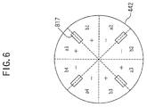
- a plurality of protrusions (comb teeth) 817 for magnifying the displacement of the ultrasonic stator 442, and delivering drive force from the ultrasonic stator 442 to the ultrasonic rotor 434 are provided in a surface of the ultrasonic stator 442. Due to an elastic force of the ultrasonic-motor spring 438, the ultrasonic rotor 434 is pushed onto the protrusions (comb teeth) 817 of the ultrasonic stator 442.
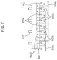
- the ultrasonic stator 442 structuring a vibrator for the ultrasonic motor 430 is bonded, in one surface, with a piezoelectric element 802 formed with two sets of electrode groups 803a, 803b comprising a plurality of electrodes.
- An oscillation drive circuit 825 is connected to the electrode groups 803a, 803b of the piezoelectric element 802.
- An inverter 812 plays an role as an inverter power amplifier to invert and amplify an electric signal as oscillation information, by the electrodes 803c formed on one surface and the other surface formed with the electrode groups 803a, 803b of the piezoelectric element 802 or the ultrasonic stator 442.
- a resistor 813 is connected in parallel with the inverter 812 to stabilize an operation point of the inverter 812.
- An output terminal of the inverter 812 is connected to input terminals of two sets of buffers 811a, 811b through a resistor 814. Output terminals of the two buffers 811a, 811b are respectively connected to the electrode groups 803a, 803b of the piezoelectric element 802.
- a capacitor 815 at one end is connected to an input terminal of the inverter 812, and the capacitor 816 at one end is connected to an output terminal of the inverter 812 through the resistor 814.
- the capacitors 815, 816 at the other ends are ground to perform phase adjustment inside the oscillation drive circuit 825.
- the inverter 812 and the buffers 811a, 811b respectively have control terminals together with the input terminals and output terminals, which are an inverter and buffers of a tri-state configuration capable of bringing the output terminal to a high impedance state depending on a signal inputted to the control terminal.
- a forward-reverse signal generating means 820 outputs to a switch circuit 826 a forward/reverse signal to set a rotation direction of the ultrasonic rotor 434 of the ultrasonic motor 430.
- the output terminals of the switch circuit 826 are respectively connected to the tri-state buffer 811a, 811b of the oscillation drive circuit 825 and to the control terminal of the tri-state inverter 812, to make one of the tri-state buffers 811a, 811b function as a usual buffer on the basis of the output signal of the forward-reverse signal generating means 820, and the output terminal of the other buffer in a high impedance state for disabling.
- the ultrasonic stator 442 is driven by a tri-state buffer to function as a usual buffer selected by an output signal of the switch circuit 826.
- the ultrasonic stator 422 is driven only by a tri-state buffer allowed to function as a usual buffer by the switch circuit 826. If the tri-state buffer allowed to function as a usual buffer is changed by the switch circuit 826, the ultrasonic rotor 434 of the ultrasonic motor 430 is inverted in rotational direction.
- the tri-state inverter in the output terminal can be brought in a high impedance state.
- the tri-state buffers 811a, 811b are both disabled to enable to stop the rotation of the ultrasonic rotor 434 of the ultrasonic motor 430.
- the disc-formed ultrasonic stator 442 is bonded, in its one flat surface, with a disc-formed piezoelectric element 802 through adhesion, thin-film formation or the like.
- Two-wavelength vibration waves e.g. standing waves
- the piezoelectric element 802 is circumferentially formed, in its one flat surface, with alternate 8-divided electrodes that are 4 times relative to the number of waves to provide a first electrode group 803a and a second electrode group 803b, and processed with polarization (+) and (-) as shown in Fig. 6 and 7.
- the first electrode group 803a is constituted by electrodes a1, a2, a3, a4.
- the electrodes are short-circuited by a first connecting means 814a.
- the second electrode group 803b is constituted by electrodes b1, b2, b3, b4.
- the electrodes are short-circuited by a second connecting means 814b.
- (+), (-) in Fig. 6 and Fig. 7 shows a direction of polarization, which is each polarized by applying a positive electric field and negative electric field to a bonding surface side of the piezoelectric element 802 with the ultrasonic stator 442.
- the protrusions (comb teeth) 817 for magnifying the displacement of the ultrasonic stator 442 and conveying drive force from the ultrasonic stator 442 to the ultrasonic rotor 434 are provided in the vicinity of every other boundary of the electrodes.
- a high frequency voltage generated by the oscillation drive circuit 825 is applied to either one of the electrode group 803a or 803b thereby driving the ultrasonic stator 442.
- the rotational direction of the ultrasonic rotor 434 of the ultrasonic motor 430 is switched depending upon which electrode group the ultrasonic stator 442 is driven by.
- the ultrasonic motor used in the invention is preferably driven by the above structure of the drive circuit, piezoelectric element and ultrasonic stator, it is to be driven by other structure.
- a quartz oscillator 210 constitutes source oscillation for a circuit to count time.
- An IC 212 includes a frequency-dividing circuit 214, a corrected-pulse comparator circuit 216, a ultrasonic-motor drive circuit 468, a waveform correcting circuit 332 and a detection-signal frequency dividing circuit 334.
- the frequency-dividing circuit 214 inputs an output signal outputted by oscillation of the quartz oscillator 210 and outputs a signal concerning a time (see (2) of Fig. 8).
- the waveform correcting circuit 332 modifies a waveform of a detection signal outputted by a watch-error detecting section.
- the detection-signal frequency-dividing circuit 334 divides a frequency of a corrected detection signal outputted by the waveform correcting circuit 332.
- the corrected-pulse comparator circuit 216 compares between a frequency-divided signal outputted by the frequency-dividing circuit 214 (see (2) of Fig. 8) and a frequency-divided detection signal outputted by the detection signal frequency dividing circuit 334 (see (1) of Fig. 8).
- the ultrasonic motor drive circuit 468 outputs a ultrasonic-motor drive signal for driving the ultrasonic motor 430 to the ultrasonic motor 430, based on a signal outputted by the corrected-pulse comparator circuit 216.
- a battery 220 constitutes a power source to operate the IC 212.
- the quartz oscillator 210, the frequency-dividing circuit 214 in the IC 212 and the battery 220 constitute a time count section for counting time.
- the train wheel 224 is rotated by the mainspring 222 as a power source.
- the minute hand 226 structurally indicates "minute” and the hour hand 228 indicates "hour”.
- the minute hand 226 is fixed on the second wheel and pinion 124.
- the second wheel and pinion 124 is structured to rotate once per hour.
- the escape wheel and pinion 130 rotates.
- the pallet fork 142 controls the rotation of the escape wheel and pinion 130 based on the operation of the balance with hairspring 140.
- An pallet-fork detecting piezoelectric element 336 is fixed to a first bank pin 102d of the main plate 102. Consequently, the ankle rod portion 142d is structured to contact the pallet-fork detecting piezoelectric element 336. At the instance that the pallet-fork rod portion 142d hits the pallet-fork detecting piezoelectric element 336, the pallet-fork detecting piezoelectric element 336 generates a voltage (see (4) of Fig. 10).
- the pallet-fork detecting piezoelectric element 336 constitutes a watch-error detecting section 330 to detect a rotational operation state of the train wheel.
- a detection signal structurally enter the IC 212. Because the balance with hairspring 140 vibrates at 3 Hertz, the watch-error detecting section 330 at 3 Hertz outputs a detection signal.
- the waveform correcting circuit 332 is configured to input therein a detection circuit outputted by the pallet-fork detecting piezoelectric element 336, and shape a waveform thereof and output a corrected signal to the detection-signal frequency dividing circuit 334.
- the detected-signal frequency dividing circuit 334 is configured to frequency-divide the corrected signal and output a corrected frequency-divided signal to the corrected-pulse comparator circuit 216.
- the corrected-pulse comparator circuit 216 is configured to compare between a period of one hour measured by the escape/speed-control device and a period of one hour measured by the IC 212.
- the watch-error detecting section 330 outputs to the IC 212 a detection signal of one-hour period measured by the escape/speed-control device including the escape wheel and pinion 130, pallet fork 142 and balance with hairspring 140 due to hit of the pallet-fork rod portion 142d to the pallet-fork detecting piezoelectric element 336.
- the watch-error detecting section 330 includes the pallet-fork rod portion 142d and the pallet-fork detecting piezoelectric element 336.
- the frequency-dividing circuit 214 is configured to frequency-divide the 32768-Hz output signal outputted by oscillation of the quartz oscillator 210 and output a frequency-divided signal of one hour period to the corrected-pulse comparator circuit 216.
- the corrected-pulse comparator circuit 216 is configured to compare between a detection signal of one hour period measured by the escape/speed-control device (see (1) of Fig. 8) and a frequency-divided signal of one hour period frequency-divided by the frequency-dividing circuit 214 (see (1) of Fig. 8), and counts a difference between them (see (3) of Fig. 8). This difference is a time to be corrected by correcting a time error in the mechanical timepiece of the invention.
- the ultrasonic-motor drive circuit 468 is configured to output a drive signal to the ultrasonic motor 430 based on a signal corresponding to the difference outputted by the corrected-pulse comparator circuit 216.
- the corrected-pulse comparator circuit 216, the ultrasonic-motor drive circuit 468, the ultrasonic motor 430 and the regulator 420 constitute a watch-error adjusting section to control the operation of the balance with hairspring 140.
- the watch-error adjusting section is configured to control the operation of the train wheel 224 with a period of once per hour to once per day.
- the waveform correcting circuit 332 inputs therein a detection signal outputted by the pallet-fork detecting piezoelectric element 336, and shapes a waveform thereof and outputs a corrected signal to the detection-signal frequency dividing circuit 334.
- the waveform correcting circuit 332 inputs therein a detection signal counted by the pallet-fork detection signal count section and outputs a corrected signal shown in (5) of Fig. 10 to the detection-signal frequency dividing circuit 334.
- the detection-signal frequency dividing circuit 334 frequency-divides 10800 times the corrected signal outputted by the waveform correcting circuit 332 and outputs a corrected frequency-divided signal as shown in (1) of Fig. 8 to the corrected-pulse comparator circuit 216.
- the corrected-pulse comparator circuit 216 compares between a corrected frequency-divided signal outputted by the corrected-pulse comparator circuit 216 and a frequency-divided signal of with a period of one hour of the frequency-divided signal outputted by the frequency-dividing circuit 214, and counts a difference thereof.
- the timing the pallet-fork rod portion 142d hits the pallet-fork detecting piezoelectric element 336 is known and accordingly the timing the pallet fork 142 stops is known. Accordingly, it is possible to detect a rotational direction that the balance with hairspring 140 is rotating from the timing the pallet fork 142 stops.
- the detection-signal frequency dividing circuit 334 frequency-divides a corrected signal 10800 times and outputs a corrected frequency signal to the corrected-pulse comparator circuit 216.
- the corrected-pulse comparator circuit 216 compares between a period of one hour measured by the escape/speed-control device and a period of one hour measured by the IC 212, and determines whether the watch error of the timepiece is fast or the watch error of the timepiece is slow.
- the ultrasonic-motor drive circuit 468 causes the ultrasonic rotor 434 to rotate rightward (forward rotation, clockwise rotation) to rotate the regulator 420 leftward (reverse rotation, counterclockwise rotation) making slow the timepiece watch error.
- the ultrasonic-motor drive circuit 468 causes the ultrasonic rotor 434 to rotate leftward (reverse rotation) to rotate the regulator 420 rightward (forward rotation) making fast the timepiece watch error.
- the rotational direction and rotation angle value that the ultrasonic-motor drive circuit 468 rotates the ultrasonic rotor 434 based on a result of determination of the corrected-pulse comparator circuit 216 is previously determined by experiments in relationship between a watch error of the mechanical timepiece and a position of the regulator 420 and stored in the corrected-pulse comparator circuit 216.
- the corrected-pulse comparator circuit 216, the ultrasonic-motor drive circuit 468, the ultrasonic motor 430 and the regulator 420 constitute a watch-error adjusting section for controlling the operation of the balance with hairspring 140 and adjusting the watch error of the mechanical timepiece.
- This watch-error adjusting section is configured to control the operation of the balance with hairspring 140 with a period of from once per hour to once per day.
- the watch error of the mechanical timepiece can be adjusted with accuracy.
- a regulator 520 is rotatably mounted on the balance with hairspring 166.
- the rotation center of the regulator 520 is the same as a rotation center of the balance with hairspring 140.
- the regulator 520 includes a regulator body 522, a regulator gear 524, a stud bridge 526 and a stud rod 528.
- a bore provided in the rotation center of the regulator body 522 is rotatably fitted in the outer perophery of a balance upper bearing of the hairspring 140.
- the regulator gear 524 is a partly teethed gear (gear having teeth provided not in the entire periphery of an outer periphery but in part of the outer periphery as shown in Fig. 12) provided in an outer periphery of the regulator body 522.
- the mainspring 140c in its portion near the outer periphery is supported between the stud bridge 526 and the stud rod 528. Consequently, by rotating the regulator 520 to position the stud bridge 526 and stud rod 528, an effective length of the mainspring 140c is determined. If the effective length of the stud mainspring 140c, a period of rotation of the balance with hairspring 140 is determined to determine a watch error of the mechanical timepiece.
- a step motor 530 is mounted on the main plate 102.
- the step motor 530 has a stator 532, a rotor 534 and a coil block 536.
- a rotor pinion 534k is integrally formed with the rotor 534.
- a rotor transmission wheel 540 is rotatably assembled on the main plate 102.
- the rotor transmission wheel 540 includes a rotor transmission gear 542 and a rotor transmission pinion 544.
- the rotor transmission gear 542 is in mesh with the rotor pinion 534k.
- the rotor transmission pinion 544 is in mesh with the regulator gear 524.
- the rotor transmission wheel 540 rotates.
- the regulator gear 424 rotates.
- the rotor transmission wheel 540 constitutes a reduction train wheel.
- the IC 572 includes a frequency dividing circuit 574 to inputs an output signal outputted due to vibration of the quartz oscillator 210 and frequency-divide the signal to output a signal concerning a time, a corrected-pulse comparator circuit 576 to compare a corrected pulse, a step-motor drive circuit 568 to output a drive signal for driving the step motor 530, a waveform correcting circuit 332 to correct a waveform of a detection signal and a detection-signal frequency dividing circuit 334 to frequency-divide a detection signal.
- a battery 220 constitutes a power supply to operate the IC 572.
- the quartz oscillator 210, the frequency-dividing circuit 574 in the IC 572 and the battery 220 constitute a time count section to count time.
- the step motor drive circuit 568 causes the rotor 534 to rotate leftward (reverse rotation) to rotate the regulator 420 leftward (reverse rotation) making slow the watch error of the timepiece.
- the step motor drive circuit 568 causes the rotor 534 to rotate rightward (forward rotation) to rotate the regulator 420 rightward (forward rotation) making fast the watch error of the timepiece.
- the value of rotation direction and rotation angle that the step-motor drive circuit 568 rotates the rotor 534 based on a result of determination of the corrected-pulse comparator circuit 576 is previously determined by experiments in relationship between a watch error of the mechanical timepiece and a position of the regulator 520 and stored in the corrected-pulse comparator circuit 576.
- the corrected-pulse comparator circuit 576, the step-motor drive circuit 568, the step motor 530, the rotor transmission wheel 540 and regulator 520 constitute a watch-error adjusting section 550 to control the operation of the balance with hairspring 140 and adjust a watch error of the mechanical timepiece.
- This watch-error adjusting section 550 is configured to control the operation of the balance with hairspring 140 with a period of from once per hour to once per day.
- the configuration of the step-motor drive circuit 568 is simpler than the configuration of the above-stated ultrasonic-motor drive circuit 468 and the structure of the step motor 530 is simpler than the structure of the above-stated ultrasonic motor 430.
- the circuits performing various functions may be configured in the IC and the IC may be a PLA-IC incorporating a program to carry out various operations.
- external elements such as resistors, capacitors, coils, diodes and transistors together with the IC.
- the mechanical timepiece of the present invention is suitable for manufacturing a high-accuracy mechanical timepiece.
- the vibration period of the balance with hairspring is varied making possible to accurately adjust the watch error.
Landscapes
- Physics & Mathematics (AREA)
- General Physics & Mathematics (AREA)
- General Electrical Machinery Utilizing Piezoelectricity, Electrostriction Or Magnetostriction (AREA)
Abstract
A mechanical timepiece of the present invention has a
movement structured having a mainspring constituting a
power source for the mechanical timepiece, a train wheel
rotating due to a rotation force of the mainspring upon
being rewound, an escape/speed-control device for
controlling rotation of the train wheel, the escape/speed-control
device including a balance with hairspring
alternately repeating right and left rotation, an escape
wheel and pinion rotating based on rotation of the train
wheel and a pallet fork controlling rotation of the escape
wheel and pinion based on operation of the balance with
hairspring. The balance with hairspring includes a stud
mainspring, a stud stem and a stud wheel.
The mechanical timepiece of the invention further
comprises a time count section to count time having a
quartz oscillator constituting source oscillation, an IC
including a frequency-dividing section to input an output
signal outputted due to oscillation of said quartz
oscillator and output a signal concerning a time by
frequency-dividing the signal, and a power source to
operate said IC; a watch error section for detecting a
watch error of said mechanical timepiece; and a watch-error
adjusting section including a regulator operating
based on a count signal counted by said time count section
and an operation state signal representative of a watch
error detected by said watch-error detecting section. The
regulator is rotated by the motor based on a operation
state signal. With this structure, the vibration period
of the balance with hairspring can be varied making
possible to accurately adjust the watch error of the
mechanical timepiece.
Description
The present invention relates to a mechanical
timepiece capable of indicating time with accuracy.
The invention relates, more specifically, to a
mechanical timepiece with regulator rotation mechanism
having a mechanism capable of operating the regulator to
adjust a timepiece watch error.
In the conventional mechanical timepiece, as shown in
Fig. 14 and Fig. 15 the mechanical-timepiece movement 1100
(mechanical body) has a main plate 1102 constituting a
base plate for the movement. A hand setting stem 1110 is
rotatably assembled in a hand-setting-stem guide hole
1102a of the main plate 1102. A dial 1104 (shown by the
virtual line in Fig. 15) is attached to the movement 1100.
Generally, of the both sides of a main plate, the
side having a dial is referred to as a "back side" of the
movement and the opposite side to the side having the dial
as a "front side". The train wheel assembled on the
"front side" of the movement is referred to as a "front
train wheel" and the train wheel assembled on the "back
side" of the movement is as a "back train wheel".
The hand setting stem 1110 is determined in axial
position by a switch device including a setting lever
1190, a yoke 1192, a yoke spring 1194 and a back holder
1196. A winding pinion 1112 is rotatably provided on a
guide axis portion of the hand setting stem 1110. When
rotating the hand setting stem 1110 in a state the hand
setting stem 1110 is in a first hand-setting-stem position
closest to an inward of the movement along a rotation axis
direction (0 stage), the winding pinion 1112 rotates
through rotation of the clutch wheel. A crown wheel 1114
rotates due to rotation of the winding pinion 1112. A
ratchet wheel 1116 rotates due to rotation of the crown
wheel 1114. By rotating the ratchet wheel 1116, a
mainspring 1122 accommodated in a barrel complete 1120 is
wound up. A center wheel and pinion 1124 rotates due to
rotation of the barrel complete 1120. An escape wheel and
pinion 1130 rotates through rotation of a fourth wheel and
pinion 1128, third wheel and pinion 1126 and center wheel
and pinion 1124. The barrel complete 1120, center wheel
and pinion 1124, third wheel and pinion 1126 and fourth
wheel and pinion 1128 constitutes a front train wheel.
An escapement/speed-control device for controlling
rotation of the front train wheel includes a balance with
hairspring 1140, an escape wheel and pinion 1130 and
pallet fork 1142. The balance with hairspring 1140
includes a balance stem 1140a, a balance wheel 1140b and a
stud mainspring 1140c. Based on the center wheel and
pinion 1124, an hour pinion 1150 rotates simultaneously.
A minute hand 1152 attached on the hour wheel 1150
indicates "minute". The hour pinion 1150 is provided with
a slip mechanism for the center wheel and pinion 1124.
Based on rotation of the hour pinion 1150, an hour wheel
1154 rotates through rotation of a minute wheel. An hour
hand 1156 attached on the hour wheel 1154 indicates
"hour".
The barrel complete 1120 is rotatably supported
relative to the main plate 1102 and barrel bridge 1160.
The center wheel and pinion 1124, the third wheel and
pinion 1126, the fourth wheel and pinion 1128 and the
escape wheel and pinion 1130 are rotatably supported
relative to the main plate 1102 and train wheel bridge
1162. The pallet fork 1142 is rotatably supported
relative to the main plate 1102 and pallet fork bridge
1164. The balance with hairspring 1140 is rotatably
supported relative to the main plate 1102 and balance
bridge 1166.
The stud mainspring 1140c is a thin leaf spring in a
spiral (helical) form having a plurality of turns. The
stud mainspring 1140c at an inner end is fixed to a stud
ball 1140d fixed on the balance stem 1140a, and the stud
mainspring 1140c at an outer end is fixed by screwing
through a stud support 1170a attached to a stud bridge
1170 fixed on the balance bridge 1166.
A regulator 1168 is rotatably attached on the balance
bridge 1166. A stud bridge 1168a and a stud rod 1168b are
attached on the regulator 1168. The stud mainspring 1140c
has a portion close to the outer end positioned between
the stud bridge 1168a and the stud rod 1168b.
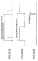
Generally, in the conventional representative
mechanical timepiece, as shown in Fig. 16 the torque on
the mainspring decreases while being rewound as the
sustaining time elapses from a state the mainspring is
fully wound (full winding state). For example, in the
case of Fig. 16, the mainspring torque in the full winding
state is about 27 g·cm, which becomes about 23 g·cm at a
lapse of 20 hours from the full winding state and about 18
g·cm at a lapse of 40 hours from the full winding state.
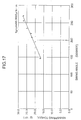
Generally, in the conventional representative
mechanical timepiece, as shown in Fig. 17 the decrease of
mainspring torque also decreases a swing angle of the
balance with hairspring. For example, in the case of Fig.
17, the swing angle of the balance with hairspring is
approximately 240 to 270 degrees when the mainspring
torque is 25 to 28 g·cm while the swing angle of the
balance with hairspring is approximately 180 to 240
degrees when the mainspring torque is 20 to 25 g·cm.
Referring to Fig. 18, there is shown transition of an
instantaneous watch error (numeral value indicative of
timepiece accuracy) against a swing angle of a balance
with hairspring in the conventional representative
mechanical timepiece. Here, "instantaneous watch error"
refers to "a value representative of fast or slow of a
mechanical timepiece at a lapse of one day on the
assumption that the mechanical timepiece is allowed to
stand while maintaining a state or environment of a swing
angle of a balance with hairspring upon measuring a watch
error". In the case of Fig. 18, the instantaneous watch
error delays when the swing angle of the balance with
hairspring is 240 degrees or greater or 200 degrees or
smaller.
For example, in the conventional representative
mechanical timepiece, as shown in Fig. 18 the
instantaneous watch error is about 0 to 5 seconds per day
(about 0 to 5 seconds fast per day) when the swing angle
of the balance with hairspring is about 200 to 240 degrees
while the instantaneous watch error becomes about -20
seconds per day (about 20 seconds slow per day) when the
swing angle of the balance with hairspring is about 170
degrees.
Referring to Fig. 19, there is shown a transition of
an instantaneous watch error and a lapse time upon
rewinding the mainspring from a full winding state in the
conventional representative mechanical timepiece. Here,
in the conventional mechanical timepiece, the "watch
error" indicative of timepiece advancement per day or
timepiece delay per day is shown by an extremely thin line
in Fig. 19, which is obtainable by integrating over 24
hours an instantaneous watch error against a lapse time of
rewinding the mainspring from the full winding.
Generally, in the conventional mechanical timepiece,
the instantaneous watch error slows down because the
mainspring torque decreases and the balance-with-hairspring
swing angle decreases as the sustaining time
elapses with the mainspring being rewound from a full
winding state. Due to this, in the conventional
mechanical timepiece, the instantaneous watch error in a
mainspring full winding state is previously put forward in
expectation of timepiece delay after lapse of a sustaining
time of 24 hours, thereby previously adjusting plus the
"watch error" representative of timepiece advancement or
delay per day.
For example, in the conventional representative
mechanical timepiece, as shown by an extreme thin line in
Fig. 19 the instantaneous watch error in a full winding
state is about 3 seconds per day (3 seconds fast per day).
However, when 20 hour elapses from the full winding state,
the instantaneous watch error becomes about -3 seconds per
day (about 3 seconds slow per day). When 24 hours elapses
from the full winding state, the instantaneous watch error
becomes about -8 seconds per day (about 8 seconds slow per
day). When 30 hours elapses from the full winding state,
the instantaneous watch error becomes about -16 seconds
per day (about 16 seconds slow per day).
In the conventional mechanical timepieces, the
timepiece accuracy has been determined by an accuracy of
operating the escape/speed-control device including a
balance with hairspring to repeat right and left rotation,
an escape wheel and pinion to rotate based on rotation of
the train wheel and a pallet fork to control rotation of
the escape wheel and pinion based on the operation of the
balance with hairspring.
Accordingly, in order to enhance the timepiece
accuracy, the vibration period of the balance with
hairspring must be increased. It has been impossible to
manufacture an escape/speed-control device including such
a balance with hairspring.
Moreover, in the conventional mechanical timepieces,
there is limitation in range that the timepiece accuracy
is to be improved. Consequently, there has been a problem
that the limit the timepiece accuracy is to be improved is
delimited.
Accordingly, the conventional mechanical timepieces
have been worse in accuracy than the accuracy of the
quartz-type timepieces. Consequently, the conventional
timepiece's users must have corrected time indicated by
the mechanical timepiece.
Therefore, it is an object of the present invention
to provide a mechanical timepiece extremely high in
accuracy.
Also, another object of the invention is to provide
an accurate mechanical timepiece that can be used over a
long term.
A mechanical timepiece of the present invention has a
movement structured having a mainspring constituting a
power source for the mechanical timepiece, a train wheel
rotating due to a rotation force of the mainspring upon
being rewound, an escape/speed-control device for
controlling rotation of the train wheel, the escape/speed-control
device including a balance with hairspring
alternately repeating right and left rotation, an escape
wheel and pinion rotating based on rotation of the train
wheel and a pallet fork controlling rotation of the escape
wheel and pinion based on operation of the balance with
hairspring, the balance with hairspring including a stud
mainspring, a stud stem and a stud wheel.
The mechanical timepiece of the invention comprises a
time count section to count time having a quartz
oscillator constituting source oscillation, an IC
including a frequency-dividing section to input an output
signal outputted due to oscillation of said quartz
oscillator and output a signal concerning a time by
frequency-dividing the signal, and a power source to
operate said IC; a watch error section for detecting a
watch error of said mechanical timepiece; and a watch-error
adjusting section including a regulator operating
based on a count signal counted by said time count section
and an operation state signal representative of a watch
error detected by said watch-error detecting section. By
rotating the regulator based on an operation state signal
in this manner, the vibration period of the balance with
hairspring is varied making possible to accurately adjust
the watch error of the mechanical timepiece.
In the mechanical timepiece of the invention, the
power source is a primary battery, such as for example a
silver battery or a lithium battery. The power source may
be a solar battery, a chargeable secondary battery or a
chargeable capacitor. Furthermore, the mechanical
timepiece of the invention may be provided with an
automatic power generation section.
Also, said watch-error adjusting section of the
mechanical timepiece of the invention is preferably
configured to operate said regulator with a period of from
once per hour to once per day.
Also, said watch-error detecting section of the
mechanical timepiece of the invention preferably includes
a pallet-fork detecting piezoelectric element provided on
a bank pin to detect operation of said pallet fork, and a
pallet-fork signal count section to count pallet-fork
detection signals outputted by said pallet-fork detecting
piezoelectric element.
Also, said watch-error adjusting section of the
mechanical timepiece of the invention preferably includes
a regulator rotating due to rotation of an ultrasonic
motor. With this structure, the regulator can be
positively rotated without providing a reduction train
wheel. This can accurately adjust the watch error of the
mechanical timepiece.
Also, the watch-error adjusting section of the
mechanical timepiece of the invention may be structured
including a regulator to rotate through a reduction train
wheel due to rotation of a step motor. With this
structure, the regulator can be positively rotated by a
simple part structure and circuit configuration. This can
accurately adjust the watch error of the mechanical
timepiece.
In the usual analogue quartz timepiece, used are a
battery, quartz, an IC, a motor, a train wheel, hands and
so on. In such an analogue quartz timepiece, the energy
possessed by the battery is used to operate the quartz and
IC to measure time and rotate the motor to indicate time.
The energy used to operate the quarts and IC to measure
the IC and the energy used to rotate the motor to indicate
time are in a ratio of approximately 3:7. Accordingly, in
the analogue quartz timepiece, if only the function to
measure time is used, the life of the battery will
increase to three times or longer. In the usual analogue
quartz timepiece, because the battery life is
approximately two years, if a battery having the same
shape as the usual analogue quartz timepiece is used, the
battery can be used for six years or longer.
Also, the usual mechanical timepiece can be used for
about five years without any repair. If overhaul is made
after five years from the beginning of use, it can be used
further about five years. Accordingly, the usual
mechanical timepiece, if overhauled once, can be used for
approximately ten years.
Accordingly, in the mechanical timepiece of the
invention, if a battery, quartz and IC similar to the
usual analog quartz timepiece are used, there is no
necessity of replacing the battery to a time when there is
a need of conducting overhaul. Furthermore, in the
mechanical timepiece of the invention, if the capacity of
the battery is increased to decrease the power consumption
of the IC, it is possible to obtain a timepiece without
requiring battery replacement before the life of the
mechanical structural part runs out.
Also, in the mechanical timepiece of the invention,
because the timepiece operates due to a mechanical
structure, even if the life of the battery runs out, there
is no fear that the timepiece stops. The accuracy of time
indication merely worsens than that the battery life runs
out.
Incidentally, in the mechanical timepiece, if a power
generator mechanism and chargeable power source is
mounted, there becomes no fear that the battery life runs
out.
Hereunder, embodiments of a mechanical timepiece of
the present invention will be explained based on the
drawings.
Referring to Fig. 1 and Fig. 2, in a first embodiment
of a mechanical timepiece of the invention, a movement 400
of the mechanical timepiece has a main plate 102
structuring a base plate for the movement. A hand-setting
stem 110 is rotatably assembled in a winding-stem guide
hole 102a of the main plate 102.
A dial (not shown) is attached on the movement 400 of
the mechanical timepiece of the invention. The dial is
provided, for example, with a 12:00 division, 3:00
division, 6:00 division and 9:00 division.
The hand-setting stem 110 has a squared portion and a
guide shaft portion. A clutch wheel (not shown) is
assembled on the square portion of the hand setting stem
110. The clutch wheel has a same rotation axis as a
rotation axis of the hand setting stem 110. That is, the
clutch wheel is provided having a squared hole and rotated
based on rotation of the hand setting stem 110 by fitting
the squared hole on the squared portion of the hand
setting stem 110. The clutch wheel has teeth A and teeth
B. The teeth A are provided in the clutch wheel at an end
close to a center of the movement. The teeth B are
provided in the clutch wheel at an end close to an outside
of the movement.
The movement 400 is provided with a switch device to
determine an axial position of the winding stem 110. The
switch device includes a setting lever 132, a yoke 134, a
yoke spring 136 and a setting lever jumper 136. The hand-setting
stem 110 is determined in rotational axial
position based on rotation of the setting lever 132. The
clutch wheel is determined in rotation-axis position based
on rotation of the yoke 134. The yoke 134 is to be
determined at two positions in rotational direction based
on rotation of the setting lever 132.
A winding pinion 112 is rotatably provided on the
guide shaft portion of the hand setting stem 110. When
the hand setting stem 110 in a state at a first hand
setting stem 110 is positioned closest to a movement 400
inner side along the rotation axis direction (in a 0
stage), the winding pinion 112 is structurally rotated
through rotation of the clutch wheel. A crown wheel 114
is assembled to rotate due to rotation of the winding
pinion 112. A ratchet wheel 116 is assembled to rotate
due to rotation of the crown wheel 114.
The movement 400 has as a power source a mainspring
(not shown) accommodated in a barrel complete 120. The
mainspring is made of an elastic material having
springiness, such as iron. The mainspring is structured
for rotation due to rotation of the ratchet wheel 116.
A center wheel and pinion 124 is assembled for
rotation due to rotation of the barrel complete 120. A
third wheel and pinion 126 is assembled rotatable based on
rotation of the center wheel and pinion 124. A fourth
wheel and pinion 128 is assembled rotatable based on
rotation of the third wheel and pinion 126. An escape
wheel and pinion 130 is assembled for rotation due to
rotation of the fourth wheel and pinion 128. The barrel
complete 120, the center wheel and pinion 124, the third
wheel and pinion 126 and the fourth wheel and pinion 128
constitute a front train wheel.
The movement 400 has an escapement/governing device
assembled therein to control rotation of the front train
wheel. The escapement/governing device includes a balance
with hairspring 140 to repeat right and left rotation with
a constant period, an escape wheel and pinion 130 to
rotate based on rotation of the front train wheel, and
pallet fork 142 to control rotation of the escape wheel
and pinion 130 based on the operation of the balance with
hairspring 140.
Basic principles of operation of pinion 130, pallet
fork 142, and hairspring 140 are same as conventional
movement of mechanical timepiece.
Referring to Fig. 9, the pallet fork 142 has an entry
pallet 142a provided contactable with the escape wheel and
pinion 130, an exit pallet 142b provided contactable with
the escape wheel and pinion 130, a pallet-fork guard pin
142c provided such that a balance-with hairspring roller
jewel (not shown) enters and leaves, and a pallet-fork rod
142d.
If the balance with hairspring and roller jewel
rotates leftward (counterclockwise), the roller jewel
enters the pallet-fork guard pin 142c. Thereupon, the
roller jewel causes the pallet fork 142 rightward
(clockwise) and stops/releases it on the entry pallet 142a
side. Thereupon, a locking corner of the escape wheel and
pinion 130 moves to an impact surface of the entry pallet
142a. The force of the escape wheel and pinion 130 pushes
up the impact surface of the entry pallet 142a and rotates
the pallet fork 142 rightward (clockwise). Thereupon, the
pallet-fork guard pin 142c pushes the roller jewel and
rotates the roller jewel leftward (counterclockwise).
After the impact has ended, the tooth of the escape
wheel and pinion 130 leaves the entry pallet 142a so that
the escape wheel and pinion 130 races and the escape wheel
and pinion 130 falls down. After ending the fall down of
the escape wheel and pinion 130, another tooth of the
escape wheel and pinion 130 hits a stop surface of the
exit pallet 142b into a first halt state.
After ending the first halt state, when the roller
jewel leaves the pallet-fork guard pin 142c, the pallet
fork 142 causes the roller jewel to rotate leftward
(counterclockwise) due to the force of the escape wheel
and pinion 130. Then, the pallet-fork rod 142d contacts a
first bank pin 102d of the main plate, and the pallet fork
142 ceases in rotation into a second halt state.
Then, the balance with hairspring 140 rotates
leftward (counterclockwise) and freely vibrates.
Next, when the balance with hairspring 140 reaches a
maximum deflection angle position, the balance with
hairspring 140 rotates rightward (clockwise) and the
roller jewel also rotates rightward (clockwise).
Thereupon, the roller jewel contacts the pallet-fork
guard pin 142c and the pallet fork 142 rotates leftward
(counterclockwise). Thereupon, this is halted and
released on the side of the exit pallet 142b and repeats
the same operation as that of the exit pallet 142b on the
entry pallet 142a side.
Referring again to Fig. 1 and Fig. 2, based on
rotation of the second wheel and pinion 124, a cannon
pinion (not shown) simultaneously rotates. A minute hand
(not shown) mounted on the cannon pinion is structured to
indicate "minute". The canon pinion is provided with a
slip mechanism having a predetermined slop torque to the
second wheel and pinion 124.
Based on rotation of the cannon pinion, minute wheel
(not shown) rotates. Based on rotation of the minute
wheel, an hour wheel (not shown) rotates. An hour hand
(not shown) mounted on the hour wheel is structured to
indicate "hour".
The barrel complete 120 is supported rotatable
relative to the main plate 102 and barrel bridge 160. The
second wheel and pinion 124, third wheel and pinion 126,
fourth wheel and pinion 128 and escape wheel and pinion
130 is supported rotatable relative to the main plate 102
and train wheel bridge 162. The pallet fork 142 is
supported rotatable relative to the main plate 102 and
pallet bridge 164.
The balance with hairspring 140 is supported
rotatable relative to the main plate 102 and balance
bridge 166. That is, an upper tenon of the balance stem
140a is supported rotatable relative to a balance upper
bearing fixed on the balance bridge 166. The balance
upper bearing includes a balance upper hole jewel and a
balance upper cap jewel. The balance upper hole jewel and
balance upper cap jewel is made of an insulation material
such as ruby. The balance with hairspring 140 includes a
balance stem 140a, a balance wheel 140b and mainspring
140c.
A lower tenon of the balance stem 140a is supported
rotatable relative to a balance lower bearing fixed on the
main plate 102. The balance lower bearing includes a
balance lower hole jewel and a balance lower cap jewel.
The balance lower hole jewel and balance lower cap jewel
is made of an insulation material such as ruby.
The stud mainspring 140c is a thin leaf spring in a
spiral form (helical form) having a plurality of turns.
An inner end of the stud mainspring 140c is fixed to a
stud ball fixed on the balance stem 140a, and an outer end
of the stud mainspring 140c is screw-fixed through a stud
holder attached to a stud bridge 166a rotatably fixed on
the balance bridge 166. The balance bridge 166 is made of
a metal conductive material such as brass. The stud
bridge 166a is made of a metal conductive material such as
iron.
The stud mainspring 140c expands and contracts
radially of the stud mainspring 140c depending on a
rotation angle of the balance with hairspring 140 in
rotation. For example, in a state shown in Fig. 1, when
the balance with hairspring 140 rotates clockwise, the
stud mainspring 140c contracts in a direction toward a
center of the balance with hairspring 140. Contrary to
this, when the balance with hairspring 140 rotates
counterclockwise, the stud mainspring 140c expands in a
direction away from the center of the balance with
hairspring 140.
The stud mainspring 140c is made of an elastic
material having springiness such as "elinvar". That is,
the stud mainspring 140c is made of a metal conductive
material.
A regulator 420 is rotatably mounted on the balance
bridge 166. A rotation center of the regulator 420 is the
same as a rotation center of the balance with hairspring
140. The regulator 420 includes a regulator body 422, a
regulator gear 424, a stud bridge 426 and a stud rod 428.
A bore provided in a rotation center of the regulator body
422 rotatably fit on an outer periphery of the upper
bearing of the balance with hairspring 140. The regulator
gear 424 is a partly teethed gear which is provided on the
outer periphery of the regulator body 422 (gear structured
having teeth provided not on the entire outer periphery
but in part of the outer periphery, see Fig. 1).
The stud mainspring 140c at a portion near the outer
periphery is supported between the stud bridge 426 and the
stud rod 428. Consequently, by rotating the regulator 420
and determining a position of the stud bridge 426 and stud
rod 428, an effective length of the stud mainspring 140c
is determined. If an effective length of the stud
mainspring 140c is determined, a rotation period of the
balance with hairspring 140 is determined, determining a
watch error of the mechanical timepiece.
Next, explanation will be made on the structure and
operation of a ultrasonic motor.
An ultrasonic motor 410 is mounted on the main plate
102. For example, the ultrasonic motor 410 at an outer
periphery is fitted in a ultrasonic-motor assembling bore
of the main plate 102.
Referring to Fig. 2 and Fig. 4, the ultrasonic motor
430 has a housing 432, an ultrasonic rotor 434, an
ultrasonic-motor pinion 436 and an ultrasonic-motor spring
438. An ultrasonic stator 442 is fixed on an ultrasonic-stator
shaft 444. The ultrasonic-stator shaft 444 is
fixed to the housing 432. The ultrasonic-motor pinion 436
is integrally formed with the ultrasonic rotor 434.
Consequently, by rotating the ultrasonic motor 434, the
ultrasonic-motor pinion 436 rotates. The regulator gear
424 is in mesh with the ultrasonic-motor pinion 436.
Consequently, by rotating the ultrasonic rotor 434 and
ultrasonic-motor pinion 436, the regulator gear 424
rotates.
A plurality of protrusions (comb teeth) 817 for
magnifying the displacement of the ultrasonic stator 442,
and delivering drive force from the ultrasonic stator 442
to the ultrasonic rotor 434 are provided in a surface of
the ultrasonic stator 442. Due to an elastic force of the
ultrasonic-motor spring 438, the ultrasonic rotor 434 is
pushed onto the protrusions (comb teeth) 817 of the
ultrasonic stator 442.
Referring to Fig. 4 and Fig. 5, the ultrasonic stator
442 structuring a vibrator for the ultrasonic motor 430 is
bonded, in one surface, with a piezoelectric element 802
formed with two sets of electrode groups 803a, 803b
comprising a plurality of electrodes. An oscillation
drive circuit 825 is connected to the electrode groups
803a, 803b of the piezoelectric element 802. An inverter
812 plays an role as an inverter power amplifier to invert
and amplify an electric signal as oscillation information,
by the electrodes 803c formed on one surface and the other
surface formed with the electrode groups 803a, 803b of the
piezoelectric element 802 or the ultrasonic stator 442. A
resistor 813 is connected in parallel with the inverter
812 to stabilize an operation point of the inverter 812.
An output terminal of the inverter 812 is connected
to input terminals of two sets of buffers 811a, 811b
through a resistor 814. Output terminals of the two
buffers 811a, 811b are respectively connected to the
electrode groups 803a, 803b of the piezoelectric element
802. A capacitor 815 at one end is connected to an input
terminal of the inverter 812, and the capacitor 816 at one
end is connected to an output terminal of the inverter 812
through the resistor 814. The capacitors 815, 816 at the
other ends are ground to perform phase adjustment inside
the oscillation drive circuit 825.
The inverter 812 and the buffers 811a, 811b
respectively have control terminals together with the
input terminals and output terminals, which are an
inverter and buffers of a tri-state configuration capable
of bringing the output terminal to a high impedance state
depending on a signal inputted to the control terminal.
A forward-reverse signal generating means 820 outputs
to a switch circuit 826 a forward/reverse signal to set a
rotation direction of the ultrasonic rotor 434 of the
ultrasonic motor 430. The output terminals of the switch
circuit 826 are respectively connected to the tri-state
buffer 811a, 811b of the oscillation drive circuit 825 and
to the control terminal of the tri-state inverter 812, to
make one of the tri-state buffers 811a, 811b function as a
usual buffer on the basis of the output signal of the
forward-reverse signal generating means 820, and the
output terminal of the other buffer in a high impedance
state for disabling.
The ultrasonic stator 442 is driven by a tri-state
buffer to function as a usual buffer selected by an output
signal of the switch circuit 826. The ultrasonic stator
422 is driven only by a tri-state buffer allowed to
function as a usual buffer by the switch circuit 826. If
the tri-state buffer allowed to function as a usual buffer
is changed by the switch circuit 826, the ultrasonic rotor
434 of the ultrasonic motor 430 is inverted in rotational
direction.
By an output signal from the switch circuit 826
outputted based on an output from the forward-reverse
signal generating means 820, the tri-state inverter in the
output terminal can be brought in a high impedance state.
When the tri-state inverter is disabled, the tri-state
buffers 811a, 811b are both disabled to enable to stop the
rotation of the ultrasonic rotor 434 of the ultrasonic
motor 430.
Referring to Fig. 6 and Fig. 7, the disc-formed
ultrasonic stator 442 is bonded, in its one flat surface,
with a disc-formed piezoelectric element 802 through
adhesion, thin-film formation or the like. Two-wavelength
vibration waves (e.g. standing waves) are oscillated
circumferentially of the ultrasonic stator 442 to
rotationally drive the ultrasonic rotor 434. The
piezoelectric element 802 is circumferentially formed, in
its one flat surface, with alternate 8-divided electrodes
that are 4 times relative to the number of waves to
provide a first electrode group 803a and a second
electrode group 803b, and processed with polarization (+)
and (-) as shown in Fig. 6 and 7.
The first electrode group 803a is constituted by
electrodes a1, a2, a3, a4. The electrodes are short-circuited
by a first connecting means 814a. The second
electrode group 803b is constituted by electrodes b1, b2,
b3, b4. The electrodes are short-circuited by a second
connecting means 814b.
(+), (-) in Fig. 6 and Fig. 7 shows a direction of
polarization, which is each polarized by applying a
positive electric field and negative electric field to a
bonding surface side of the piezoelectric element 802 with
the ultrasonic stator 442.
The protrusions (comb teeth) 817 for magnifying the
displacement of the ultrasonic stator 442 and conveying
drive force from the ultrasonic stator 442 to the
ultrasonic rotor 434 are provided in the vicinity of every
other boundary of the electrodes.
A high frequency voltage generated by the oscillation
drive circuit 825 is applied to either one of the
electrode group 803a or 803b thereby driving the
ultrasonic stator 442. The rotational direction of the
ultrasonic rotor 434 of the ultrasonic motor 430 is
switched depending upon which electrode group the
ultrasonic stator 442 is driven by.
Although the ultrasonic motor used in the invention
is preferably driven by the above structure of the drive
circuit, piezoelectric element and ultrasonic stator, it
is to be driven by other structure.
Next, explanation will be made on the structure and
operation of a time-count section of the mechanical
timepiece of the invention.
Referring to Fig. 3, a quartz oscillator 210
constitutes source oscillation for a circuit to count
time. An IC 212 includes a frequency-dividing circuit
214, a corrected-pulse comparator circuit 216, a
ultrasonic-motor drive circuit 468, a waveform correcting
circuit 332 and a detection-signal frequency dividing
circuit 334.
The frequency-dividing circuit 214 inputs an output
signal outputted by oscillation of the quartz oscillator
210 and outputs a signal concerning a time (see (2) of
Fig. 8). The waveform correcting circuit 332 modifies a
waveform of a detection signal outputted by a watch-error
detecting section. The detection-signal frequency-dividing
circuit 334 divides a frequency of a corrected
detection signal outputted by the waveform correcting
circuit 332.
The corrected-pulse comparator circuit 216 compares
between a frequency-divided signal outputted by the
frequency-dividing circuit 214 (see (2) of Fig. 8) and a
frequency-divided detection signal outputted by the
detection signal frequency dividing circuit 334 (see (1)
of Fig. 8). The ultrasonic motor drive circuit 468
outputs a ultrasonic-motor drive signal for driving the
ultrasonic motor 430 to the ultrasonic motor 430, based on
a signal outputted by the corrected-pulse comparator
circuit 216.
A battery 220 constitutes a power source to operate
the IC 212. The quartz oscillator 210, the frequency-dividing
circuit 214 in the IC 212 and the battery 220
constitute a time count section for counting time.
Next, explanation will be made on the structure and
operation of a watch-error detecting section of the
mechanical timepiece of the invention.
Next, referring to Fig. 1, Fig. 2, Fig. 3 and Fig. 9,
the train wheel 224 is rotated by the mainspring 222 as a
power source. By the rotation of the train wheel 224, the
minute hand 226 structurally indicates "minute" and the
hour hand 228 indicates "hour". The minute hand 226 is
fixed on the second wheel and pinion 124. The second
wheel and pinion 124 is structured to rotate once per
hour. By the rotation of the train wheel 224, the escape
wheel and pinion 130 rotates. The pallet fork 142
controls the rotation of the escape wheel and pinion 130
based on the operation of the balance with hairspring 140.
An pallet-fork detecting piezoelectric element 336 is
fixed to a first bank pin 102d of the main plate 102.
Consequently, the ankle rod portion 142d is structured to
contact the pallet-fork detecting piezoelectric element
336. At the instance that the pallet-fork rod portion
142d hits the pallet-fork detecting piezoelectric element
336, the pallet-fork detecting piezoelectric element 336
generates a voltage (see (4) of Fig. 10).
The pallet-fork detecting piezoelectric element 336
constitutes a watch-error detecting section 330 to detect
a rotational operation state of the train wheel. When the
pallet-fork rod portion 142d hits the pallet-fork
detecting piezoelectric element 336, a detection signal
structurally enter the IC 212. Because the balance with
hairspring 140 vibrates at 3 Hertz, the watch-error
detecting section 330 at 3 Hertz outputs a detection
signal.
The waveform correcting circuit 332 is configured to
input therein a detection circuit outputted by the pallet-fork
detecting piezoelectric element 336, and shape a
waveform thereof and output a corrected signal to the
detection-signal frequency dividing circuit 334.
The detected-signal frequency dividing circuit 334 is
configured to frequency-divide the corrected signal and
output a corrected frequency-divided signal to the
corrected-pulse comparator circuit 216.
Referring to Fig. 3, the corrected-pulse comparator
circuit 216 is configured to compare between a period of
one hour measured by the escape/speed-control device and a
period of one hour measured by the IC 212.
The watch-error detecting section 330 outputs to the
IC 212 a detection signal of one-hour period measured by
the escape/speed-control device including the escape wheel
and pinion 130, pallet fork 142 and balance with
hairspring 140 due to hit of the pallet-fork rod portion
142d to the pallet-fork detecting piezoelectric element
336.
That is, the watch-error detecting section 330
includes the pallet-fork rod portion 142d and the pallet-fork
detecting piezoelectric element 336.
Next, explanation will be made on the structure and
operation of a watch-error adjusting section of a
mechanical timepiece of the invention.
Further, referring to Fig. 1, Fig. 2, Fig. 3 and Fig.
9, the frequency-dividing circuit 214 is configured to
frequency-divide the 32768-Hz output signal outputted by
oscillation of the quartz oscillator 210 and output a
frequency-divided signal of one hour period to the
corrected-pulse comparator circuit 216.
The corrected-pulse comparator circuit 216 is
configured to compare between a detection signal of one
hour period measured by the escape/speed-control device
(see (1) of Fig. 8) and a frequency-divided signal of one
hour period frequency-divided by the frequency-dividing
circuit 214 (see (1) of Fig. 8), and counts a difference
between them (see (3) of Fig. 8). This difference is a
time to be corrected by correcting a time error in the
mechanical timepiece of the invention.
The ultrasonic-motor drive circuit 468 is configured
to output a drive signal to the ultrasonic motor 430 based
on a signal corresponding to the difference outputted by
the corrected-pulse comparator circuit 216.
Consequently, the corrected-pulse comparator circuit
216, the ultrasonic-motor drive circuit 468, the
ultrasonic motor 430 and the regulator 420 constitute a
watch-error adjusting section to control the operation of
the balance with hairspring 140. The watch-error
adjusting section is configured to control the operation
of the train wheel 224 with a period of once per hour to
once per day.
With this configuration, by driving the ultrasonic
motor 430, the watch error of the mechanical timepiece can
be adjusted in a manner corresponding to the difference
shown in (3) of Fig. 8.
That is, referring to Fig. 3 and Fig. 9, if a contact
of the pallet fork is detected by hitting the pallet-fork
rod portion 142d on the pallet-fork detecting
piezoelectric element 336, the waveform correcting circuit
332 inputs therein a detection signal outputted by the
pallet-fork detecting piezoelectric element 336, and
shapes a waveform thereof and outputs a corrected signal
to the detection-signal frequency dividing circuit 334.
The waveform correcting circuit 332 inputs therein a
detection signal counted by the pallet-fork detection
signal count section and outputs a corrected signal shown
in (5) of Fig. 10 to the detection-signal frequency
dividing circuit 334. The detection-signal frequency
dividing circuit 334 frequency-divides 10800 times the
corrected signal outputted by the waveform correcting
circuit 332 and outputs a corrected frequency-divided
signal as shown in (1) of Fig. 8 to the corrected-pulse
comparator circuit 216.
Next, the corrected-pulse comparator circuit 216
compares between a corrected frequency-divided signal
outputted by the corrected-pulse comparator circuit 216
and a frequency-divided signal of with a period of one
hour of the frequency-divided signal outputted by the
frequency-dividing circuit 214, and counts a difference
thereof.
Here, by inputting a signal of (5) of Fig. 10 to the
corrected-pulse comparator circuit 216, the timing the
pallet-fork rod portion 142d hits the pallet-fork
detecting piezoelectric element 336 is known and
accordingly the timing the pallet fork 142 stops is known.
Accordingly, it is possible to detect a rotational
direction that the balance with hairspring 140 is rotating
from the timing the pallet fork 142 stops.
The detection-signal frequency dividing circuit 334
frequency-divides a corrected signal 10800 times and
outputs a corrected frequency signal to the corrected-pulse
comparator circuit 216.
The corrected-pulse comparator circuit 216 compares
between a period of one hour measured by the escape/speed-control
device and a period of one hour measured by the IC
212, and determines whether the watch error of the
timepiece is fast or the watch error of the timepiece is
slow.
Where the corrected-pulse comparing circuit 216
determines that the timepiece watch error is fast, the
ultrasonic-motor drive circuit 468 causes the ultrasonic
rotor 434 to rotate rightward (forward rotation, clockwise
rotation) to rotate the regulator 420 leftward (reverse
rotation, counterclockwise rotation) making slow the
timepiece watch error.
Contrary to this, where the corrected-pulse comparing
circuit 216 determines that the timepiece watch error is
slow, the ultrasonic-motor drive circuit 468 causes the
ultrasonic rotor 434 to rotate leftward (reverse rotation)
to rotate the regulator 420 rightward (forward rotation)
making fast the timepiece watch error.
The rotational direction and rotation angle value
that the ultrasonic-motor drive circuit 468 rotates the
ultrasonic rotor 434 based on a result of determination of
the corrected-pulse comparator circuit 216 is previously
determined by experiments in relationship between a watch
error of the mechanical timepiece and a position of the
regulator 420 and stored in the corrected-pulse comparator
circuit 216.
In this configuration, the corrected-pulse comparator
circuit 216, the ultrasonic-motor drive circuit 468, the
ultrasonic motor 430 and the regulator 420 constitute a
watch-error adjusting section for controlling the
operation of the balance with hairspring 140 and adjusting
the watch error of the mechanical timepiece. This watch-error
adjusting section is configured to control the
operation of the balance with hairspring 140 with a period
of from once per hour to once per day.
As explained above, by using the invention, the watch
error of the mechanical timepiece can be adjusted with
accuracy.
Next, explanation will be made on a second embodiment
of a mechanical timepiece of the invention. In the below
explanation, description is mainly on the points that the
second embodiment of the mechanical timepiece is different
from the first embodiment of the mechanical timepiece of
the invention.
Referring to Fig. 12 and Fig. 13, a regulator 520 is
rotatably mounted on the balance with hairspring 166. The
rotation center of the regulator 520 is the same as a
rotation center of the balance with hairspring 140. The
regulator 520 includes a regulator body 522, a regulator
gear 524, a stud bridge 526 and a stud rod 528. A bore
provided in the rotation center of the regulator body 522
is rotatably fitted in the outer perophery of a balance
upper bearing of the hairspring 140. The regulator gear
524 is a partly teethed gear (gear having teeth provided
not in the entire periphery of an outer periphery but in
part of the outer periphery as shown in Fig. 12) provided
in an outer periphery of the regulator body 522.
The mainspring 140c in its portion near the outer
periphery is supported between the stud bridge 526 and the
stud rod 528. Consequently, by rotating the regulator 520
to position the stud bridge 526 and stud rod 528, an
effective length of the mainspring 140c is determined. If
the effective length of the stud mainspring 140c, a period
of rotation of the balance with hairspring 140 is
determined to determine a watch error of the mechanical
timepiece.
A step motor 530 is mounted on the main plate 102.
The step motor 530 has a stator 532, a rotor 534 and a
coil block 536. A rotor pinion 534k is integrally formed
with the rotor 534.
A rotor transmission wheel 540 is rotatably assembled
on the main plate 102. The rotor transmission wheel 540
includes a rotor transmission gear 542 and a rotor
transmission pinion 544. The rotor transmission gear 542
is in mesh with the rotor pinion 534k. The rotor
transmission pinion 544 is in mesh with the regulator gear
524.
Consequently, by rotating the rotor 534, the rotor
transmission wheel 540 rotates. By rotating the rotor
transmission wheel 540, the regulator gear 424 rotates.
In this structure, the rotor transmission wheel 540
constitutes a reduction train wheel.
The IC 572 includes a frequency dividing circuit 574
to inputs an output signal outputted due to vibration of
the quartz oscillator 210 and frequency-divide the signal
to output a signal concerning a time, a corrected-pulse
comparator circuit 576 to compare a corrected pulse, a
step-motor drive circuit 568 to output a drive signal for
driving the step motor 530, a waveform correcting circuit
332 to correct a waveform of a detection signal and a
detection-signal frequency dividing circuit 334 to
frequency-divide a detection signal. A battery 220
constitutes a power supply to operate the IC 572. The
quartz oscillator 210, the frequency-dividing circuit 574
in the IC 572 and the battery 220 constitute a time count
section to count time.
Where the corrected-pulse comparator circuit 576
determines that the watch error of the timepiece is fast,
the step motor drive circuit 568 causes the rotor 534 to
rotate leftward (reverse rotation) to rotate the regulator
420 leftward (reverse rotation) making slow the watch
error of the timepiece.
Contrary to this, where the corrected-pulse
comparator circuit 576 determines that the watch error of
the timepiece is slow, the step motor drive circuit 568
causes the rotor 534 to rotate rightward (forward
rotation) to rotate the regulator 420 rightward (forward
rotation) making fast the watch error of the timepiece.
The value of rotation direction and rotation angle
that the step-motor drive circuit 568 rotates the rotor
534 based on a result of determination of the corrected-pulse
comparator circuit 576 is previously determined by
experiments in relationship between a watch error of the
mechanical timepiece and a position of the regulator 520
and stored in the corrected-pulse comparator circuit 576.
With this structure, the corrected-pulse comparator
circuit 576, the step-motor drive circuit 568, the step
motor 530, the rotor transmission wheel 540 and regulator
520 constitute a watch-error adjusting section 550 to
control the operation of the balance with hairspring 140
and adjust a watch error of the mechanical timepiece.
This watch-error adjusting section 550 is configured to
control the operation of the balance with hairspring 140
with a period of from once per hour to once per day.
By this configuration, it is possible to adjust a
watch error of the mechanical timepiece by a simple
adjusting process. In the second embodiment of the
mechanical timepiece of the invention, the configuration
of the step-motor drive circuit 568 is simpler than the
configuration of the above-stated ultrasonic-motor drive
circuit 468 and the structure of the step motor 530 is
simpler than the structure of the above-stated ultrasonic
motor 430.
The other features of the second embodiment of the
mechanical timepiece of the invention are the same as
those of the first embodiment of the mechanical timepiece
of the invention. Accordingly, the other features of the
second embodiment of the mechanical timepiece of the
invention are herein applied by the description of the
first embodiment of the mechanical timepiece of the
invention, avoiding duplicated description.
Furthermore, in any of the embodiment of the
mechanical timepiece of the invention, the circuits
performing various functions may be configured in the IC
and the IC may be a PLA-IC incorporating a program to
carry out various operations. Also, in any of the
embodiments of the mechanical timepiece of the invention,
it is possible to use, as required, external elements,
such as resistors, capacitors, coils, diodes and
transistors together with the IC.
The mechanical timepiece of the present invention is
suitable for manufacturing a high-accuracy mechanical
timepiece.
In the mechanical timepiece, by rotating the
regulator by the rotation of the rotor, the vibration
period of the balance with hairspring is varied making
possible to accurately adjust the watch error.
Claims (6)
- In a mechanical timepiece having a movement structured having a mainspring constituting a power source for the mechanical timepiece, a train wheel rotating due to a rotation force of the mainspring upon being rewound, an escape/speed-control device for controlling rotation of the train wheel, the escape/speed-control device including a balance with hairspring alternately repeating right and left rotation, an escape wheel and pinion rotating based on rotation of the train wheel and a pallet fork controlling rotation of the escape wheel and pinion based on operation of the balance with hairspring, the balance with hairspring including a stud mainspring, a stud stem and a stud wheel, the mechanical timepiece characterized by comprising:a time count section to count time having a quartz oscillator (210) constituting source oscillation, an IC (212) including a frequency-dividing section (214) to input an output signal outputted due to oscillation of said quartz oscillator (210) and output a signal concerning a time by frequency-dividing the signal, and a power source (220) to operate said IC (212);a watch error section (330) for detecting a watch error of said mechanical timepiece; anda watch-error adjusting section (470, 550) including a regulator (420) operating based on a count signal counted by said time count section and an operation state signal representative of a watch error detected by said watch-error detecting section (330).
- A mechanical timepiece as claimed in claim 1, characterized in that said watch-error adjusting section (470, 550) is configured to operate said regulator with a period of from once per hour to once per day.
- A mechanical timepiece as claimed in claim 1 or claim 2, characterized in that said watch-error detecting section (330) includes a pallet-fork detecting piezoelectric element (336) provided on a bank pin (102d) to detect operation of said pallet fork (142), and a pallet-fork signal count section to count pallet-fork detection signals outputted by said pallet-fork detecting piezoelectric element (336).
- A mechanical timepiece as claimed in any one of claim 1 to claim 4, characterized in that said watch-error adjusting section (470) includes a regulator (420) rotating due to rotation of a motor.
- A mechanical timepiece as claimed in claim 4, characterized in that said motor is an ultrasonic motor (430).
- A mechanical timepiece as claimed in claim 4, characterized in that said motor is a step motor (530).
Applications Claiming Priority (5)
| Application Number | Priority Date | Filing Date | Title |
|---|---|---|---|
| WOPCT/JP99/07290 | 1999-12-24 | ||
| PCT/JP1999/007290 WO2001048565A1 (en) | 1999-12-24 | 1999-12-24 | Mechanical timepiece having train wheel operation controller |
| WOPCT/JP00/00283 | 2000-01-21 | ||
| PCT/JP2000/000283 WO2001053896A1 (en) | 2000-01-21 | 2000-01-21 | Method of manufacturing mechanical timepiece |
| PCT/JP2000/000677 WO2001048566A1 (en) | 1999-12-24 | 2000-02-08 | Mechanical timepiece with regulator actuating mechanism |
Publications (2)
| Publication Number | Publication Date |
|---|---|
| EP1158373A1 true EP1158373A1 (en) | 2001-11-28 |
| EP1158373A4 EP1158373A4 (en) | 2005-06-15 |
Family
ID=26344852
Family Applications (1)
| Application Number | Title | Priority Date | Filing Date |
|---|---|---|---|
| EP00902140A Withdrawn EP1158373A4 (en) | 1999-12-24 | 2000-02-08 | Mechanical timepiece with regulator actuating mechanism |
Country Status (3)
| Country | Link |
|---|---|
| EP (1) | EP1158373A4 (en) |
| HK (1) | HK1046039A1 (en) |
| WO (1) | WO2001048566A1 (en) |
Cited By (3)
| Publication number | Priority date | Publication date | Assignee | Title |
|---|---|---|---|---|
| WO2008011738A3 (en) * | 2006-07-26 | 2008-04-10 | Detra Sa | Electromechanical escapement device and timepiece part utilizing said device |
| US11599065B2 (en) | 2018-06-19 | 2023-03-07 | The Swatch Group Research And Development Ltd | Timepiece comprising a mechanical movement wherein the working is regulated by an electromechanical device |
| EP4564106A1 (en) | 2023-11-30 | 2025-06-04 | Rolex Sa | Regulating system for a timepiece |
Families Citing this family (3)
| Publication number | Priority date | Publication date | Assignee | Title |
|---|---|---|---|---|
| HK1134634A2 (en) | 2009-10-16 | 2010-04-30 | 臣马实业有限公司 | A movement compensation adjusting mechanism for a mechanical clock |
| JP6826673B2 (en) * | 2017-03-28 | 2021-02-03 | ザ・スウォッチ・グループ・リサーチ・アンド・ディベロップメント・リミテッド | Mechanical timekeeper with movement enhanced by adjustment device |
| US11300929B2 (en) * | 2017-03-28 | 2022-04-12 | The Swatch Group Research And Development Ltd | Timepiece comprising a mechanical movement which running is enhanced by a regulation device |
Family Cites Families (9)
| Publication number | Priority date | Publication date | Assignee | Title |
|---|---|---|---|---|
| US2921252A (en) * | 1957-05-28 | 1960-01-12 | Edward L Schiavone | Electric generator |
| JPS4626268B1 (en) * | 1968-03-15 | 1971-07-29 | ||
| CH568597B5 (en) * | 1971-12-10 | 1975-10-31 | Dixi Sa | |
| CH597636B5 (en) * | 1972-11-21 | 1978-04-14 | Ebauches Sa | |
| JPS52127091A (en) * | 1976-04-16 | 1977-10-25 | Seiko Instr & Electronics Ltd | Portable generator |
| DE2749006C3 (en) * | 1977-11-02 | 1981-12-17 | Urgos Uhrenfabrik Schwenningen Haller, Jauch und Pabst GmbH& Co, 7220 Schwenningen | Electronic correction device for a pendulum clock |
| JPS58179379A (en) * | 1982-04-15 | 1983-10-20 | Shiojiri Kogyo Kk | Electronic timepiece |
| DE4108935A1 (en) * | 1991-03-19 | 1992-09-24 | Damm Eric | COMPENSATOR FOR A MECHANICAL Pendulum Clock |
| JPH04319691A (en) * | 1991-04-19 | 1992-11-10 | Kansei Corp | Oscillation frequency regulator for pendulum in pendulum clock |
-
2000
- 2000-02-08 EP EP00902140A patent/EP1158373A4/en not_active Withdrawn
- 2000-02-08 WO PCT/JP2000/000677 patent/WO2001048566A1/en not_active Ceased
- 2000-02-08 HK HK02107307.1A patent/HK1046039A1/en unknown
Cited By (5)
| Publication number | Priority date | Publication date | Assignee | Title |
|---|---|---|---|---|
| WO2008011738A3 (en) * | 2006-07-26 | 2008-04-10 | Detra Sa | Electromechanical escapement device and timepiece part utilizing said device |
| US7891862B2 (en) | 2006-07-26 | 2011-02-22 | Isa France S.A. | Electromechanical escapement device and timepiece part utilizing such a device |
| CN101495923B (en) * | 2006-07-26 | 2011-05-25 | Isa法国有限公司 | Electromechanical escapements and clock components utilizing such devices |
| US11599065B2 (en) | 2018-06-19 | 2023-03-07 | The Swatch Group Research And Development Ltd | Timepiece comprising a mechanical movement wherein the working is regulated by an electromechanical device |
| EP4564106A1 (en) | 2023-11-30 | 2025-06-04 | Rolex Sa | Regulating system for a timepiece |
Also Published As
| Publication number | Publication date |
|---|---|
| HK1046039A1 (en) | 2002-12-20 |
| WO2001048566A1 (en) | 2001-07-05 |
| EP1158373A4 (en) | 2005-06-15 |
Similar Documents
| Publication | Publication Date | Title |
|---|---|---|
| EP1164441A1 (en) | Mechanical timepiece having train wheel operation controller | |
| US7891862B2 (en) | Electromechanical escapement device and timepiece part utilizing such a device | |
| US7922385B2 (en) | Piezoelectric drive device and electronic device | |
| CN102736502B (en) | Time movement | |
| US8690420B2 (en) | Mechanical watch movement | |
| JP4192949B2 (en) | Piezoelectric actuator driving device, electronic device, driving method thereof, driving control program thereof, and recording medium recording the program | |
| EP1158373A1 (en) | Mechanical timepiece with regulator actuating mechanism | |
| US8540417B2 (en) | Chronograph timepiece | |
| WO2001001204A1 (en) | Mechanical timepiece with timed annular balance control mechanism | |
| US4655606A (en) | Timepiece comprising at least one chronograph function | |
| US8289816B2 (en) | Chronograph timepiece | |
| EP1693722A2 (en) | Mechanical timepiece having a balance-with-hairspring rotation angle control mechanism | |
| EP1174776A1 (en) | Mechanical timepiece with posture detecting part and optical timed annular balance rotation detecting part | |
| US3472020A (en) | Electrically powered timepiece | |
| US20190302699A1 (en) | Electronic watch | |
| JP2026505608A (en) | clock | |
| JPWO2001048566A1 (en) | Mechanical watch with regulator mechanism | |
| JPWO2001048565A1 (en) | Mechanical watch with train wheel operation control unit | |
| EP1178371A1 (en) | Mechanical timepiece with electrostatic capacity type detecting part and braking part | |
| EP1178372A1 (en) | Posture detection part and mechanical timepiece having electrostatic capacity type detection part | |
| WO2001053896A1 (en) | Method of manufacturing mechanical timepiece | |
| US20240329600A1 (en) | Mechanical Timepiece | |
| JP7632126B2 (en) | Electronic clock and method for controlling electronic clock | |
| JPWO2001001204A1 (en) | Mechanical watch with balance control mechanism | |
| JPWO2001048567A1 (en) | Mechanical watch with balance power generation control mechanism |
Legal Events
| Date | Code | Title | Description |
|---|---|---|---|
| PUAI | Public reference made under article 153(3) epc to a published international application that has entered the european phase |
Free format text: ORIGINAL CODE: 0009012 |
|
| AK | Designated contracting states |
Kind code of ref document: A1 Designated state(s): AT BE CH CY DE DK ES FI FR GB GR IE IT LI LU MC NL PT SE |
|
| 17P | Request for examination filed |
Effective date: 20011218 |
|
| RBV | Designated contracting states (corrected) |
Designated state(s): CH DE GB LI |
|
| A4 | Supplementary search report drawn up and despatched |
Effective date: 20050504 |
|
| STAA | Information on the status of an ep patent application or granted ep patent |
Free format text: STATUS: THE APPLICATION IS DEEMED TO BE WITHDRAWN |
|
| 18D | Application deemed to be withdrawn |
Effective date: 20060703 |