EP1160380A2 - Vitratory roller - Google Patents
Vitratory roller Download PDFInfo
- Publication number
- EP1160380A2 EP1160380A2 EP01304821A EP01304821A EP1160380A2 EP 1160380 A2 EP1160380 A2 EP 1160380A2 EP 01304821 A EP01304821 A EP 01304821A EP 01304821 A EP01304821 A EP 01304821A EP 1160380 A2 EP1160380 A2 EP 1160380A2
- Authority
- EP
- European Patent Office
- Prior art keywords
- roll
- rolls
- vibratory roller
- vibration generating
- vibration
- Prior art date
- Legal status (The legal status is an assumption and is not a legal conclusion. Google has not performed a legal analysis and makes no representation as to the accuracy of the status listed.)
- Granted
Links
Images


Classifications
-
- E—FIXED CONSTRUCTIONS
- E01—CONSTRUCTION OF ROADS, RAILWAYS, OR BRIDGES
- E01C—CONSTRUCTION OF, OR SURFACES FOR, ROADS, SPORTS GROUNDS, OR THE LIKE; MACHINES OR AUXILIARY TOOLS FOR CONSTRUCTION OR REPAIR
- E01C19/00—Machines, tools or auxiliary devices for preparing or distributing paving materials, for working the placed materials, or for forming, consolidating, or finishing the paving
- E01C19/22—Machines, tools or auxiliary devices for preparing or distributing paving materials, for working the placed materials, or for forming, consolidating, or finishing the paving for consolidating or finishing laid-down unset materials
- E01C19/23—Rollers therefor; Such rollers usable also for compacting soil
- E01C19/28—Vibrated rollers or rollers subjected to impacts, e.g. hammering blows
- E01C19/286—Vibration or impact-imparting means; Arrangement, mounting or adjustment thereof; Construction or mounting of the rolling elements, transmission or drive thereto, e.g. to vibrator mounted inside the roll
Definitions
- the present invention relates to a vibratory roller for compacting a road surface and the like.
- Compacting rollers are used for compacting an embankment of a road or a dam structure, or for compacting a road surface with asphalt paving.
- compacting rollers with steel wheels are classified, in terms of arrangement of the compacting wheels (hereinafter referred to as "rolls"), into a tandem type, in which front and rear rolls are arranged in line so that one rut is positioned on top of the other between the ruts of the front and rear rolls , and a macadam type , in which three rolls are employed.
- a vibration generating device may be provided on the compacting roller.
- the compacting roller with a vibration generating device enables to compact the road surface at high densities because it can compact the road surface while vibrating the rolls.
- the vibration generating device is applicable to both tandem type and macadam type rollers, and the compacting roller with the vibration generating device is known as a vibratory roller.
- a macadam- type vibratory roller is disclosed in Japanese Utility Model Publication No. HEI.3-24647.
- Fig. 9 schematically shows an inner structure of the roll of the conventional macadam-type vibratory roller.
- a stationary portion 53a of a roll-driving motor 53 which rotates a roll 52, is fixed to a side of a body 51, and an output portion 53b of the roll-driving motor 53 is fixed to the roll 52 through a bracket 54 and rubber vibration isolators 55.
- Areference numeral 56 indicates a vibration generating device.
- a casing of the vibration generating device 56 is fixed to the roll 52, and the vibration generating shaft (not shown) within the casing is connected to a vibrating motor 57.
- a stationary portion 57a of the vibrating motor 57 is fixed to a bracket 58, which extends from an upper part of the body 51 toward the outer surface of the roll 52 and further into the inner region of the roll 52.
- the macadam-type vibratory roller and the tandem-type vibratory roller are distinct in its usage.
- the tandem-type vibratory roller is used when widely and entirely compacting a road surface, such as an asphalt pavement, and the macadam-type vibratory roller is used when compacting and connecting a joint between newly constructed road surfaces or a joint between a newly constructed road surface and an existing road surface.
- the tandem-type vibratory roller in 7 to 9 tons has a compacting width (or roll width) of about 1.5 to 1.7 meters.
- a compacting width or roll width
- the roll width may be increased.
- increasing the roll width would result in increased dragging of the road surface at the end of the roll positioned at the outer side of a curve, for example when compacting the curved road surface while turning the vibratory roller. This leads to deterioration in pavement quality.
- Such a problem can be overcome by dividing the roll into plural parts and providing a differential mechanism or differential gears. However, this is not preferable because the construction of the vibratory roller becomes complicated and the manufacturing cost thereof also increases.
- the roadway is usually paved to create a slight inclination from the centerline to both road ends, as illustrated in Fig. 8.
- the contacting characteristics of the roll 61 becomes worse at its ends due to the width of the roll 61. This is shown in Fig. 8A.
- the contacting characteristics against the road surface maybe improved and smoother finishing of the road surface can be achieved.
- increasing the diameter of the roll would arise other drawbacks, such as deteriorated visibility from the driver's seat and increased size of the body.
- a supporting member such as a yoke
- a supporting member such as a yoke
- the operator cannot move the roll in the immediate proximity position toward the wall because of a projection amount of the supporting member (side overhang), and so non-compacting parts remain on the road surface.
- a further operation is required to compact the non-compacting parts, and compacting equipment such as a tamper is conventionally used for this purpose.
- the macadam-type vibratory roller has a constitution such that either front or rear rolls are positioned in pair at both sides of the body, and a differential mechanism is already provided or a differential mechanism is readily mounted. Therefore, dragging of the road surface hardly occurs during the compaction on the curved road surface, even if the compacting width (viz. the total width of the three rolls except for the superposed roll width) is increased.
- the compacting width of the 9 to 12 ton class macadam-type vibratory roller is generally about 2.1 meters, and when-compacting the aforementioned lane (about 3.8 meter width) of the roadway, only two compacting lanes are required.
- the macadam-type vibratory roller does not suffer from deteriorated visibility from the driver's seat or increased size of the body, because a pair of rolls 52 is supported at both sides of the body 51 and thus increasing the roll diameter does not affect the body 51 positioned intermediate between the rolls 52.
- the macadam-type vibratory roller comprises a pair of rolls 52 axially supported at both sides of the body 51. Since the width of each roll 52 is considerably small in comparison with that of the roll of the tandem-type vibratory roller, on one hand, it is effective for the aforementioned problems (1) and (2). On the other hand, depending on road surface conditions, a small width roll 52 is liable to occur rocking vibration (viz. vibration rocking in right and left directions) at the roll 52 as illustrated by arrows in Fig. 9. The rocking vibration becomes greater as the ratio of the roll width to the roll diameter is small. The rocking vibration hardly occurs if the roll width is considerably large, such as in the case of the tandem-type vibratory roller. However, in the macadam-type vibratory roller where the roll width is small and the rolls 52 are supported in a cantilevered fashion to the body 51, the rocking vibration is enhanced if the center of gravity of the roll does not correspond with the center of vibration.
- the conventional macadam-type vibratory roller when vibrating the pair of right and left rolls 52 simultaneously, vibration derived from the rocking vibration is transmitted from both sides of the body 51 regardless of the provision of rubber vibration isolators 55. As a result, such a heavy vibration is transmitted to the driver's seat that the operator cannot sit on the seat, and also irregularly paved parts are made on the road surface when compacting with the macadam-type vibratory roller. For this reason, the conventional macadam-type vibratory roller is mainly used for compacting the road surface in a particular and localized area, such as compacting and connecting a joint on the road surface, with one of the right and left rolls 52 vibrating.
- the conventional macadam-type vibratory roller has a problem (4) relating with side overhang.
- the bracket 58 projects outward from the roll 52, the operator cannot move the roll 52 in the immediate proximity position toward the wall of the structure, and non-compacting parts remain on the road surface.
- an aspect of the present invention is to provide a vibratory roller having a pair of rolls supported in a cantilevered fashion to the body, which vibratory roller allows a compaction work with both rolls vibrating simultaneously.
- a vibratory roller comprising: a pair of rolls axially supported at both sides of a body in a cantilevered fashion; a pair of vibration generating devices for vibrating each of the rolls; a pair of vibrating motors for driving each of the vibration generating devices; and a pair of roll-driving motors for rotating each of the rolls, wherein the rolls are connected to each other through the roll-driving motors and by a connecting member, and the connecting member is attached to the body through vibration isolating members.
- the vibration isolating members are arranged outside of the body.
- each of the roll-driving motors is a hollow construction-type motor with a through opening, and the roll-driving motor is positioned between the vibrating motor adjacent to the body and the vibration generating device adjacent to the roll. And a driving member for driving the vibration generating device is inserted through the through opening and is connected to the vibrating motor.
- the vibratory roller is referred to as a macadam-type vibratory roller, the present invention is not limited to this particular type.
- the present invention may be applied to any vibratory roller, as long as the vibratory roller comprises a pair of rolls axially supported at both sides of a body in a cantilevered fashion, a pair of vibration generating devices for vibrating each of the rolls, a pair of vibrating motors for driving each of the vibration generating devices and a pair of roll-driving motors for rotating each of the rolls.
- the macadam-type vibratory roller R is equipped with two front rolls and one rear roll, and driver's seats C are provided on a body 1.
- the illustrated vibratory roller is a so-called articulated frame steering type, in which a U-shaped yoke 4, viewing from the top, supports the rear roll 2 axially at both sides of the roll 2, and the yoke 4 is connected to the body 1 through a center pin 3.
- the vibratory roller R is operated by hydraulic cylinders (not shown) in such a way that the body 1 and the yoke 4 are rotated to each other around the center pin 3 as a fulcrum.
- Front rolls 5 are provided in pair, and the pair of rolls 5 is axially supported at both sides of the body 1 in a cantilevered fashion.
- each roll 5 accommodates a vibration generating device 6.
- a vibrating motor 7 for driving the vibration generating device 6 and a roll-driving motor 8 for rotating the roll 5 are provided for each roll 5.
- hydraulic motors are employed as the vibrating motor 7 and the roll-drivingmotor8.
- the rear roll 2 also accommodates avibration generating device.
- the roll 2 is axially supported by the yoke 4 at both sides of the roll 2 and the roll 2 is mounted to the yoke 4 by a known mounting structure, the explanation thereof will be omitted in the following description.
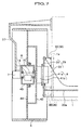
- the vibration generating device 6, the vibrating motor 7 and the roll-drivingmotor 8 are positioned, from the body 1, in the order of the vibrating motor 7, the roll-driving motor 8 and the vibration generating device 6.
- the vibrating motor 7 is positioned close to the body 1 and the vibration generating device 6 is positioned close to the roll 5 (at an outer side of the roll 5).
- a disk-shaped first and second end plates 9 and 10 are separately fixed to the inner periphery of the roll 5.
- the vibration generating device 6 is positioned between the first end plate 9 and the second end plate 10 and concentrically with the roll 5.
- a through opening is formed at a center portion of the first end plate 9, and the casing 11 accommodating the vibration generating device 6 is received in the through opening and thereafter fixed at the fringe part of the through opening by bolts 12.
- the vibration generating device 6 according to this preferred embodiment is a one shaft eccentric drive type, viz. a vibration generating shaft 15, which together with an eccentric weight 14 fixed thereto forms the vibration generating device 6, is rotatably supported within the casing 11 through bearings 13 and is concentric with the roll 5.
- the vibratory roller R employs a hollow and non-shaft type motor having a through opening 16 (Fig. 5A), and specifically a multi-process type radial piston motor 17 is used.
- the radial piston motor 17 is a known hydraulic motor, which is thin and is capable of generating a high torque at low speeds, and as shown in Fig. 5A, an output portion 20 is rotatably supported within a stationary portion 18 forming a case through a bearing 19.
- a thin cylinder block 21 with a circular section is fixed to the output portion 20.
- a cam surface 25 is formed on the inner surface of the stationary portion 18, where the rollers 23 contact.
- a reference numeral 26 in Fig. 5A indicates a disc brake.
- the multi-process type radial piston motor 17 is constructed as above, and the output portion 20 can be formed as a non-shaft configuration. Therefore, since the output portion 20, viewing sectionally from the front side, can be formed as a ring shaped member, the through opening 16 can be provided at the center of the output portion 20.
- the empty core of the through opening 16 is positioned concentrically with the rotary shaft core of the roll 5, and the output portion 20 is fixed to the casing 11 of the vibration generating device by bolts 27.
- One end of the vibration generating shaft 15 of the vibration generating device 6 projects from the casing 11 and is inserted into the through opening 16 of the radial piston motor 17, and it is connected to the output shaft 7b of the vibrating motor 7 through a coupling 28.
- the main feature of the present invention is that the right and left rolls 5 are connected to each other through the roll-driving motors 8 and by a connecting member 29, and that the connecting member 29 is attached to the body 1 through vibration isolating members 30.
- the connecting member 29 according to this preferred embodiment comprises a pair of right and left mounting plates 31 formed by a rectangular-shaped plate member, a pair of right and left brackets 32 bent in a form of the letter L, and a pair of front and rear connecting plates 33 extending in rightward and leftward directions.
- the mounting plate 31 is arranged, at the outer side of the body 1, parallel to the side plate 1a of the body 1.
- the bracket 32 is fixed for example by welding so that one surface of the bracket 32 is apart from and parallel to the mounting plate 31.
- the front and rear connecting plates 33 are fixed perpendicularly at one end to the mounting plate 31 for example by welding in such a way that the bracket 32 is sandwiched between the pair of connecting plates 33.
- Both side plates 1a of the body 1 form a cutting 1b for the insertion of the connecting plates 33, and the pair of connecting plates 33 extends in rightward and leftward directions through the cuttings 1b and within the body 1.
- a reinforcement plate 33a is fixed to the front and rear connecting plates 33 so as to bridge between the connecting plates 33.
- an opening 31a is formed at a center of the mounting plate 31 for the insertion of the radial piston motor 17.
- the radial piston motor 17 is inserted into the opening 31a and the stationary portion 18 thereof is fixed to the mounting plate 31 by bolts 34.
- an opening 32a is formed in the bracket 32, and the output shaft 7a of the vibrating motor 7 is inserted through the opening 32a and into the through opening 16 of the radial piston motor 17.
- the output shaft 7a of the vibrating motor 7 is connected to the vibration generating shaft 15 by the coupling 28.
- the casing of the vibrating motor 7 is fixed to the bracket 32 by bolts 35.
- the right and left rolls 5 accommodating the vibration generating device 6 are connected to each other through the roll-driving motors 8 and by the connecting member 29.
- the connecting member 29 is not limited to a particular shape or the like.
- the connecting member 29 is attached to the body 1 through vibration isolating members 30.
- four corner portions of the mounting plate 31 are attached to the side plate 1a of the body 1 through cylinder-shaped rubber vibration isolators 36.
- Each of the rubber vibration isolators 36 is fixed to the mounting plate 31 and the side plate 1a by bolts or the like.
- the rocking vibration such as shown in Fig. 9, hardly occurs even when the right and left rolls 5 vibrates simultaneously. Therefore, a great vibrating force due to the rocking vibration is not transmitted to the body 1, and a relatively small vibration that is as small as the compaction by the conventional tandem-type vibratory roller is transmitted to the operator seated on the driver's seat C. Also, it is possible to finish the road surface smoothly.
- the present invention it is possible to compact the road surface while both right and left rolls 5 vibrating, and when the rear roll 2 additionally vibrates, the entire and wide range compacting operation of the road surface, which has been carried out by the conventional tandem-type vibratory roller, can be made in addition to the compacting operation at a joint.
- the vibration isolating members 30 (viz. rubber vibration isolators 36) are non-rotatably fixed to the body 1, it is possible to eliminate the drawbacks of the prior art that the deflection side of the rubber vibration isolator varies because the isolator rotates together with the roll, and that suspended load becomes alternate load. As a result, the strength required for the vibration isolating members 30 is decreased, and otherwise the service life of the vibration isolating members 30 is extended.
- the ON-OFF operation of the right and left rolls 5 and the roll 2 is carried out by the switch (not shown), such as a rotary switch capable of switching to the respective vibration modes, provided around the driver's seat C.
- the vibration modes include: (1) a mode only vibrating the right roll 5; and (2) a mode only vibrating the left roll 5; for the local compacting operation, such as a joint, and (3) a mode vibrating all the rolls including the right and left rolls 5 and the rear roll 2; for the entire and wide range compacting operation of the road surface.
- Further vibration modes, such as a mode only vibrating the right and left rolls 5 and a mode only vibrating the rear roll 2 may be adapted when necessary.
- a first modified embodiment of the present invention comprises vibration isolating members 30 (or rubber vibration isolators 36) positioned inside of the body 1.
- the shape of the connecting member 29 is slightly modified.
- Such an arrangement is adaptable to the vibratory roller when there is a sufficient inner space within the body 1.
- the engine for driving the vehicle, hydraulic piping and other parts are compactly positioned within the body 1. Therefore, if the vibration isolating members 30 are positioned inside of the body 1, the shape and the layout design of the mounting devices, such as the vibration isolating member 30 per se and the engine, would suffer from great limitations.
- Providing the vibration isolating members 30 outside of the body 1 can eliminate this problem, and the existing types of vibratory rollers can be readily adapted to the vibratory roller according the present invention.
- the connecting member 29 positions at a lower of the body 1 and extends through the body 1. However, if hydraulic piping or other parts occupies this space, the connecting member 29 may extend below the body 1 without passing through the body 1.
- the vibratory roller R employs a constitution such that the roll-driving motor 8 is a hollow construction-type motor with a through opening 16, and the roll-driving motor 8 is positioned between the vibratingmotor 7 adjacent to the body 1 and the vibration generating device 6 adjacent to the roll 5, and that the driving member for driving the vibration generating device 6 (for example, the vibration generating shaft 15 per se, the coupling 28, and the output shaft 7a of the vibrating motor 7) is inserted through the through opening 16 and is connected to the vibrating motor 7 (hereinafter referred to as "constitution A").
- substitution A the following effects can be achieved.
- the vibrating motor 7 positions at the outer end of the roll 5.
- the output portion 41b of the roll-driving motor 8 is mounted through the bracket 42 to the end plate 44, which is fixed along the inner periphery of the roll 5.
- the stationary portion 41a is mounted to the connecting member 29 made by the mounting plate 31 and the connecting plate 33.
- the connecting member 29 is connected at the mounting plate 31 to the side plate 1a of the body 1 through the rubber vibration isolators 36.
- the casing 45 accommodating the vibration generating device 6 is attached to the end plate 44, and the vibration generating shaft 15 is connected to the vibrating motor 7.
- the vibrating motor 7 positions within the body 1, and only the vibration generating device 6 and the roll-driving motor 8 are arranged within the roll 5.
- the occupying space of the vibration generating device 6 (viz. the casing 11 of the vibration generating device and the like) may be increased in the lateral direction of the roll 5. Therefore, a large-sized vibration generating device can be used, and the vibration generating device may be two shaft-type with gear transmission. Accordingly, a wide range design of the vibration generating device 6 is available in the limited inner space of the roll 5, and various vibration generating devices may be designed for various demands.
- the radial piston motor 17 is thin and is capable of generating a high torque at low speeds. Because the motor 17 generates a high torque at low speeds , reduction gears are not required when applying the motor 17 to the roll 5, and therefore the occupying space of the roll-driving motor 8 may be reduced in the lateral direction of the roll 5. In the combination of the arrangement where the vibrating motor 7 is positioned within the body 1, such a constitution allows more extended occupying space of the vibration generating device 6 in the lateral direction of the roll 5 and more layout designs of the vibration generating device 6 in the end.
Landscapes
- Engineering & Computer Science (AREA)
- Architecture (AREA)
- Civil Engineering (AREA)
- Structural Engineering (AREA)
- Road Paving Machines (AREA)
- Crushing And Grinding (AREA)
Abstract
Description
Claims (4)
- A vibratory roller comprising:a pair of rolls axially supported at both sides of a body in a cantilevered fashion;a pair of vibration generating devices for vibrating each of said rolls;a pair of vibrating motors for driving each of said vibration generating devices; anda pair of roll-driving motors for rotating each of said rolls, wherein said rolls are connected to each other through the roll-driving motors and by a connecting member, and said connecting member is attached to the body through vibration isolating members.
- A vibratory roller according to claim 1, wherein said vibration isolating members are arranged outside of the body.
- A vibratory roller according to claim 1, wherein each of said roll-driving motors is a hollow construction-type motor with a through opening, and said roll-driving motor is positioned between the vibrating motor adjacent to the body and the vibration generating device adjacent to the roll, and wherein a driving member for driving said vibration generating device is inserted through the through opening and is connected to said vibrating motor.
- A vibratory roller according to claim 2, wherein each of said roll-driving motors is a hollow construction-type motor with a through opening, and said roll-driving motor is positioned between the vibrating motor adjacent to the body and the vibration generating device adjacent to the roll, and wherein a driving member for driving said vibration generating device is inserted through the through opening and is connected to said vibrating motor.
Applications Claiming Priority (2)
| Application Number | Priority Date | Filing Date | Title |
|---|---|---|---|
| JP2000164484 | 2000-06-01 | ||
| JP2000164484A JP3728179B2 (en) | 2000-06-01 | 2000-06-01 | Vibration roller |
Publications (3)
| Publication Number | Publication Date |
|---|---|
| EP1160380A2 true EP1160380A2 (en) | 2001-12-05 |
| EP1160380A3 EP1160380A3 (en) | 2002-09-25 |
| EP1160380B1 EP1160380B1 (en) | 2006-07-12 |
Family
ID=18668096
Family Applications (1)
| Application Number | Title | Priority Date | Filing Date |
|---|---|---|---|
| EP01304821A Expired - Lifetime EP1160380B1 (en) | 2000-06-01 | 2001-05-31 | Vitratory roller |
Country Status (5)
| Country | Link |
|---|---|
| US (1) | US6402424B2 (en) |
| EP (1) | EP1160380B1 (en) |
| JP (1) | JP3728179B2 (en) |
| DE (1) | DE60121390T2 (en) |
| NZ (1) | NZ512023A (en) |
Cited By (4)
| Publication number | Priority date | Publication date | Assignee | Title |
|---|---|---|---|---|
| EP1731014A1 (en) * | 2005-06-09 | 2006-12-13 | Martin Brielmaier | Vehicle |
| CN103046455A (en) * | 2012-12-19 | 2013-04-17 | 天津工程机械研究院 | Vibrating steel wheel of vibratory road roller |
| CN111364324A (en) * | 2020-04-16 | 2020-07-03 | 无锡城市职业技术学院 | Novel road roller |
| US11248350B2 (en) | 2017-09-27 | 2022-02-15 | Hamm Ag | Oscillation module |
Families Citing this family (22)
| Publication number | Priority date | Publication date | Assignee | Title |
|---|---|---|---|---|
| US6561729B1 (en) * | 2001-12-14 | 2003-05-13 | Caterpillar Paving Products Inc. | Compacting drum for a work machine |
| US7186056B2 (en) * | 2004-08-13 | 2007-03-06 | Caterpillar Paving Products Inc | Split drum and support arrangement for a compacting work machine |
| US7004275B1 (en) * | 2004-08-13 | 2006-02-28 | Ingersoll-Rand Company | Movable operator station for vehicles |
| JP4880921B2 (en) * | 2005-06-03 | 2012-02-22 | 酒井重工業株式会社 | Rolling roller and road surface rolling method |
| JP4746375B2 (en) | 2005-08-05 | 2011-08-10 | 酒井重工業株式会社 | Compaction vehicle |
| CN101387098B (en) * | 2007-08-09 | 2010-06-09 | 屠卫东 | New road roller exciter apparatus |
| USD589067S1 (en) * | 2007-10-24 | 2009-03-24 | Sakai Heavy Industries, Ltd. | Vibratory roller |
| USD602048S1 (en) * | 2008-10-03 | 2009-10-13 | Caterpillar Paving Products Inc. | Extension plate |
| USD602506S1 (en) * | 2008-10-03 | 2009-10-20 | Caterpillar Paving Products Inc. | Compactor |
| DE102009055950A1 (en) * | 2009-11-27 | 2011-06-01 | Hamm Ag | Compactor for compacting grounds, has movable drum rotatable around drum axle, where drum part of drum comprises vibration generator that is supported at distance from drum axle in drum |
| US8206061B1 (en) * | 2011-05-26 | 2012-06-26 | Caterpillar Inc. | Eccentric vibratory weight shaft for utility compactor |
| CN102747668B (en) * | 2012-07-09 | 2015-08-12 | 池州腾虎机械科技有限公司 | A kind of vibration wheel of road roller that can be exchanged into circular vibration or vibration or complex vibration |
| CN102995521A (en) * | 2013-01-08 | 2013-03-27 | 长安大学 | Energy-saving type vibration exciter for vibratory roller |
| CN103498404B (en) * | 2013-10-11 | 2015-11-25 | 青岛科技大学 | A kind of novel vibratory roller ungraded amplitude exciting agency |
| DE102015112847A1 (en) * | 2015-08-05 | 2017-02-09 | Hamm Ag | compactor |
| US20160201275A1 (en) * | 2016-03-21 | 2016-07-14 | Caterpillar Paving Products Inc. | Vibratory roller for compactors |
| DE102016109888A1 (en) * | 2016-05-30 | 2017-11-30 | Hamm Ag | Soil compactor and method for operating a soil compactor |
| CN110258262B (en) * | 2019-06-26 | 2022-02-18 | 山推工程机械股份有限公司 | Vibratory roller and vibratory roller control method |
| CN113047148A (en) * | 2021-05-08 | 2021-06-29 | 山西路桥第四工程有限公司 | Pavement joint repairing and compacting equipment |
| US12041886B2 (en) * | 2021-07-16 | 2024-07-23 | Cnh Industrial America Llc | Silage compactor |
| CN114657968B (en) * | 2022-04-08 | 2023-06-09 | 北京城乡建设集团有限责任公司 | Portable flatting mill |
| CN116497666B (en) * | 2023-02-07 | 2025-12-02 | 徐工集团工程机械股份有限公司道路机械分公司 | A vibratory roller with intermediate support and a road roller |
Family Cites Families (8)
| Publication number | Priority date | Publication date | Assignee | Title |
|---|---|---|---|---|
| US2549182A (en) * | 1945-10-15 | 1951-04-17 | Southwest Paving Company | Road roller |
| DE1910407A1 (en) * | 1969-02-28 | 1970-09-10 | Benno Kaltenegger | Road roller with four roller drums |
| DE2803172C2 (en) * | 1978-01-25 | 1983-01-05 | Losenhausen Maschinenbau AG, 4000 Düsseldorf | Vibrating roller with two-part roller drum |
| US4732507A (en) * | 1987-03-03 | 1988-03-22 | M-B-W, Inc. | Walk behind soil compactor having a double vibratory drum and an articulated frame |
| US4927289A (en) * | 1988-06-24 | 1990-05-22 | M-B-W Inc. | Vibratory mechanism for a compaction roller |
| DE3906392A1 (en) * | 1989-03-01 | 1990-09-20 | Bomag Gmbh | VIBRATION ROLLER FOR GROUND COMPACTION |
| FR2675204B1 (en) * | 1991-04-15 | 1993-08-06 | Poclain Hydraulics Sa | HYDRAULIC MOTOR AND BRAKE ASSEMBLY AND COMPACTOR USING THE SAME. |
| JP3146411B2 (en) * | 1996-12-12 | 2001-03-19 | 酒井重工業株式会社 | Vibration mechanism and vibration roller using the vibration mechanism |
-
2000
- 2000-06-01 JP JP2000164484A patent/JP3728179B2/en not_active Expired - Lifetime
-
2001
- 2001-05-29 NZ NZ512023A patent/NZ512023A/en not_active IP Right Cessation
- 2001-05-31 DE DE60121390T patent/DE60121390T2/en not_active Expired - Lifetime
- 2001-05-31 EP EP01304821A patent/EP1160380B1/en not_active Expired - Lifetime
- 2001-06-01 US US09/870,697 patent/US6402424B2/en not_active Expired - Lifetime
Cited By (7)
| Publication number | Priority date | Publication date | Assignee | Title |
|---|---|---|---|---|
| EP1731014A1 (en) * | 2005-06-09 | 2006-12-13 | Martin Brielmaier | Vehicle |
| CN103046455A (en) * | 2012-12-19 | 2013-04-17 | 天津工程机械研究院 | Vibrating steel wheel of vibratory road roller |
| CN103046455B (en) * | 2012-12-19 | 2015-11-18 | 天津工程机械研究院 | A kind of vibratory roller vibration steel wheel |
| US11248350B2 (en) | 2017-09-27 | 2022-02-15 | Hamm Ag | Oscillation module |
| US11913178B2 (en) | 2017-09-27 | 2024-02-27 | Hamm Ag | Oscillation module |
| CN111364324A (en) * | 2020-04-16 | 2020-07-03 | 无锡城市职业技术学院 | Novel road roller |
| CN111364324B (en) * | 2020-04-16 | 2024-04-12 | 无锡城市职业技术学院 | Road roller |
Also Published As
| Publication number | Publication date |
|---|---|
| US6402424B2 (en) | 2002-06-11 |
| JP3728179B2 (en) | 2005-12-21 |
| US20010048221A1 (en) | 2001-12-06 |
| NZ512023A (en) | 2002-11-26 |
| EP1160380B1 (en) | 2006-07-12 |
| EP1160380A3 (en) | 2002-09-25 |
| DE60121390D1 (en) | 2006-08-24 |
| JP2001342609A (en) | 2001-12-14 |
| DE60121390T2 (en) | 2007-07-19 |
Similar Documents
| Publication | Publication Date | Title |
|---|---|---|
| US6402424B2 (en) | Vibratory roller | |
| CN1734019B (en) | Split drum and support arrangement for a compacting work machine | |
| US8376655B2 (en) | Compactor with smooth hose routing | |
| KR100322504B1 (en) | As a vibrating tire | |
| US7857544B2 (en) | Extension plate for a compactor | |
| JPH07137984A (en) | Mobile crane | |
| CN104894951A (en) | Double vibrating mechanism with motor, ironing plate and paver | |
| JP2003096713A (en) | Vibration roller | |
| JP4880921B2 (en) | Rolling roller and road surface rolling method | |
| JP4109700B2 (en) | Vibration tire roller | |
| JP4203203B2 (en) | Rolling roller | |
| US20030118401A1 (en) | Suspension arrangement for a compacting work machine | |
| JP3895979B2 (en) | Vibration tire roller | |
| JP2001140211A (en) | Hand guide roller | |
| JP2908310B2 (en) | Driving device for rolling machine having tire rolling wheel and tire roller | |
| JP4214184B2 (en) | Idler support structure | |
| JP3431292B2 (en) | Working part structure of work vehicle | |
| JP3789942B2 (en) | Tire structure | |
| JP2003268808A (en) | Slewing type working machine | |
| JP2008106514A (en) | Road paving machine with function of coping with different pavement thickness | |
| JPH0647975Y2 (en) | Backhoe rotary joint mounting structure | |
| JPH1161726A (en) | Rolling machine | |
| JPH1059229A (en) | Slewing working vehicle | |
| JP2004346549A (en) | Vibration roll support structure | |
| JP2908265B2 (en) | Concrete pavement finishing device and its vibration compaction machine and vibration unit |
Legal Events
| Date | Code | Title | Description |
|---|---|---|---|
| PUAI | Public reference made under article 153(3) epc to a published international application that has entered the european phase |
Free format text: ORIGINAL CODE: 0009012 |
|
| AK | Designated contracting states |
Kind code of ref document: A2 Designated state(s): AT BE CH CY DE DK ES FI FR GB GR IE IT LI LU MC NL PT SE TR |
|
| AX | Request for extension of the european patent |
Free format text: AL;LT;LV;MK;RO;SI |
|
| PUAL | Search report despatched |
Free format text: ORIGINAL CODE: 0009013 |
|
| AK | Designated contracting states |
Kind code of ref document: A3 Designated state(s): AT BE CH CY DE DK ES FI FR GB GR IE IT LI LU MC NL PT SE TR |
|
| AX | Request for extension of the european patent |
Free format text: AL;LT;LV;MK;RO;SI |
|
| RIC1 | Information provided on ipc code assigned before grant |
Free format text: 7E 01C 19/28 A, 7E 02D 3/074 B, 7E 02D 3/026 B |
|
| 17P | Request for examination filed |
Effective date: 20021031 |
|
| 17Q | First examination report despatched |
Effective date: 20030116 |
|
| AKX | Designation fees paid |
Designated state(s): DE FR GB IT SE |
|
| GRAP | Despatch of communication of intention to grant a patent |
Free format text: ORIGINAL CODE: EPIDOSNIGR1 |
|
| GRAC | Information related to communication of intention to grant a patent modified |
Free format text: ORIGINAL CODE: EPIDOSCIGR1 |
|
| GRAS | Grant fee paid |
Free format text: ORIGINAL CODE: EPIDOSNIGR3 |
|
| GRAA | (expected) grant |
Free format text: ORIGINAL CODE: 0009210 |
|
| AK | Designated contracting states |
Kind code of ref document: B1 Designated state(s): DE FR GB IT SE |
|
| PG25 | Lapsed in a contracting state [announced via postgrant information from national office to epo] |
Ref country code: IT Free format text: LAPSE BECAUSE OF FAILURE TO SUBMIT A TRANSLATION OF THE DESCRIPTION OR TO PAY THE FEE WITHIN THE PRESCRIBED TIME-LIMIT;WARNING: LAPSES OF ITALIAN PATENTS WITH EFFECTIVE DATE BEFORE 2007 MAY HAVE OCCURRED AT ANY TIME BEFORE 2007. THE CORRECT EFFECTIVE DATE MAY BE DIFFERENT FROM THE ONE RECORDED. Effective date: 20060712 |
|
| REG | Reference to a national code |
Ref country code: GB Ref legal event code: FG4D |
|
| REF | Corresponds to: |
Ref document number: 60121390 Country of ref document: DE Date of ref document: 20060824 Kind code of ref document: P |
|
| REG | Reference to a national code |
Ref country code: SE Ref legal event code: TRGR |
|
| EN | Fr: translation not filed | ||
| PLBE | No opposition filed within time limit |
Free format text: ORIGINAL CODE: 0009261 |
|
| STAA | Information on the status of an ep patent application or granted ep patent |
Free format text: STATUS: NO OPPOSITION FILED WITHIN TIME LIMIT |
|
| 26N | No opposition filed |
Effective date: 20070413 |
|
| GBPC | Gb: european patent ceased through non-payment of renewal fee |
Effective date: 20070531 |
|
| PG25 | Lapsed in a contracting state [announced via postgrant information from national office to epo] |
Ref country code: FR Free format text: LAPSE BECAUSE OF FAILURE TO SUBMIT A TRANSLATION OF THE DESCRIPTION OR TO PAY THE FEE WITHIN THE PRESCRIBED TIME-LIMIT Effective date: 20070511 |
|
| PG25 | Lapsed in a contracting state [announced via postgrant information from national office to epo] |
Ref country code: GB Free format text: LAPSE BECAUSE OF NON-PAYMENT OF DUE FEES Effective date: 20070531 |
|
| PG25 | Lapsed in a contracting state [announced via postgrant information from national office to epo] |
Ref country code: FR Free format text: LAPSE BECAUSE OF FAILURE TO SUBMIT A TRANSLATION OF THE DESCRIPTION OR TO PAY THE FEE WITHIN THE PRESCRIBED TIME-LIMIT Effective date: 20060712 |
|
| PGFP | Annual fee paid to national office [announced via postgrant information from national office to epo] |
Ref country code: DE Payment date: 20200519 Year of fee payment: 20 |
|
| PGFP | Annual fee paid to national office [announced via postgrant information from national office to epo] |
Ref country code: SE Payment date: 20200512 Year of fee payment: 20 |
|
| REG | Reference to a national code |
Ref country code: DE Ref legal event code: R071 Ref document number: 60121390 Country of ref document: DE |
|
| REG | Reference to a national code |
Ref country code: SE Ref legal event code: EUG |