EP1162357A2 - Verfahren und Vorrichtung zum Überwachen des Betriebs eines Verbrennungsmotors - Google Patents
Verfahren und Vorrichtung zum Überwachen des Betriebs eines Verbrennungsmotors Download PDFInfo
- Publication number
- EP1162357A2 EP1162357A2 EP01112926A EP01112926A EP1162357A2 EP 1162357 A2 EP1162357 A2 EP 1162357A2 EP 01112926 A EP01112926 A EP 01112926A EP 01112926 A EP01112926 A EP 01112926A EP 1162357 A2 EP1162357 A2 EP 1162357A2
- Authority
- EP
- European Patent Office
- Prior art keywords
- pressure
- combustion chamber
- internal combustion
- combustion engine
- sensor means
- Prior art date
- Legal status (The legal status is an assumption and is not a legal conclusion. Google has not performed a legal analysis and makes no representation as to the accuracy of the status listed.)
- Granted
Links
- 238000000034 method Methods 0.000 title claims description 12
- 238000012544 monitoring process Methods 0.000 title claims description 9
- 238000002485 combustion reaction Methods 0.000 claims abstract description 106
- 230000006978 adaptation Effects 0.000 claims 1
- 239000000567 combustion gas Substances 0.000 abstract 1
- 239000007789 gas Substances 0.000 abstract 1
- 238000002347 injection Methods 0.000 description 6
- 239000007924 injection Substances 0.000 description 6
- 238000011156 evaluation Methods 0.000 description 3
- 230000001419 dependent effect Effects 0.000 description 2
- 239000000446 fuel Substances 0.000 description 2
- 239000012528 membrane Substances 0.000 description 2
- 239000000203 mixture Substances 0.000 description 2
- 238000012360 testing method Methods 0.000 description 2
- 238000005452 bending Methods 0.000 description 1
- 230000003111 delayed effect Effects 0.000 description 1
- 238000009795 derivation Methods 0.000 description 1
- 238000011835 investigation Methods 0.000 description 1
Images

Classifications
-
- F—MECHANICAL ENGINEERING; LIGHTING; HEATING; WEAPONS; BLASTING
- F02—COMBUSTION ENGINES; HOT-GAS OR COMBUSTION-PRODUCT ENGINE PLANTS
- F02D—CONTROLLING COMBUSTION ENGINES
- F02D41/00—Electrical control of supply of combustible mixture or its constituents
- F02D41/02—Circuit arrangements for generating control signals
- F02D41/14—Introducing closed-loop corrections
- F02D41/1438—Introducing closed-loop corrections using means for determining characteristics of the combustion gases; Sensors therefor
- F02D41/1444—Introducing closed-loop corrections using means for determining characteristics of the combustion gases; Sensors therefor characterised by the characteristics of the combustion gases
- F02D41/1448—Introducing closed-loop corrections using means for determining characteristics of the combustion gases; Sensors therefor characterised by the characteristics of the combustion gases the characteristics being an exhaust gas pressure
- F02D41/145—Introducing closed-loop corrections using means for determining characteristics of the combustion gases; Sensors therefor characterised by the characteristics of the combustion gases the characteristics being an exhaust gas pressure with determination means using an estimation
-
- F—MECHANICAL ENGINEERING; LIGHTING; HEATING; WEAPONS; BLASTING
- F02—COMBUSTION ENGINES; HOT-GAS OR COMBUSTION-PRODUCT ENGINE PLANTS
- F02D—CONTROLLING COMBUSTION ENGINES
- F02D35/00—Controlling engines, dependent on conditions exterior or interior to engines, not otherwise provided for
- F02D35/02—Controlling engines, dependent on conditions exterior or interior to engines, not otherwise provided for on interior conditions
- F02D35/023—Controlling engines, dependent on conditions exterior or interior to engines, not otherwise provided for on interior conditions by determining the cylinder pressure
-
- F—MECHANICAL ENGINEERING; LIGHTING; HEATING; WEAPONS; BLASTING
- F02—COMBUSTION ENGINES; HOT-GAS OR COMBUSTION-PRODUCT ENGINE PLANTS
- F02D—CONTROLLING COMBUSTION ENGINES
- F02D41/00—Electrical control of supply of combustible mixture or its constituents
- F02D41/0002—Controlling intake air
- F02D41/0007—Controlling intake air for control of turbo-charged or super-charged engines
-
- F—MECHANICAL ENGINEERING; LIGHTING; HEATING; WEAPONS; BLASTING
- F02—COMBUSTION ENGINES; HOT-GAS OR COMBUSTION-PRODUCT ENGINE PLANTS
- F02D—CONTROLLING COMBUSTION ENGINES
- F02D2200/00—Input parameters for engine control
- F02D2200/02—Input parameters for engine control the parameters being related to the engine
- F02D2200/04—Engine intake system parameters
- F02D2200/0406—Intake manifold pressure
- F02D2200/0408—Estimation of intake manifold pressure
-
- Y—GENERAL TAGGING OF NEW TECHNOLOGICAL DEVELOPMENTS; GENERAL TAGGING OF CROSS-SECTIONAL TECHNOLOGIES SPANNING OVER SEVERAL SECTIONS OF THE IPC; TECHNICAL SUBJECTS COVERED BY FORMER USPC CROSS-REFERENCE ART COLLECTIONS [XRACs] AND DIGESTS
- Y02—TECHNOLOGIES OR APPLICATIONS FOR MITIGATION OR ADAPTATION AGAINST CLIMATE CHANGE
- Y02T—CLIMATE CHANGE MITIGATION TECHNOLOGIES RELATED TO TRANSPORTATION
- Y02T10/00—Road transport of goods or passengers
- Y02T10/10—Internal combustion engine [ICE] based vehicles
- Y02T10/12—Improving ICE efficiencies
Definitions
- the present invention relates to a method according to the preamble of claim 1 for monitoring the operation of an internal combustion engine, in particular one Diesel engine, and a correspondingly designed device according to the preamble of claim 7.
- combustion chamber Cylinder
- Combustion chamber or cylinder pressure of particular importance, because of Evaluation of the combustion chamber pressure in the respective combustion chamber Combustion process can be monitored.
- DE 197 49 814 A1 describes a method for detecting the Combustion chamber pressure curve as a function of the crankshaft angle at one Internal combustion engine described, being in each cylinder of the internal combustion engine Pressure sensor for detecting the respective combustion chamber pressure is used, the Output signal for the determination of variables that the combustion process in the describe the respective cylinder or combustion chamber, can be evaluated.
- the so-called Determine differential pressure integral For this purpose, the difference between the im fired operation, i.e. in combustion mode, measured combustion chamber pressure and that in towed operation, i.e. without combustion, occurring combustion chamber pressure determined and this difference integrated.
- the resulting one Differential pressure integral represents an essential variable, because based on the size of the Differential pressure integrals can be assessed, how the combustion took place and whether there has been a burn at all or possibly a Misfiring has occurred.
- Exhaust gas back pressure sensor makes sense, which the immediately before the pressure prevailing in the turbine is detected in order to draw conclusions about the exhaust gas recirculation enable.
- Such an exhaust gas back pressure sensor can be adjusted the gas dynamics, the boost pressure, the exhaust gas recirculation control and the control of the Combustion process in the individual combustion chambers of the internal combustion engine bring enormous advantage.
- Exhaust gas back pressure sensors have the disadvantage, however, that their behavior becomes even more pronounced due to combustion taking place in a combustion chamber changed, the closer they are to the corresponding combustion chamber.
- the present invention has for its object a method and a Propose a device for monitoring the operation of an internal combustion engine, with a reliable statement about the operating state of the internal combustion engine with less effort and thus also with lower costs can.
- Combustion chamber pressure occurring is recorded and evaluated.
- Extensive investigations have shown that there is a correlation between the combustion chamber pressure thus recorded and the boost pressure or exhaust gas back pressure of the internal combustion engine.
- An evaluation of the gas exchange area can thus be based on the Combustion chamber pressure signal to be concluded on the boost pressure or exhaust gas back pressure.
- a reliable correlation between the combustion chamber pressure and the boost pressure or to get exhaust back pressure it is recommended to use several Charge change cycles, especially over at least 40 charge change cycles average. From the pressure signal thus averaged, a statement about the Boost pressure or exhaust back pressure are derived.
- the present invention is particularly useful for monitoring the operation of a Diesel engine.
- the invention can also be applied to other types of engine, such as on petrol engines.
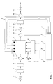
- FIG. 1 shows a diesel engine 1 with four combustion chambers or cylinders 2.
- the diesel engine 1 is connected via an air mass meter 6, a compressor (compressor) 7, a charge air cooler 8 and an intake manifold 9 fed the charge air.
- About one Injection system 4 becomes the start of injection or the start of delivery and the delivery rate a corresponding fuel mixture for the individual cylinders 2 of the diesel engine 1 controlled. That as a result of the combustion processes in the individual cylinders 2
- Exhaust gas that occurs is collected by an exhaust manifold 10 and a turbine 12 supplied, which is connected to the compressor 7 via a turbocharger shaft 16.
- an adjustable vane of turbine 12 is also shown separately.
- the turbine 12 is followed by an exhaust system 13 which outputs the exhaust gas via an outlet pipe 14.
- the exhaust gas collected by the exhaust manifold 10 is via a return path returned to the inlet header 9. There is a valve in this exhaust gas recirculation path 15 arranged, by means of which the exhaust gas recirculation can be controlled.
- a pressure sensor 3 is arranged in each cylinder 2 of the diesel engine 1.
- Everyone Pressure sensor 3 has, for example, a flexible membrane, which depends on the in the cylinder pressure prevailing in the respective cylinder is bent. Of each Pressure sensor 3 thus becomes dependent on the bending of the corresponding one Pressure membrane, i.e. depending on the prevailing in the respective cylinder Cylinder pressure, generates a corresponding cylinder pressure signal a, which one Engine control unit 5 is supplied.
- the engine control unit 5 evaluates the individual cylinder pressure signals a by depending on the combustion process in the corresponding cylinders 2.
- the evaluation of the cylinder pressure signals a can in particular be dependent on the crankshaft angle respectively.
- a (not shown in Fig. 1) Crankshaft sensor provided, one for the current position of the crankshaft representative output signal generated and also supplied to the engine control unit 5. This can be done by evaluating the cylinder pressure signals in this way Engine control unit 5 to the combustion state prevailing in each cylinder 2 close and the combustion processes taking place in the individual cylinders 2 control accordingly.
- the engine control unit 5 generates after evaluating the Cylinder pressure signals a control signals b, c, thus the injection quantity and the start of injection or the injection duration of the fuel mixture for the individual cylinders 2 to be determined.
- the engine control unit 5 evaluates the individual cylinder pressure signals a also from to the boost pressure and the exhaust gas back pressure of the diesel engine 1 conclude. To make a reliable statement about the boost pressure and the To achieve exhaust gas back pressure, this must take place over several gas exchange cycles be averaged. In practice it has turned out to be sufficient if over at least 40 charge exchange cycles are averaged.
- 2A is the boost pressure derived from the averaged cylinder pressure signals a plotted against the boost pressure actually measured in the engine test bench. 2A also shows that there is an approximately linear relationship, so that concludes from the averaged cylinder pressure signals a the boost pressure can be.
- FIG. 2B is that derived from the averaged cylinder pressure signals a Exhaust gas back pressure compared to that actually measured on the engine test bench Exhaust gas back pressure applied.
- Fig. 2B can be seen that also for the Exhaust gas back pressure has an almost linear relationship, so that by Application of a corresponding linear model from the averaged Cylinder pressure signals a can be concluded indirectly on the exhaust gas back pressure.
- control signals d and e for controlling the exhaust gas recirculation mass flow correlating with the exhaust gas back pressure generated in the return path or the boost pressure.
- the control signal d is supplied to the valve 15 located in the exhaust gas recirculation path to act on it Way the exhaust gas recirculation mass flow, i.e. to control the exhaust gas recirculation.
- the control signal e is the adjustable guide vane 11 supplied to the turbine, by adjusting the Boost pressure can be influenced accordingly.
Landscapes
- Engineering & Computer Science (AREA)
- Chemical & Material Sciences (AREA)
- Combustion & Propulsion (AREA)
- Mechanical Engineering (AREA)
- General Engineering & Computer Science (AREA)
- Combined Controls Of Internal Combustion Engines (AREA)
Abstract
Description
- 1
- Verbrennungsmotor
- 2
- Zylinder
- 3
- Zylinderdrucksensor
- 4
- Einspritzsystem
- 5
- Motorsteuergerät
- 6
- Luftmassenmesser
- 7
- Verdichter
- 8
- Ladeluftkühler
- 9
- Einlassammler
- 10
- Abgassammler
- 11
- Leitschaufel der Turbine
- 12
- Turbine
- 13
- Abgasanlage
- 14
- Auslassrohr
- 15
- Stellventil
- 16
- Turboladerwelle
- a
- Zylinderdrucksignal
- b-e
- Stellsignal
Claims (10)
- Verfahren zum Überwachen des Betriebs eines Verbrennungsmotors,wobei der in mindestens einem Brennraum (2) des Verbrennungsmotors (1) auftretende Brennraumdruck mit Drucksensormitteln (3) erfasst wird, undwobei das von den Drucksensormitteln (3) erzeugte Brennraumdrucksignal (a) ausgewertet wird, um eine Aussage über den Betrieb des Verbrennungsmotors (1) zu gewinnen, dadurch gekennzeichnet, daß aus dem Brennraumdrucksignal (a) der Drucksensormittel (3) eine Aussage über den Ladedruck des Verbrennungsmotors (1) abgeleitet und zur Steuerung des Betriebs des Verbrennungsmotors (1) verwendet wird.
- Verfahren zum Überwachen des Betriebs eines Verbrennungsmotors, wobei der in mindestens einem Brennraum (2) des Verbrennungsmotors (1) auftretende Brennraumdruck mit Drucksensormitteln (3) erfasst wird, und wobei das von den Drucksensormitteln (3) erzeugte Brennraumdrucksignal (a) ausgewertet wird, um eine Aussage über den Betrieb des Verbrennungsmotors (1) zu gewinnen, dadurch gekennzeichnet, daß aus dem Brennraumdrucksignal (a) der Drucksensormittel (3) eine Aussage über den Abgasgegendruck abgeleitet und zur Steuerung des Betriebs des Verbrennungsmotors (1) verwendet wird.
- Verfahren nach Anspruch 1 oder 2, dadurch gekennzeichnet, daß das Brennraumdrucksignal (a) der Drucksensormittel (3) über mehrere Ladungswechselzyklen des Verbrennungsmotors (1) gemittelt und aus dem somit gewonnenen gemittelten Brennraumdrucksignal die Aussage über den Ladedruck bzw. den Abgasgegendruck des Verbrennungsmotors (1) abgeleitet wird.
- Verfahren nach Anspruch 3, dadurch gekennzeichnet, daß das Brennraumdrucksignal (a) der Drucksensormittel (3) über mindestens 40 Ladungswechselzyklen gemittelt wird.
- Verfahren nach einem der vorhergehenden Ansprüche, dadurch gekennzeichnet, daß die Aussage über den Ladedruck bzw. Abgasgegendruck des Verbrennungsmotors (1) durch Anwendung eines linearen Modells aus dem Brennraumdrucksignal (a) der Drucksensormittel (3) abgeleitet wird.
- Verfahren nach einem der vorhergehenden Ansprüche, dadurch gekennzeichnet, daß der Verbrennungsmotor (1) mehrere Brennräume (2) aufweist, wobei für jeden Brennraum (2) Drucksensormittel (3) zum Erfassen des in dem jeweiligen Brennraum (2) auftretenden Brennraumdrucks vorgesehen sind, und wobei die von den einzelnen Drucksensormitteln (3) erzeugten Brennraumdrucksignale (a) in Kombination ausgewertet werden, um die Aussage über den Ladedruck bzw. Abgasgegendruck des Verbrennungsmotors (1) zu gewinnen.
- Vorrichtung zum Überwachen des Betriebs eines Verbrennungsmotors, mit Drucksensormitteln (3) zum Erfassen des in mindestens einem Brennraum (2) des Verbrennungsmotors (1) auftretenden Brennraumdrucks, und mit Steuermitteln (5) zum Auswerten des von den Drucksensormitteln (3) erzeugten Brennraumdrucksignals (a), um eine Aussage über den Betrieb des Verbrennungsmotors (1) zu gewinnen, dadurch gekennzeichnet, daß die Steuermittel (5) derart ausgestaltet sind, dass sie aus dem Brennraumdrucksignal (a) der Drucksensormittel (3) eine Aussage über den Ladedruck des Verbrennungsmotors (1) ableiten und davon abhängig Ladedruckanpassungsmittel (11) zur Einstellung des Ladedrucks des Verbrennungsmotors (1) ansteuern.
- Vorrichtung zum Überwachen des Betriebs eines Verbrennungsmotors, mit Drucksensormitteln (3) zum Erfassen des in mindestens einem Brennraum (2) des Verbrennungsmotors (1) auftretenden Brennraumdrucks, und mit Steuermitteln (5) zum Auswerten des von den Drucksensormitteln (3) erzeugten Brennraumdrucksignals, um eine Aussage über den Betrieb des Verbrennungsmotors (1) zu gewinnen, dadurch gekennzeichnet, daß die Steuermittel (5) derart ausgestaltet sind, dass sie aus dem Brennraumdrucksignal (a) der Drucksensormittel (3) eine Aussage über den Abgasgegendruck ableiten und davon abhängig Abgasrückführungs-Anpassungsmittel (15) zur Einstellung der Abgasrückführung des Verbrennungsmotors (1) ansteuern.
- Vorrichtung nach Anspruch 7 oder 8, dadurch gekennzeichnet, daß die Steuermittel zur Durchführung des Verfahrens nach einem der Ansprüche 1-6 ausgestaltet sind.
- Vorrichtung nach einem der Ansprüche 7-9, dadurch gekennzeichnet, daß der insbesondere als Dieselmotor ausgestaltete Verbrennungsmotor (1) mehrere Brennräume (2) aufweist, wobei jedem Brennraum (2) Drucksensormittel (3) zum Erfassen des in dem entsprechenden Brennraum (2) auftretenden Brennraumdrucks zugeordnet sind, und daß die Steuermittel (5) derart ausgestaltet sind, dass sie die von den einzelnen Drucksensormitteln (3) erzeugten Brennraumdrucksignale (a) in Kombination auswerten, um die Aussage über den Ladedruck bzw. Abgasgegendruck zu gewinnen.
Applications Claiming Priority (2)
| Application Number | Priority Date | Filing Date | Title |
|---|---|---|---|
| DE10028886 | 2000-06-10 | ||
| DE10028886A DE10028886A1 (de) | 2000-06-10 | 2000-06-10 | Verfahren und Vorrichtung zum Überwachen des Betriebs eines Verbrennungsmotors |
Publications (3)
| Publication Number | Publication Date |
|---|---|
| EP1162357A2 true EP1162357A2 (de) | 2001-12-12 |
| EP1162357A3 EP1162357A3 (de) | 2002-07-17 |
| EP1162357B1 EP1162357B1 (de) | 2006-11-02 |
Family
ID=7645434
Family Applications (1)
| Application Number | Title | Priority Date | Filing Date |
|---|---|---|---|
| EP01112926A Expired - Lifetime EP1162357B1 (de) | 2000-06-10 | 2001-06-06 | Verfahren und Vorrichtung zum Überwachen des Betriebs eines Verbrennungsmotors |
Country Status (2)
| Country | Link |
|---|---|
| EP (1) | EP1162357B1 (de) |
| DE (2) | DE10028886A1 (de) |
Cited By (7)
| Publication number | Priority date | Publication date | Assignee | Title |
|---|---|---|---|---|
| FR2833998A1 (fr) * | 2001-12-20 | 2003-06-27 | Volkswagen Ag | Procede et dispositif pour determiner le flux massique de recyclage des gaz d'echappement d'un moteur a combustion interne |
| WO2004048761A1 (en) * | 2002-11-27 | 2004-06-10 | Ricardo Uk Limited | Improved engine management |
| FR2871521A1 (fr) * | 2004-06-11 | 2005-12-16 | Peugeot Citroen Automobiles Sa | Systeme d'estimation de la pression dans le collecteur d'echappement d'un moteur diesel et procede de calibrage de ce systeme |
| EP1777397A1 (de) * | 2005-10-24 | 2007-04-25 | Renault s.a.s. | Verfahren und System zum Schätzen des Druckes im Ansaugkrümmer einer Verbrennungskraftmaschine |
| EP1830059A4 (de) * | 2004-10-07 | 2011-10-19 | Toyota Motor Co Ltd | Vorrichtung und verfahren zur steuerung eines verbrennungsmotors |
| EP2754875A1 (de) * | 2013-01-15 | 2014-07-16 | Robert Bosch Gmbh | Verfahren zum Betreiben einer Brennkraftmaschine |
| EP2910755A1 (de) | 2014-02-20 | 2015-08-26 | GE Jenbacher GmbH & Co OG | Verfahren zum Betreiben einer Brennkraftmaschine |
Families Citing this family (4)
| Publication number | Priority date | Publication date | Assignee | Title |
|---|---|---|---|---|
| DE102006016905A1 (de) * | 2006-04-11 | 2007-10-25 | Daimlerchrysler Ag | Verfahren zum Betreiben einer Brennkraftmaschine |
| DE102009000149A1 (de) | 2009-01-12 | 2010-07-15 | Robert Bosch Gmbh | Verfahren zum Betreiben einer Brennkraftmaschine und Steuergerät zum Steuern und/oder Regeln einer Brennkraftmaschine |
| DE102015219133A1 (de) | 2015-10-02 | 2017-04-06 | Continental Automotive Gmbh | Verfahren zum Betreiben einer Brennkraftmaschine für ein Kraftfahrzeug und System für eine Brennkraftmaschine |
| DE102019213092A1 (de) | 2019-08-30 | 2021-03-04 | Volkswagen Aktiengesellschaft | Verfahren zur Diagnostik von Verbrennungsaussetzern einer Verbrennungskraftmaschine |
Family Cites Families (11)
| Publication number | Priority date | Publication date | Assignee | Title |
|---|---|---|---|---|
| US3930221A (en) * | 1973-03-09 | 1975-12-30 | Frank Thing | Exhaust backpressure warning system |
| JPS58217723A (ja) * | 1982-06-09 | 1983-12-17 | Fuji Heavy Ind Ltd | 過給機付エンジンの過給圧制御装置 |
| JPH03233162A (ja) * | 1990-02-06 | 1991-10-17 | Mitsubishi Electric Corp | 内燃機関の燃焼制御装置 |
| JP2668037B2 (ja) * | 1991-12-27 | 1997-10-27 | 三菱自動車工業株式会社 | 自動車用エンジン |
| DE4214648A1 (de) * | 1992-05-02 | 1993-11-04 | Bosch Gmbh Robert | System zur steuerung einer brennkraftmaschine |
| DE4326949C2 (de) * | 1993-08-11 | 1997-08-07 | Opel Adam Ag | Managementsystem für Kolbenbrennkraftmaschinen, insbesondere Ottomotoren von Kraftfahrzeugen |
| US6167755B1 (en) * | 1993-12-14 | 2001-01-02 | Robert Bosch Gmbh | Device for determining load in an internal combustion engine |
| DE19539919C2 (de) * | 1994-10-26 | 1998-08-13 | Hitachi Ltd | Zylinderinnendruck-Abfühlvorrichtung für Mehrzylindermotoren |
| JP3323974B2 (ja) * | 1995-02-24 | 2002-09-09 | 株式会社ユニシアジェックス | 内燃機関の制御装置 |
| US5794605A (en) * | 1995-03-07 | 1998-08-18 | Sanshin Kogyo Kabushiki Kaisha | Fuel control for marine engine |
| DE10002112C2 (de) * | 2000-01-19 | 2002-04-11 | Bosch Gmbh Robert | Verfahren zur Diagnose eines Kraftstoffversorgungssystems für Brennkraftmaschinen |
-
2000
- 2000-06-10 DE DE10028886A patent/DE10028886A1/de not_active Withdrawn
-
2001
- 2001-06-06 DE DE50111343T patent/DE50111343D1/de not_active Expired - Lifetime
- 2001-06-06 EP EP01112926A patent/EP1162357B1/de not_active Expired - Lifetime
Cited By (12)
| Publication number | Priority date | Publication date | Assignee | Title |
|---|---|---|---|---|
| FR2833998A1 (fr) * | 2001-12-20 | 2003-06-27 | Volkswagen Ag | Procede et dispositif pour determiner le flux massique de recyclage des gaz d'echappement d'un moteur a combustion interne |
| WO2004048761A1 (en) * | 2002-11-27 | 2004-06-10 | Ricardo Uk Limited | Improved engine management |
| FR2871521A1 (fr) * | 2004-06-11 | 2005-12-16 | Peugeot Citroen Automobiles Sa | Systeme d'estimation de la pression dans le collecteur d'echappement d'un moteur diesel et procede de calibrage de ce systeme |
| EP1607605A1 (de) * | 2004-06-11 | 2005-12-21 | Peugeot Citroen Automobiles SA | System zum Abschätzen des Drucks im Abgaskrümmer einer Dieselbrennkraftmaschine und Verfahren zur Systemkalibrierung |
| EP1830059A4 (de) * | 2004-10-07 | 2011-10-19 | Toyota Motor Co Ltd | Vorrichtung und verfahren zur steuerung eines verbrennungsmotors |
| EP1777397A1 (de) * | 2005-10-24 | 2007-04-25 | Renault s.a.s. | Verfahren und System zum Schätzen des Druckes im Ansaugkrümmer einer Verbrennungskraftmaschine |
| FR2892453A1 (fr) * | 2005-10-24 | 2007-04-27 | Renault Sas | Procede et dispositif pour estimer la pression regnant dans le collecteur d'admission d'un moteur a combustion interne |
| EP2754875A1 (de) * | 2013-01-15 | 2014-07-16 | Robert Bosch Gmbh | Verfahren zum Betreiben einer Brennkraftmaschine |
| EP2910755A1 (de) | 2014-02-20 | 2015-08-26 | GE Jenbacher GmbH & Co OG | Verfahren zum Betreiben einer Brennkraftmaschine |
| AT515499A1 (de) * | 2014-02-20 | 2015-09-15 | Ge Jenbacher Gmbh & Co Og | Verfahren zum Betreiben einer Brennkraftmaschine |
| AT515499B1 (de) * | 2014-02-20 | 2016-01-15 | Ge Jenbacher Gmbh & Co Og | Verfahren zum Betreiben einer Brennkraftmaschine |
| US10161320B2 (en) | 2014-02-20 | 2018-12-25 | Ge Jenbacher Gmbh & Co Og | Method of operating an internal combustion engine |
Also Published As
| Publication number | Publication date |
|---|---|
| EP1162357B1 (de) | 2006-11-02 |
| EP1162357A3 (de) | 2002-07-17 |
| DE50111343D1 (de) | 2006-12-14 |
| DE10028886A1 (de) | 2001-12-13 |
Similar Documents
| Publication | Publication Date | Title |
|---|---|---|
| DE102007036258B4 (de) | Verfahren und Vorrichtung zum Betreiben einer Brennkraftmaschine | |
| EP1247016B2 (de) | Verfahren und vorrichtung zur steuerung einer brennkraftmaschine mit einem luftsystem | |
| DE102008027762B3 (de) | Verfahren und Vorrichtung zum Diagnostizieren eines Ansaugtrakts einer Brennkraftmaschine | |
| DE602004001100T2 (de) | Abgasregeleinrichtung einer Brennkraftmaschine und Verfahren zur Schätzung des Abgasdurchflusses | |
| DE102004041767A1 (de) | Verfahren und Vorrichtung zum Betreiben einer Brennkraftmaschine mit Abgasrückführung | |
| EP3527810B1 (de) | Verfahren zum betrieb einer verbrennungskraftmaschine | |
| DE102016219781A1 (de) | Verfahren und Steuergerät zum Abgleich und zur Diagnose eines Abgasrückführmassenstrommessers | |
| DE102008005958A1 (de) | Verfahren und Vorrichtung zur Identifizierung eines fehlerhaften Drucksensors in einem Ansaugtrakt einer Brennkraftmaschine | |
| EP1162357B1 (de) | Verfahren und Vorrichtung zum Überwachen des Betriebs eines Verbrennungsmotors | |
| DE10232337A1 (de) | Verfahren und Vorrichtung zur Überwachung einer Luftmassenmessvorrichtung | |
| WO2016058775A1 (de) | Verfahren zum überwachen des sekundärluftsystems in einer abgasreinigungsanlage einer brennkraftmaschine | |
| DE102005056517A1 (de) | Verfahren zur Bestimmung der Drehzahl eines Verdichters, insbesondere eines Turboladers | |
| DE102006021091B3 (de) | Verfahren und Vorrichtung zur Diagnose der Wirksamkeit eines Abgaskatalysators | |
| DE102004038733A1 (de) | Verfahren und Vorrichtung zum Betreiben einer Brennkraftmaschine | |
| WO2019120904A1 (de) | Verfahren und vorrichtung zum bestimmen des verschmutzungsgrades eines luftfilters einer verbrennungskraftmaschine | |
| DE102009055120B4 (de) | Verfahren zum Überprüfen einer Funktion eines Aktuators bzw. eines Sensors, Verfahren zum Kalibrieren eines Aktuators bzw. eines Sensors sowie entsprechende Vorrichtung | |
| DE10111775B4 (de) | Verfahren und Vorrichtung zur Bestimmung der Gasaustrittstemperatur der Turbine eines Abgasturboladers eines Kraftfahrzeugs | |
| DE10233951B4 (de) | Verfahren zur Adaption eines Stellstreckenmodells für einen Abgasturboladersteller | |
| EP1609970B1 (de) | Verfahren und Vorrichtung zum Betreiben einer Brennkraftmaschine | |
| DE10238288B4 (de) | Verfahren zur Diagnose eines Abgasturboladerstellers | |
| DE10162970B4 (de) | Verfahren und Vorrichtung zur Bestimmung des Abgasrückführmassenstroms eines Verbrennungsmotors | |
| DE10124596B4 (de) | Verfahren und Vorrichtungen zur Bestimmung der Gasaustrittstemperatur oder Gaseintrittstemperatur eines Verbrennungsmotors | |
| WO2013034393A1 (de) | Verfahren zur steuerung eines abgassystems eines dieselmotors sowie abgassystem eines dieselmotors | |
| DE102011017577A1 (de) | Verfahren zur Überprüfung eines Ansaugtraktes einer Brennkraftmaschine auf eine Leckage | |
| DE10111774A1 (de) | Verfahren und Vorrichtung zur Bestimmung der Luftaustrittstemperatur des Verdichters eines Abgasturboladers eines Kraftfahrzeugs |
Legal Events
| Date | Code | Title | Description |
|---|---|---|---|
| PUAI | Public reference made under article 153(3) epc to a published international application that has entered the european phase |
Free format text: ORIGINAL CODE: 0009012 |
|
| AK | Designated contracting states |
Kind code of ref document: A2 Designated state(s): AT BE CH CY DE DK ES FI FR GB GR IE IT LI LU MC NL PT SE TR |
|
| AX | Request for extension of the european patent |
Free format text: AL;LT;LV;MK;RO;SI |
|
| PUAL | Search report despatched |
Free format text: ORIGINAL CODE: 0009013 |
|
| AK | Designated contracting states |
Kind code of ref document: A3 Designated state(s): AT BE CH CY DE DK ES FI FR GB GR IE IT LI LU MC NL PT SE TR |
|
| AX | Request for extension of the european patent |
Free format text: AL;LT;LV;MK;RO;SI |
|
| 17P | Request for examination filed |
Effective date: 20030117 |
|
| AKX | Designation fees paid |
Designated state(s): DE ES FR GB IT |
|
| GRAP | Despatch of communication of intention to grant a patent |
Free format text: ORIGINAL CODE: EPIDOSNIGR1 |
|
| GRAS | Grant fee paid |
Free format text: ORIGINAL CODE: EPIDOSNIGR3 |
|
| GRAA | (expected) grant |
Free format text: ORIGINAL CODE: 0009210 |
|
| AK | Designated contracting states |
Kind code of ref document: B1 Designated state(s): DE ES FR GB IT |
|
| REG | Reference to a national code |
Ref country code: GB Ref legal event code: FG4D Free format text: NOT ENGLISH |
|
| REF | Corresponds to: |
Ref document number: 50111343 Country of ref document: DE Date of ref document: 20061214 Kind code of ref document: P |
|
| PG25 | Lapsed in a contracting state [announced via postgrant information from national office to epo] |
Ref country code: ES Free format text: LAPSE BECAUSE OF FAILURE TO SUBMIT A TRANSLATION OF THE DESCRIPTION OR TO PAY THE FEE WITHIN THE PRESCRIBED TIME-LIMIT Effective date: 20070213 |
|
| GBT | Gb: translation of ep patent filed (gb section 77(6)(a)/1977) |
Effective date: 20070129 |
|
| ET | Fr: translation filed | ||
| PLBE | No opposition filed within time limit |
Free format text: ORIGINAL CODE: 0009261 |
|
| STAA | Information on the status of an ep patent application or granted ep patent |
Free format text: STATUS: NO OPPOSITION FILED WITHIN TIME LIMIT |
|
| 26N | No opposition filed |
Effective date: 20070803 |
|
| PGFP | Annual fee paid to national office [announced via postgrant information from national office to epo] |
Ref country code: GB Payment date: 20070521 Year of fee payment: 7 |
|
| PGFP | Annual fee paid to national office [announced via postgrant information from national office to epo] |
Ref country code: IT Payment date: 20070620 Year of fee payment: 7 |
|
| PGFP | Annual fee paid to national office [announced via postgrant information from national office to epo] |
Ref country code: FR Payment date: 20070605 Year of fee payment: 7 |
|
| GBPC | Gb: european patent ceased through non-payment of renewal fee |
Effective date: 20080606 |
|
| REG | Reference to a national code |
Ref country code: FR Ref legal event code: ST Effective date: 20090228 |
|
| PG25 | Lapsed in a contracting state [announced via postgrant information from national office to epo] |
Ref country code: GB Free format text: LAPSE BECAUSE OF NON-PAYMENT OF DUE FEES Effective date: 20080606 |
|
| PG25 | Lapsed in a contracting state [announced via postgrant information from national office to epo] |
Ref country code: FR Free format text: LAPSE BECAUSE OF NON-PAYMENT OF DUE FEES Effective date: 20080630 Ref country code: IT Free format text: LAPSE BECAUSE OF NON-PAYMENT OF DUE FEES Effective date: 20080606 |
|
| PGFP | Annual fee paid to national office [announced via postgrant information from national office to epo] |
Ref country code: DE Payment date: 20170630 Year of fee payment: 17 |
|
| REG | Reference to a national code |
Ref country code: DE Ref legal event code: R119 Ref document number: 50111343 Country of ref document: DE |
|
| PG25 | Lapsed in a contracting state [announced via postgrant information from national office to epo] |
Ref country code: DE Free format text: LAPSE BECAUSE OF NON-PAYMENT OF DUE FEES Effective date: 20190101 |