EP1164735B1 - Verfahren und vorrichtung zur beseitigung von störsignalen - Google Patents
Verfahren und vorrichtung zur beseitigung von störsignalen Download PDFInfo
- Publication number
- EP1164735B1 EP1164735B1 EP01900770A EP01900770A EP1164735B1 EP 1164735 B1 EP1164735 B1 EP 1164735B1 EP 01900770 A EP01900770 A EP 01900770A EP 01900770 A EP01900770 A EP 01900770A EP 1164735 B1 EP1164735 B1 EP 1164735B1
- Authority
- EP
- European Patent Office
- Prior art keywords
- signal
- interference
- directivity
- replica
- signals
- Prior art date
- Legal status (The legal status is an assumption and is not a legal conclusion. Google has not performed a legal analysis and makes no representation as to the accuracy of the status listed.)
- Expired - Lifetime
Links
Images


Classifications
-
- H—ELECTRICITY
- H04—ELECTRIC COMMUNICATION TECHNIQUE
- H04B—TRANSMISSION
- H04B7/00—Radio transmission systems, i.e. using radiation field
- H04B7/02—Diversity systems; Multi-antenna system, i.e. transmission or reception using multiple antennas
- H04B7/04—Diversity systems; Multi-antenna system, i.e. transmission or reception using multiple antennas using two or more spaced independent antennas
- H04B7/08—Diversity systems; Multi-antenna system, i.e. transmission or reception using multiple antennas using two or more spaced independent antennas at the receiving station
- H04B7/0891—Space-time diversity
- H04B7/0897—Space-time diversity using beamforming per multi-path, e.g. to cope with different directions of arrival [DOA] at different multi-paths
-
- H—ELECTRICITY
- H04—ELECTRIC COMMUNICATION TECHNIQUE
- H04B—TRANSMISSION
- H04B1/00—Details of transmission systems, not covered by a single one of groups H04B3/00 - H04B13/00; Details of transmission systems not characterised by the medium used for transmission
- H04B1/69—Spread spectrum techniques
- H04B1/707—Spread spectrum techniques using direct sequence modulation
- H04B1/7097—Interference-related aspects
- H04B1/7103—Interference-related aspects the interference being multiple access interference
- H04B1/7107—Subtractive interference cancellation
- H04B1/71075—Parallel interference cancellation
-
- H—ELECTRICITY
- H04—ELECTRIC COMMUNICATION TECHNIQUE
- H04B—TRANSMISSION
- H04B1/00—Details of transmission systems, not covered by a single one of groups H04B3/00 - H04B13/00; Details of transmission systems not characterised by the medium used for transmission
- H04B1/69—Spread spectrum techniques
- H04B1/707—Spread spectrum techniques using direct sequence modulation
- H04B1/7097—Interference-related aspects
- H04B1/711—Interference-related aspects the interference being multi-path interference
- H04B1/7115—Constructive combining of multi-path signals, i.e. RAKE receivers
-
- H—ELECTRICITY
- H04—ELECTRIC COMMUNICATION TECHNIQUE
- H04B—TRANSMISSION
- H04B7/00—Radio transmission systems, i.e. using radiation field
- H04B7/02—Diversity systems; Multi-antenna system, i.e. transmission or reception using multiple antennas
- H04B7/04—Diversity systems; Multi-antenna system, i.e. transmission or reception using multiple antennas using two or more spaced independent antennas
- H04B7/08—Diversity systems; Multi-antenna system, i.e. transmission or reception using multiple antennas using two or more spaced independent antennas at the receiving station
- H04B7/0837—Diversity systems; Multi-antenna system, i.e. transmission or reception using multiple antennas using two or more spaced independent antennas at the receiving station using pre-detection combining
- H04B7/0842—Weighted combining
- H04B7/0848—Joint weighting
- H04B7/0854—Joint weighting using error minimizing algorithms, e.g. minimum mean squared error [MMSE], "cross-correlation" or matrix inversion
Definitions
- the present invention relates to an interference signal canceling apparatus, which is mounted on a base station apparatus used in a base station apparatus used in a mobile communication system of CDMA (Code Division Multiple Access) and which is used in combination with an array antenna, and relates to its interference signal canceling method.
- CDMA Code Division Multiple Access
- An array antenna is known as an apparatus for eliminating the interference.
- the array antenna is an antenna that is capable of setting reception directivity freely to intensively receive only a desired signal by providing adjustment of each of amplitude and phase to a signal received by each antenna element after multiplying the received signal by weighting factor (hereinafter referred to as "reception weight").
- an interference signal canceling apparatus that cancels signals (interference) transmitted from users other than a desired user from received signals so as to extract a desired signal.
- the interference signal canceling apparatus when the array antenna and the interference signal canceling apparatus are simply combined, the interference signal canceling apparatus must be individually provided every channel corresponding to each user, and this increases the amount of calculations and the apparatus scale, so that some contrivance is required to be provided.
- an interference canceling apparatus which is combined with the array antenna and which aims to reduce the amount of calculations and the apparatus scale in Unexamined Japanese Patent Publication HEI 11-205286 and the like.
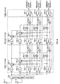
- first stage and second stage have the same configuration as illustrated in FIG. 1, the explanation of the second stage is omitted.
- antennas 11-1 and 11-2 form an array antenna, and a signal (hereinafter referred to as "first received signal") received by the antenna 11-1 is inputted to ICUs (Interference Canceling Units) 12-1 to 12-3 and a delayer 13-1. Similarly, a signal (hereinafter referred to as “second received signal”) received by the antenna 11-2 is inputted to ICUs (Interference Canceling Units) 12-1 to 12-3 and a delayer 13-2.
- ICUs 12-1 to 12-3 are provided to correspond to users 1 to 3, respectively, to generate replica signals in connection with the first received signal and the second received signal (hereinafter referred to as "first replica signal” and “second replica signal”, respectively).
- the first replica signals generated by ICUs 12-1 to 12-3 are inputted to adders 14-1 and 15-1 and the second replica signal generated by ICUs 12-1 to 12-3 are inputted to adders 14-2 and 15-2.
- the configuration of ICUs 12-1 to 12-3 will be described later.
- the delayers 13-1 and 13-2 delay the received signals by processing time of ICUs 12-1 to 12-3, and each outputs the resultant to each of the adders 14-1 and 14-2.
- the first replica signal of each of the respective users 1 to 3 is subtracted from the first signal.
- the second replica signal of each of the respective users 1 to 3 is subtracted from the second signal. This cancels all replica signals of all users from the received signals of the respective antennas.
- the output signals of adders 14-1 and 14-2 from which the replica signals of all users are canceled from the received signals are referred to as a first residual signal and a second residual signal, respectively.
- the first residual signal and the second residual signal are inputted to adders 15-1 and 15-2 and the delayers 13-1 and 13-2 of the second stage.
- the adder 15-1 adds the first replica signal and the first residual signal on a user-by-user basis .
- the adder 15-2 adds the second replica signal and the second residual signal on a user-by-user basis. This cancels the interference signal from the received signal on an antenna-by-antenna basis so as to obtain a desired signal. Namely, for example, when attention is paid to user 1, the signal of user 2 and the signal of user 3, which cause interference with user 1, are eliminated from the received signal to obtain a desired signal about user 1 every antenna. The same is applied to the signal of user 2 and the signal of user 3. The obtained desired signals are inputted to ICUs 12-1 to 12-3 of the second stage, respectively.
- the same processing as performed in the first stage is repeated in the second stage, so that the accuracy of replica signal is improved and that of the interference signal cancellation is improved.
- the more the number of stages are increased the more the inference signals about the respective users sent from the other users are canceled.
- the output signals of the adders 15-1 and 15-2 of the second stage are demodulated by the ICUs 16-1 to 16-3. This obtains demodulated signals 1 to 3 of the users 1 to 3.
- the configuration of each of the ICUs 16-1 to 16-3 will be described later.
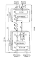
- FIG. 2 is a block diagram illustrating a schematic configuration of ICU 12-1 illustrated in FIG. 1
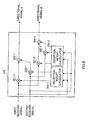
- FIG. 3 is a block diagram illustrating a schematic configuration of ICU 16-1 illustrated in FIG. 1.
- the ICU 12-1 is divided into a front stage S1 where the signals received by the respective antennas 11-1 and 11-2 are subjected to despreading and then the resultants are multiplied by reception weights of the receptive antennas, respectively; a middle stage S2 where RAKE combining and temporary determination are carried out; and a back stage S3 where the signal subjected to temporally determination is multiplied by a replica weight to perform re-spreading so as to generate a replica signal.
- the first signal received by the antenna 11-1 is inputted to a despreader 21-1 and the second signal received by antenna 11-2 is inputted to a despreader 21-2.
- the despreader 21-1 provides despreading to the first received signal to generate a despread signal X1.
- the despreader 21-2 provides despreading to the second received signal to generate a despread signal X2.
- Despread signals X1 and X2 are inputted to multipliers 22-1, 22-2, and a reception weight calculator 23.
- the reception weight calculator 23 calculates weights W1 and W2 of each antenna, and outputs the resultants to multipliers 22-1 and 22-1, and a complex conjugate calculator 30-1 and 30-2.
- the RAKE combiner 27 provides RAKE combining to the signals of the respective paths P1 to P3 subjected to array combining, and a determining device 28 performs temporarily determination to the RAKE combined signal outputted from the RAKE combiner 27.
- a signal d which has been subjected to temporary determination and which outputted from the determining device 28, is inputted to the multiplier 29 of the back stage S3.
- the multiplier 29 of the back stage S3 multiplies the signal d subjected to temporary determination by the channel estimation value h a for each of paths P1 to P3, and the resultants are inputted to multipliers 31-1 and 31-2, respectively.
- the multipliers 31-1 and 31-2 multiply the output signals of the multiplier 29 by the complex conjugates W1* and W2* of reception, respectively. This obtains replica signals Xr1 and XR2 corresponding to X1 and X2 respectively.
- the adder 33-1 adds the replica signal Xr1, which has been re-spread for each of paths P1 to P3, to generate a first replica signal and outputs the first replica signal to an adder 15-1.
- the adder 33-2 adds the replica signal Xr2, which has been re-spread for each of paths P1 to P3, to generate a second replica signal and outputs the second replica signal to an adder 15-2.
- the ICU 16-1 of the third stage has substantially the same configuration as that of the front stage S1 of the ICU 12-1 and that of the middle stage S2. Accordingly, the same reference numerals are added to the same configuration parts as those of the ICU12-1 of FIG. 2, and the explanation of the ICU 16-1 of the third stage will be omitted.
- the output signal of the determining device 28 of the ICU 16-1 is outputted to an external apparatus (not shown) as a demodulation signal.
- the conventional signal canceling apparatus generates the replica signal every antenna that form the array antenna so as to improve the reduction in the amount of calculations and the circuit scale.
- JP-A-101904905 discloses a multistage interference canceller equipment and interference canceller method for use, for example in CDMA multibeam-antenna communication system including in each stage an interference canceller unit which has a replica signal generator which generates from an input beam signal a first interference replica signal and output a first error signal and an interference removal unit which receives from another replica signal generator a second interference replica signal, multiplies that second interference replica signal by conversion coefficients and subtracts an obtained signal from the first interference replica signal to produce a second error signal so that an error signal is generated for each signal beam from the interference replica signals of a local signal beam and other signal beams to eliminate interference.
- an interference canceller unit which has a replica signal generator which generates from an input beam signal a first interference replica signal and output a first error signal and an interference removal unit which receives from another replica signal generator a second interference replica signal, multiplies that second interference replica signal by conversion coefficients and subtracts an obtained signal from the first interference replica signal to produce a second error signal so that an error signal is generated for
- JP-A-11266180 discloses an array antenna system of a wireless base station in a CDMA mobile communication having a beam former for forming a plurality of electric beams by applying a beam forming to multipath signals received by a plurality of antenna elements of an array antenna and inputting the beams to despreading/delay-adjusting units (fingers) provided for respective path of multipaths.
- Each finger despreads each of the plurality of beams input thereto.
- a beam selector selects despread signals for which desired signal components are large from all beams of all paths, a combiner weights and combines the selected despread signals, and a decision unit decides data based upon the combine signal.
- It is an object of the present invention is to provide an interference signal canceling apparatus, which is used in combination with an array antenna and which has a small amount of calculations and a small circuit scale, and its interference signal canceling method.
- this embodiment explains a case in which the signals, which are transmitted from the respective users and which come via the respective paths, are divided into some groups based on the direction of arrival to form a directivity on a group-by-group basis and to perform array combining.
- antennas 101-1 and 101-2 form an array antenna, and a signal (hereinafter referred to as “first received signal”) received by the antenna 101-1 and a signal (hereinafter referred to as “second received signal”) received by the antenna 101-2 are inputted to an adaptive array section 102.
- first received signal a signal received by the antenna 101-1
- second received signal a signal received by the antenna 101-2
- the adder 310-1 adds the replica signal Xr belonging to the directivity A among the replica signals Xr to generate a replica signal A, and outputs the replica signal A to an adder 106-1. Similarly, the adder 310-1 adds the replica signal Xr belonging to the directivity B among the replica signals Xr to generate a replica signal B, and outputs the replica signal B to an adder 106-2.
Landscapes
- Engineering & Computer Science (AREA)
- Computer Networks & Wireless Communication (AREA)
- Signal Processing (AREA)
- Noise Elimination (AREA)
- Variable-Direction Aerials And Aerial Arrays (AREA)
- Radio Transmission System (AREA)
- Mobile Radio Communication Systems (AREA)
Claims (4)
- Mehrstufige Störsignal-Unterdrückungsvorrichtung, die Störung in einem durch eine Richtgruppenantenne kombinierten Signal unterdrückt, das von einer Gruppenantenne empfangen und je nach Richtfaktor gruppenkombiniert wird, wobei die Vorrichtung umfasst:gekennzeichnet durch:eine Störungsunterdrückungseinheit (103-1 bis 103-3), die auf jeder Stufe ein Nachbildungssignal eines Benutzers erzeugt,eine Verzögerungseinrichtung (104-1, 104-2), die auf einer anderen als einer abschließenden Stufe ein empfangenes Signal um eine Verarbeitungszeit der Störungsunterdrückungseinheit verzögert;eine Unterdrückungseinrichtung (105-1, 105-2), die Nachbildungssignale aller Benutzer aus dem empfangenen Signal jedes Richtfaktors entfernt und ein Restsignal des Benutzers gewinnt;eine Addiereinrichtung (106-1, 106-2), die das Nachbildungssigrial und das Restsignal pro Benutzer addiert und das Ergebnis an eine Störungsunterdrückungseinheit einer nächsten Stufe ausgibt, wobei die Störungsunterdrückungseinheit umfasst;eine Richtfaktor-Auswähleinrichtung (301), die das durch die Richtgruppenantenne kombinierte Signal je nach Weg auswählt;eine Entspreizungseinrichtung (302), die einen Korrelationswert zwischen dem ausgewählten, durch die Richtgruppena ntenne kombinierten Signal und einem Spreizcode erfasst;eine Kombiniereinrichtung (305), die erfasste Korrelationswerte kombiniert, um einen kombinierten Wert zu erzeugen;eine Einrichtung (306) zum vorübergehenden Bestimmen, die den kombinierten Wert vorübergehend bestimmt, um einen vorübergehenden bestimmten Wert zu erzeugen;eine Rückspreizeinrichtung (308), die den vorübergehend bestimmten Wert rückspreizt, um ein rückgespreiztes Signal zu erzeugen;eine Unterteilungseinrichtung (309), die rückgespreizte Signale für jeden Richtfaktor je nach Weg sortiert; undeine Addiereinrichtung (310-1, 310-2), die die für jeden Richtfaktor rückgespreizten Signale addiert, um ein Nachbildungssignal zu erzeugen.
- Störsignal-Unterdrückungseinrichtung nach Anspruch 1, wobei die Unterdrückungseinrichtung (105-1, 105-2) Nachbildungssignale von anderen Benutzern in dem durch die Richtgruppenantenne kombinierten Signal unterdrückt.
- Basisstationsvorrichtung mit einer Gruppenantenne (101-1, 101-2) und einer mehrstufigen Störsignal-Unterdrückungsvorrichtung nach den Ansprüchen 1 und 2.
- Störungsunterdrückungsverfahren zum Einsatz in einer mehrstufigen Störungsunterdrückungsvorrichtung, die Störung in einem durch eine Richtgruppenantenne kombinierten Signal entfernt, das von einer Gruppenantenne empfangen wird und je nach Richtfaktor gruppenkombiniert wird, wobei das Verfahren in einer Störungsunterdrückungseinheit die folgenden Schritte umfasst:gekennzeichnet durch:Eingeben einer Vielzahl gruppenkombinierter Signale, die Gruppen-Kombination je nach Richtfaktor unterzogen werden, um ein gruppenkombiniertes Signal auszuwählen, das einem Weg entspricht;Erfassen eines Korrelationswertes zwischen dem ausgewählten gruppenkombinierten Signal und einem Spreizcode;Kombinieren erfasster Korrelationswerte, um einen kombinierten Wert zu erzeugen;vorübergehendes Bestimmen des kombinierten Wertes, um einen vorübergehend bestimmten Wert zu erzeugen;Rückspreizen des vorübergehend bestimmten Wertes, um ein rückgespreiztes Signal zu erzeugen;Sortieren rückgespreizter Signale für jeden Richtfaktor je nach Weg; undAddieren der für jeden Richtfaktor sortierten rückgespreizten Signale, um ein Nachbildungssignal zu erzeugen; undUnterdrücken von Störung eines gewünschten Signals in jedem gruppenkombinierten Signal unter Verwendung der erzeugten Nachbildungssignale.
Applications Claiming Priority (3)
| Application Number | Priority Date | Filing Date | Title |
|---|---|---|---|
| JP2000010877 | 2000-01-19 | ||
| JP2000010877A JP3515033B2 (ja) | 2000-01-19 | 2000-01-19 | 干渉信号除去装置及び干渉信号除去方法 |
| PCT/JP2001/000205 WO2001054328A1 (en) | 2000-01-19 | 2001-01-15 | Interference signal removing device and interference signal removing method |
Publications (3)
| Publication Number | Publication Date |
|---|---|
| EP1164735A1 EP1164735A1 (de) | 2001-12-19 |
| EP1164735A4 EP1164735A4 (de) | 2002-11-05 |
| EP1164735B1 true EP1164735B1 (de) | 2005-11-02 |
Family
ID=18538833
Family Applications (1)
| Application Number | Title | Priority Date | Filing Date |
|---|---|---|---|
| EP01900770A Expired - Lifetime EP1164735B1 (de) | 2000-01-19 | 2001-01-15 | Verfahren und vorrichtung zur beseitigung von störsignalen |
Country Status (7)
| Country | Link |
|---|---|
| US (1) | US6944208B2 (de) |
| EP (1) | EP1164735B1 (de) |
| JP (1) | JP3515033B2 (de) |
| CN (1) | CN1153392C (de) |
| AU (1) | AU2554001A (de) |
| DE (1) | DE60114511T2 (de) |
| WO (1) | WO2001054328A1 (de) |
Families Citing this family (13)
| Publication number | Priority date | Publication date | Assignee | Title |
|---|---|---|---|---|
| JP2002374227A (ja) * | 2001-06-13 | 2002-12-26 | Nec Corp | マルチユーザ干渉除去装置 |
| GB2384662B (en) * | 2002-01-25 | 2004-03-24 | Toshiba Res Europ Ltd | Receiver processing systems |
| GB2384661B (en) * | 2002-01-25 | 2005-04-20 | Toshiba Res Europ Ltd | Receiver processing systems |
| GB2384664B (en) | 2002-01-25 | 2004-12-22 | Toshiba Res Europ Ltd | Receiver processing systems |
| GB2384660B (en) * | 2002-01-25 | 2004-11-17 | Toshiba Res Europ Ltd | Reciever processing systems |
| GB2384665B (en) | 2002-01-25 | 2004-11-17 | Toshiba Res Europ Ltd | Reciever processing systems |
| WO2004088867A1 (ja) * | 2003-03-31 | 2004-10-14 | Fujitsu Limited | 受信装置 |
| US7437135B2 (en) | 2003-10-30 | 2008-10-14 | Interdigital Technology Corporation | Joint channel equalizer interference canceller advanced receiver |
| US7400692B2 (en) | 2004-01-14 | 2008-07-15 | Interdigital Technology Corporation | Telescoping window based equalization |
| EP1722499B1 (de) * | 2004-03-05 | 2011-02-16 | NTT DoCoMo, Inc. | Empfängervorrichtung, empfangsverfahren und drahtloses kommunikationssystem |
| US8195241B2 (en) | 2009-12-23 | 2012-06-05 | Northrop Grumman Systems Corporation | High-performance cellular telephone receiver |
| JP7774357B1 (ja) * | 2025-03-21 | 2025-11-21 | インターステラテクノロジズ株式会社 | フェーズドアレイアンテナ及び制御方法 |
| JP7774356B1 (ja) * | 2025-03-21 | 2025-11-21 | インターステラテクノロジズ株式会社 | フェーズドアレイアンテナ及びキャリブレーション方法 |
Family Cites Families (11)
| Publication number | Priority date | Publication date | Assignee | Title |
|---|---|---|---|---|
| JP3311943B2 (ja) | 1996-10-18 | 2002-08-05 | 松下電器産業株式会社 | 干渉信号除去装置 |
| JPH10190495A (ja) * | 1996-12-20 | 1998-07-21 | Fujitsu Ltd | 干渉キャンセラ |
| JPH11331125A (ja) | 1997-12-04 | 1999-11-30 | Sanyo Electric Co Ltd | 無線受信システム |
| JPH11168408A (ja) * | 1997-12-05 | 1999-06-22 | Fujitsu Ltd | 干渉キャンセラ装置 |
| JP2991179B2 (ja) * | 1998-01-08 | 1999-12-20 | 日本電気株式会社 | Cdmaマルチユーザ受信装置 |
| JP3328930B2 (ja) * | 1998-02-13 | 2002-09-30 | 日本電気株式会社 | 適応受信装置 |
| JPH11251959A (ja) | 1998-03-05 | 1999-09-17 | Fujitsu Ltd | 干渉キャンセラ装置及び無線通信装置 |
| JPH11266180A (ja) | 1998-03-18 | 1999-09-28 | Fujitsu Ltd | 無線基地局のアレーアンテナシステム |
| JP2965202B1 (ja) * | 1998-04-07 | 1999-10-18 | 日本電気株式会社 | マルチユーザ受信装置及びcdma通信システム |
| JP2970656B1 (ja) * | 1998-06-25 | 1999-11-02 | 日本電気株式会社 | Ds−cdmaマルチユーザ干渉キャンセラ |
| JP3800382B2 (ja) * | 1998-09-04 | 2006-07-26 | 富士通株式会社 | 干渉キャンセラにおける伝搬路推定方法及び干渉除去装置 |
-
2000
- 2000-01-19 JP JP2000010877A patent/JP3515033B2/ja not_active Expired - Fee Related
-
2001
- 2001-01-15 DE DE2001614511 patent/DE60114511T2/de not_active Expired - Lifetime
- 2001-01-15 WO PCT/JP2001/000205 patent/WO2001054328A1/ja not_active Ceased
- 2001-01-15 AU AU25540/01A patent/AU2554001A/en not_active Abandoned
- 2001-01-15 US US09/936,727 patent/US6944208B2/en not_active Expired - Lifetime
- 2001-01-15 CN CNB018000541A patent/CN1153392C/zh not_active Expired - Fee Related
- 2001-01-15 EP EP01900770A patent/EP1164735B1/de not_active Expired - Lifetime
Also Published As
| Publication number | Publication date |
|---|---|
| DE60114511T2 (de) | 2006-06-01 |
| DE60114511D1 (de) | 2005-12-08 |
| AU2554001A (en) | 2001-07-31 |
| EP1164735A4 (de) | 2002-11-05 |
| EP1164735A1 (de) | 2001-12-19 |
| WO2001054328A1 (en) | 2001-07-26 |
| CN1358371A (zh) | 2002-07-10 |
| US6944208B2 (en) | 2005-09-13 |
| JP3515033B2 (ja) | 2004-04-05 |
| CN1153392C (zh) | 2004-06-09 |
| JP2001203593A (ja) | 2001-07-27 |
| US20030067971A1 (en) | 2003-04-10 |
Similar Documents
| Publication | Publication Date | Title |
|---|---|---|
| JP2914445B2 (ja) | Cdma適応受信装置 | |
| US6069912A (en) | Diversity receiver and its control method | |
| US7106785B2 (en) | Adaptive antenna reception apparatus with weight updated adaptively | |
| US6657590B2 (en) | Adaptive antenna reception apparatus using reception signals by arrays antennas | |
| US7499484B2 (en) | Method for 2D antenna rake combining in a code division multiple access system | |
| JP3619729B2 (ja) | 無線受信装置および無線受信方法 | |
| EP0949769A1 (de) | CDMA Empfangsvorrichtung und Kommunikationssystem mit adaptiver Antenne | |
| EP1164735B1 (de) | Verfahren und vorrichtung zur beseitigung von störsignalen | |
| JP2002353866A (ja) | 干渉キャンセラ | |
| EP0936755B1 (de) | Adaptative Empfangsvorrichtung mit Gruppenantenne | |
| CN1802771B (zh) | 自适应天线接收方法和自适应天线接收机 | |
| JP3328930B2 (ja) | 適応受信装置 | |
| KR100296053B1 (ko) | 시디엠에이 적응배열 안테나 시스템의 레이크 수신기 | |
| JP3898061B2 (ja) | 干渉キャンセラ装置 | |
| JP3452253B2 (ja) | アダプティブ・アレイを用いたcdma受信装置 |
Legal Events
| Date | Code | Title | Description |
|---|---|---|---|
| PUAI | Public reference made under article 153(3) epc to a published international application that has entered the european phase |
Free format text: ORIGINAL CODE: 0009012 |
|
| 17P | Request for examination filed |
Effective date: 20011010 |
|
| AK | Designated contracting states |
Kind code of ref document: A1 Designated state(s): AT BE CH CY DE DK ES FI FR GB GR IE IT LI LU MC NL PT SE TR |
|
| AX | Request for extension of the european patent |
Free format text: AL;LT;LV;MK;RO;SI |
|
| A4 | Supplementary search report drawn up and despatched | ||
| AK | Designated contracting states |
Kind code of ref document: A4 Designated state(s): AT BE CH CY DE DK ES FI FR GB GR IE IT LI LU MC NL PT SE TR |
|
| A4 | Supplementary search report drawn up and despatched |
Effective date: 20021105 |
|
| RIC1 | Information provided on ipc code assigned before grant |
Free format text: 7H 04J 13/04 A, 7H 04B 1/10 B, 7H 01Q 3/26 B, 7H 04B 1/707 B, 7H 04B 7/08 B |
|
| 17Q | First examination report despatched |
Effective date: 20030331 |
|
| RBV | Designated contracting states (corrected) |
Designated state(s): DE FR GB |
|
| GRAP | Despatch of communication of intention to grant a patent |
Free format text: ORIGINAL CODE: EPIDOSNIGR1 |
|
| GRAS | Grant fee paid |
Free format text: ORIGINAL CODE: EPIDOSNIGR3 |
|
| GRAA | (expected) grant |
Free format text: ORIGINAL CODE: 0009210 |
|
| AK | Designated contracting states |
Kind code of ref document: B1 Designated state(s): DE FR GB |
|
| REG | Reference to a national code |
Ref country code: GB Ref legal event code: FG4D |
|
| REF | Corresponds to: |
Ref document number: 60114511 Country of ref document: DE Date of ref document: 20051208 Kind code of ref document: P |
|
| ET | Fr: translation filed | ||
| PLBE | No opposition filed within time limit |
Free format text: ORIGINAL CODE: 0009261 |
|
| STAA | Information on the status of an ep patent application or granted ep patent |
Free format text: STATUS: NO OPPOSITION FILED WITHIN TIME LIMIT |
|
| 26N | No opposition filed |
Effective date: 20060803 |
|
| REG | Reference to a national code |
Ref country code: FR Ref legal event code: CD Owner name: PANASONIC CORPORATION, JP Effective date: 20131217 |
|
| REG | Reference to a national code |
Ref country code: GB Ref legal event code: 732E Free format text: REGISTERED BETWEEN 20140925 AND 20141001 |
|
| REG | Reference to a national code |
Ref country code: FR Ref legal event code: PLFP Year of fee payment: 15 |
|
| REG | Reference to a national code |
Ref country code: DE Ref legal event code: R082 Ref document number: 60114511 Country of ref document: DE Representative=s name: EISENFUEHR SPEISER PATENTANWAELTE RECHTSANWAEL, DE |
|
| REG | Reference to a national code |
Ref country code: GB Ref legal event code: 732E Free format text: REGISTERED BETWEEN 20150129 AND 20150204 |
|
| REG | Reference to a national code |
Ref country code: DE Ref legal event code: R079 Ref document number: 60114511 Country of ref document: DE Free format text: PREVIOUS MAIN CLASS: H04J0013040000 Ipc: H04J0013100000 |
|
| REG | Reference to a national code |
Ref country code: DE Ref legal event code: R082 Ref document number: 60114511 Country of ref document: DE Representative=s name: EISENFUEHR SPEISER PATENTANWAELTE RECHTSANWAEL, DE Effective date: 20150109 Ref country code: DE Ref legal event code: R081 Ref document number: 60114511 Country of ref document: DE Owner name: INVENTERGY, INC. (N.D.GES.D. STAATES DELAWARE), US Free format text: FORMER OWNER: PANASONIC CORPORATION, KADOMA-SHI, OSAKA, JP Effective date: 20150109 Ref country code: DE Ref legal event code: R079 Ref document number: 60114511 Country of ref document: DE Free format text: PREVIOUS MAIN CLASS: H04J0013040000 Ipc: H04J0013100000 Effective date: 20150427 Ref country code: DE Ref legal event code: R081 Ref document number: 60114511 Country of ref document: DE Owner name: INVT SPE LLC (N.D.GES.D. STAATES DELAWARE), SA, US Free format text: FORMER OWNER: PANASONIC CORPORATION, KADOMA-SHI, OSAKA, JP Effective date: 20150109 |
|
| REG | Reference to a national code |
Ref country code: FR Ref legal event code: TP Owner name: INVENTERGY, INC., US Effective date: 20151027 |
|
| REG | Reference to a national code |
Ref country code: FR Ref legal event code: PLFP Year of fee payment: 16 |
|
| REG | Reference to a national code |
Ref country code: FR Ref legal event code: PLFP Year of fee payment: 17 |
|
| PGFP | Annual fee paid to national office [announced via postgrant information from national office to epo] |
Ref country code: FR Payment date: 20161215 Year of fee payment: 17 |
|
| PGFP | Annual fee paid to national office [announced via postgrant information from national office to epo] |
Ref country code: DE Payment date: 20170110 Year of fee payment: 17 |
|
| PGFP | Annual fee paid to national office [announced via postgrant information from national office to epo] |
Ref country code: GB Payment date: 20170111 Year of fee payment: 17 |
|
| REG | Reference to a national code |
Ref country code: DE Ref legal event code: R082 Ref document number: 60114511 Country of ref document: DE Representative=s name: EISENFUEHR SPEISER PATENTANWAELTE RECHTSANWAEL, DE Ref country code: DE Ref legal event code: R081 Ref document number: 60114511 Country of ref document: DE Owner name: INVT SPE LLC (N.D.GES.D. STAATES DELAWARE), SA, US Free format text: FORMER OWNER: INVENTERGY, INC. (N.D.GES.D. STAATES DELAWARE), CAMPBELL, CALIF., US |
|
| REG | Reference to a national code |
Ref country code: GB Ref legal event code: 732E Free format text: REGISTERED BETWEEN 20171214 AND 20171222 |
|
| REG | Reference to a national code |
Ref country code: FR Ref legal event code: TP Owner name: INVT SPE LLC, US Effective date: 20171018 |
|
| REG | Reference to a national code |
Ref country code: DE Ref legal event code: R119 Ref document number: 60114511 Country of ref document: DE |
|
| GBPC | Gb: european patent ceased through non-payment of renewal fee |
Effective date: 20180115 |
|
| PG25 | Lapsed in a contracting state [announced via postgrant information from national office to epo] |
Ref country code: DE Free format text: LAPSE BECAUSE OF NON-PAYMENT OF DUE FEES Effective date: 20180801 Ref country code: FR Free format text: LAPSE BECAUSE OF NON-PAYMENT OF DUE FEES Effective date: 20180131 |
|
| REG | Reference to a national code |
Ref country code: FR Ref legal event code: ST Effective date: 20180928 |
|
| PG25 | Lapsed in a contracting state [announced via postgrant information from national office to epo] |
Ref country code: GB Free format text: LAPSE BECAUSE OF NON-PAYMENT OF DUE FEES Effective date: 20180115 |