EP1166910B1 - Apparatus and method for manufacturing hollow shafts - Google Patents
Apparatus and method for manufacturing hollow shafts Download PDFInfo
- Publication number
- EP1166910B1 EP1166910B1 EP00650162A EP00650162A EP1166910B1 EP 1166910 B1 EP1166910 B1 EP 1166910B1 EP 00650162 A EP00650162 A EP 00650162A EP 00650162 A EP00650162 A EP 00650162A EP 1166910 B1 EP1166910 B1 EP 1166910B1
- Authority
- EP
- European Patent Office
- Prior art keywords
- shaft
- rollers
- seam
- welding
- fixed axis
- Prior art date
- Legal status (The legal status is an assumption and is not a legal conclusion. Google has not performed a legal analysis and makes no representation as to the accuracy of the status listed.)
- Expired - Lifetime
Links
Images


Classifications
-
- B—PERFORMING OPERATIONS; TRANSPORTING
- B23—MACHINE TOOLS; METAL-WORKING NOT OTHERWISE PROVIDED FOR
- B23K—SOLDERING OR UNSOLDERING; WELDING; CLADDING OR PLATING BY SOLDERING OR WELDING; CUTTING BY APPLYING HEAT LOCALLY, e.g. FLAME CUTTING; WORKING BY LASER BEAM
- B23K11/00—Resistance welding; Severing by resistance heating
- B23K11/02—Pressure butt welding
-
- B—PERFORMING OPERATIONS; TRANSPORTING
- B21—MECHANICAL METAL-WORKING WITHOUT ESSENTIALLY REMOVING MATERIAL; PUNCHING METAL
- B21C—MANUFACTURE OF METAL SHEETS, WIRE, RODS, TUBES, PROFILES OR LIKE SEMI-MANUFACTURED PRODUCTS OTHERWISE THAN BY ROLLING; AUXILIARY OPERATIONS USED IN CONNECTION WITH METAL-WORKING WITHOUT ESSENTIALLY REMOVING MATERIAL
- B21C37/00—Manufacture of metal sheets, rods, wire, tubes, profiles or like semi-manufactured products, not otherwise provided for; Manufacture of tubes of special shape
- B21C37/06—Manufacture of metal sheets, rods, wire, tubes, profiles or like semi-manufactured products, not otherwise provided for; Manufacture of tubes of special shape of tubes or metal hoses; Combined procedures for making tubes, e.g. for making multi-wall tubes
- B21C37/08—Making tubes with welded or soldered seams
- B21C37/0815—Making tubes with welded or soldered seams without continuous longitudinal movement of the sheet during the bending operation
-
- B—PERFORMING OPERATIONS; TRANSPORTING
- B21—MECHANICAL METAL-WORKING WITHOUT ESSENTIALLY REMOVING MATERIAL; PUNCHING METAL
- B21C—MANUFACTURE OF METAL SHEETS, WIRE, RODS, TUBES, PROFILES OR LIKE SEMI-MANUFACTURED PRODUCTS OTHERWISE THAN BY ROLLING; AUXILIARY OPERATIONS USED IN CONNECTION WITH METAL-WORKING WITHOUT ESSENTIALLY REMOVING MATERIAL
- B21C37/00—Manufacture of metal sheets, rods, wire, tubes, profiles or like semi-manufactured products, not otherwise provided for; Manufacture of tubes of special shape
- B21C37/06—Manufacture of metal sheets, rods, wire, tubes, profiles or like semi-manufactured products, not otherwise provided for; Manufacture of tubes of special shape of tubes or metal hoses; Combined procedures for making tubes, e.g. for making multi-wall tubes
- B21C37/08—Making tubes with welded or soldered seams
- B21C37/0822—Guiding or aligning the edges of the bent sheet
-
- B—PERFORMING OPERATIONS; TRANSPORTING
- B21—MECHANICAL METAL-WORKING WITHOUT ESSENTIALLY REMOVING MATERIAL; PUNCHING METAL
- B21C—MANUFACTURE OF METAL SHEETS, WIRE, RODS, TUBES, PROFILES OR LIKE SEMI-MANUFACTURED PRODUCTS OTHERWISE THAN BY ROLLING; AUXILIARY OPERATIONS USED IN CONNECTION WITH METAL-WORKING WITHOUT ESSENTIALLY REMOVING MATERIAL
- B21C37/00—Manufacture of metal sheets, rods, wire, tubes, profiles or like semi-manufactured products, not otherwise provided for; Manufacture of tubes of special shape
- B21C37/06—Manufacture of metal sheets, rods, wire, tubes, profiles or like semi-manufactured products, not otherwise provided for; Manufacture of tubes of special shape of tubes or metal hoses; Combined procedures for making tubes, e.g. for making multi-wall tubes
- B21C37/15—Making tubes of special shape; Making tube fittings
- B21C37/16—Making tubes with varying diameter in longitudinal direction
- B21C37/18—Making tubes with varying diameter in longitudinal direction conical tubes
- B21C37/185—Making tubes with varying diameter in longitudinal direction conical tubes starting from sheet material
-
- B—PERFORMING OPERATIONS; TRANSPORTING
- B21—MECHANICAL METAL-WORKING WITHOUT ESSENTIALLY REMOVING MATERIAL; PUNCHING METAL
- B21D—WORKING OR PROCESSING OF SHEET METAL OR METAL TUBES, RODS OR PROFILES WITHOUT ESSENTIALLY REMOVING MATERIAL; PUNCHING METAL
- B21D5/00—Bending sheet metal along straight lines, e.g. to form simple curves
- B21D5/06—Bending sheet metal along straight lines, e.g. to form simple curves by drawing procedure making use of dies or forming-rollers, e.g. making profiles
- B21D5/10—Bending sheet metal along straight lines, e.g. to form simple curves by drawing procedure making use of dies or forming-rollers, e.g. making profiles for making tubes
- B21D5/12—Bending sheet metal along straight lines, e.g. to form simple curves by drawing procedure making use of dies or forming-rollers, e.g. making profiles for making tubes making use of forming-rollers
-
- B—PERFORMING OPERATIONS; TRANSPORTING
- B23—MACHINE TOOLS; METAL-WORKING NOT OTHERWISE PROVIDED FOR
- B23K—SOLDERING OR UNSOLDERING; WELDING; CLADDING OR PLATING BY SOLDERING OR WELDING; CUTTING BY APPLYING HEAT LOCALLY, e.g. FLAME CUTTING; WORKING BY LASER BEAM
- B23K2101/00—Articles made by soldering, welding or cutting
- B23K2101/04—Tubular or hollow articles
Definitions
- This invention relates to the manufacture of hollow tapered shafts having a longitudinal seam.
- a method and an apparatus according to the preambles of claims 1 and 4 are e.g. known from FR-A-926 683.
- the manufacture of such hollow shafts generally involves forming a flat sheet of material into a generally cylindrical structure having an open seam but which is nevertheless in substantially the same shape as the desired finished shaft (referred to herein as an "open shaft").
- the forming may be done using a series of stamping operations with curved male and female stamping dies, or the flat sheet may be fed through a series of roll forming machines which progressively bend the sheet.
- the open shaft with its open seam, is then fed from the roll forming machines to a welding machine which closes and welds the open seam to provide a closed shaft.
- Fig. 1 shows a known method of closing the seam.
- An open shaft 10 is fed between a pair of cylindrical rollers 12,14 which between them compress the shaft to close the seam 16. Welding occurs in a zone 18 where the opposed edges 20 of the seam meet due to the seam 16 being forced closed by the rollers 12,14.
- Fig. 2 shows the rollers of Fig. 1 in sectional elevation, along the line II-II in Fig. 1.
- the rollers 12,14 have axes of rotation 22 parallel to one another and perpendicular to the axis of the shaft 10.
- the shaft 10 moves along the direction of its axis as indicated by arrow 24.
- the cylindrical rollers 12,14 rotate in the directions indicated by arrows 26 and 28 (Fig. 1).
- each roller 12,14 are immediately adjacent one another with their curved surfaces 30 close to one another.
- each roller has a groove 32 in its curved surface 30 defining one half of the cross section of the closed shaft.
- a substantially circular recess accommodates and forces closed the shaft to allow the opposed edges 20 to be welded to one another.
- the shaft is gripped at a pair of grip holes 34 (Fig. 1) by a pair of jaws (not shown) which are mounted on a driven carriage.
- the carriage is driven away from the rollers along the direction of arrow 24 to pull the shaft through the rollers.
- a large force must be generated to pull the shaft through the rollers to overcome the retarding force on the rollers. This force increases as the taper of the shaft increases, because the amount of force required to close a large diameter shaft is greater than that required to close a small diameter shaft.
- the grip holes 34 must be spaced from the tip of the shaft by a sufficient distance x (Fig. 1) to prevent the jaws ripping through the metal between the holes 34 and the tip.
- Electrical resistance welding is accomplished by applying a current along the opposed edges 20 in the zone 18, such that at the point where the edges meet, the metal melts and a join is created.
- the shaft must however be fed through the rollers to the point where the jaws can grip the grip holes 34 (as in Fig. 1) before continuous welding can begin. This necessarily means that there is a significant length of unusable shaft near the tip which must be cut away from the finished shaft.
- rollers 12,14 must be made of hardened steel (or other similar hardened material, in order to generate the required closing forces consistently. They are machined from a single mass of steel and then undergo heating and cooling to achieve the correct hardness. Such rollers are very difficult to manufacture correctly due to their scale.
- the hardening process requires that a very large mass of steel be machined, and then heated and cooled uniformly without cracking.
- One commonly experiences failure rates of 50% in manufacturing these rollers which means that the cost of successfully manufacturing rollers is increased far above the already high cost involved in machining and tempering a steel roller of these dimensions.
- rollers also has a disadvantage in that one reaches an upper limit as the size of roller which can be realistically made, and therefore in turn, the size of shaft which can be made using the process of welding closed an open shaft which is closed by pressure rollers.
- any particular set of rollers is confined to manufacturing a single type of pole or shaft.
- the invention has as an object the provision of a welding machine and a method of welding which overcomes at least some of the disadvantages of the prior art.
- the invention provides a method of welding a hollow tapered shaft according to claim 1.
- the invention also provides a welding apparatus according to claim 4.
- the inwardly directed radial forces are applied at a plurality of discrete points on the shaft surface.
- the welding means comprises an electrical resistance welding arrangement.
- the means for applying inwardly directed radial forces to the shaft at a plurality of discrete points on the surface of the shaft comprises a plurality of pressure rollers defining an opening through which the shaft is fed, and means for varying the positions of the rollers to thereby vary the dimensions of the opening.
- a number of sets of rollers each set defining an opening, may be provided, with the shaft passing progressively through each opening in turn.
- the apparatus further comprises feeding means for moving an open shaft through said means for applying inwardly directed radial forces, whereby the open shaft is progressively closed and welded along its length.
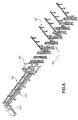
- FIG. 3 there is indicated generally at 40 an apparatus according to the present invention, comprising the following main assemblies: a transfer table 42, and inlet table 44, a centre section 46 and an outlet table 48.
- the transfer table 42 is used to hold a number of shafts to be welded, and to load these shafts in turn onto the inlet table 44.
- One such shaft 50 is shown in position on the transfer table 42.
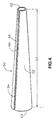
- Fig. 4 shows an open shaft 50 in perspective.
- the shaft 50 comprises a sheet 52 of material which has been formed into a generally closed cylindrical shape having an open seam 54 defined between opposed edges 56,58.
- a section of sheet steel is cut from a roll of sheet steel into a trapezoidal shape, the dimensions of which define the length 60 of the shaft, the diameters of the tip 62 and butt 64 of the shaft 50, and hence the degree of taper of the shaft 50.
- the trapezoid is formed into the closed cylindrical shape by a series of stamping operations between male and female stamping members, as is known in the art.
- the apparatus 40 In order to manufacture a closed shaft or pole from the open shaft 50, the apparatus 40 must force closed the seam 54 and weld the opposed edges 56,58 together.
- Fig. 5 shows the shaft 50 when it has been loaded onto the inlet table 44.
- the inlet table rotates the shaft until the seam is uppermost and then transports the shaft, tip first, in this orientation towards the centre section 46.
- the outlet table 48 has a drive motor 66 which drives a drawbench (not shown) to pull the tip of the shaft away from the centre section. As the shaft moves into the outlet table (Figs. 6 and 7), the seam is welded progressively closed until the closed shaft is located entirely in the outlet table (Fig. 7).
- the drawbench then disengages from the shaft, and the shaft is lowered within the outlet section (Fig. 8) to allow the drawbench to move forward to engage the tip of the next shaft, and finally, the shaft is driven out of the outlet table (Fig. 9) for further operations the nature of which will be determined by the final use of the shaft.
- Fig. 10 shows the transfer table 42 with three shafts 50 loaded thereon.
- the transfer table has five roller chain conveyors 68 driven from a common shaft 70.
- One such conveyor is shown in a simplified side elevation in Fig. 11.
- the conveyor 68 comprises a chain 72 having a number of locator pegs 74 which support the shafts 50.
- the tip 62 and butt 64 of one of the shafts 50 are identified, as is the open seam 20 of one of the other shafts.
- Chain 72 is mounted on a pair of sprocket wheels 76,78.
- the shafts 50 are carried up the transfer table towards the drive shaft 70.
- the shafts are deposited on the inlet table 44, which is shown in Fig. 10 as a series of stations, described in further detail below.
- Fig. 10 it can be seen that the three illustrated shafts rest only on four of the five conveyors 68.
- the fifth conveyor is provided to support longer shafts.
- the transfer table is provided with a locating beam 80 to align the tips 62 of the shafts and ensure that the shafts are deposited at the correct position along the inlet table 44.
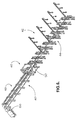
- Fig. 10 shows the positions of the inlet table 44 as a series of stations 82,84a-84c,86a-86c,88a-88c located along a datum line 89 perpendicular to the conveyors 68.
- the inlet table consists of four different types of stations which together support the shaft, orient it to a position where the seam is uppermost, and drive it towards the centre section.
- the four different types of station are defined by the types of rollers on which the shaft is supported.
- the first station (starting at the end of the inlet table 44 farthest from the centre section) is a non-powered support roller station 82 used only to support the butts of long shafts.
- the second, fifth and seventh stations are orientation roller stations 84a,84b,84c which are used to rotate the shaft about its axis until the seam is uppermost.
- the third, fourth and sixth stations are powered seamless drive roller stations 86a,86b,86c which are used to drive the shaft forward towards the centre section.
- the eighth, ninth and tenth stations are powered seamguide drive roller stations 88a,88b,88c which are used to drive the shaft forward towards the centre section while maintaining the seam uppermost.
- the four station types can be seen in elevation along the direction of the shaft axis (not shown) in Figs. 12-15.
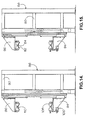
- Fig. 12 shows the non-powered support roller station 82 which comprises a support frame 90 having a pair of lower rollers 92 (of which only the closest one is visible) and a single upper roller 94.
- Each of the rollers 92,94 is in the shape of a pair of abutting frusto-conical halves which define a shallow V-shaped support for the shaft. These rollers allow the shaft to be moved along the direction of its axis towards the centre section.
- the lower and upper rollers 92,94 are mounted on a lower roller support assembly 96 and an upper roller support assembly 98, respectively, which are hydraulically driveable in a vertical direction to open and close the spacing between the rollers 92,94.
- All of the other stations similarly have a support frame 90 and lower and upper roller support assemblies 96,98 (on which different roller types are mounted), such that each of the ten stations can be opened and closed independently of the other stations.
- the lower roller support assembly 96 has four orientation rollers 100 driven by a drive chain 102.
- the orientation rollers 100 are mounted transversely to the rollers 92,94 of the non-powered support roller station 82, i.e. the axes of the orientation rollers are parallel to the axis of the shaft.
- a pair of driven orientation rollers 104 are mounted on the upper roller support assembly of the station 84.
- a proximity sensor array 105 (Fig. 10) is mounted on the support frame of station 88a to detect the seam of the shaft. When the proximity sensor detects that the seam is at the uppermost point of the shaft circumference, the orientation rollers are stopped to maintain the correct orientation of the shaft.
- Fig. 14 shows the powered seamless drive roller stations 86 which are similar to the non-powered station 82 but which have a drive motor 106 on the lower roller support assembly 94 which drives the lower pair of rollers 108 (again, only the closer of the pair can be seen in Fig. 14).
- the upper roller 110 in this station is undriven.
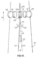
- Fig. 15 shows the powered seamguide drive roller stations 88 which are identical to the seamless drive roller stations 86 of Fig. 14 except that the upper roller 112 in Fig. 15 has a seamguide 114 extending from its centre.
- the orientation rollers 100,104 (Fig. 13) have placed the seam of the shaft uppermost and the lower and upper roller support assemblies 96,98 of station 88a are brought together to engage the shaft, so that seamguide 114 sits into the seam of the shaft and prevents the shaft from rotating on its axis as it is driven forward towards the centre section.
- the two other powered seamguide drive roller stations 88b,88c also subsequently engage the shaft in the same manner. This ensures that the welding electrodes are correctly located relative to the seam in the centre section, as will be described below.
- the operation of the inlet table is as follows.
- a set of sensors determines that the stations are correctly open to receive a shaft.
- each station will open as the butt of a shaft clears the rollers of that station, and for shafts of the length shown in Fig. 3, it is necessary therefore only for the fourth to eighth stations 84b, 84c, 86b, 86c, 88a to be open for a shaft to be loaded.
- the preceding shaft can still be in the process of being driven forward by the ninth and tenth stations 88b,88c when the sensors determine that the inlet table is ready to receive the next shaft.
- the first, second and third stations may also have to be open.
- the shaft is deposited onto the lower sets of rollers of the open stations.
- the lower and upper roller support assemblies 96,98 of the orientation roller stations 84 are then hydraulically driven together to grip the shaft.
- the shaft is raised to approximately the datum position.
- the shaft In the datum position the shaft is held horizontally with its axis pointing directly along the line of the inlet table.
- the datum line for all of the translation and rotational movements is the central axis of the shaft (and not the line of the seam which is at an angle to the central axis as determined by the taper).
- a pneumatic cylinder lowers the proximity sensor array 105 close to the upper surface of the shaft.
- the orientation rollers 100,104 are then rotated to spin the shaft about its longitudinal axis until the proximity sensor array 105 determines that the seam is uppermost.
- a seamguide (not shown) mounted adjacent to the proximity sensor array is lowered into the seam to prevent rotational slippage.
- the powered drive roller support assemblies 96,98 of stations 86b,86c,88a are brought together to engage the shaft from above and below, with the seamguide 114 of station 88a locating into the seam of the shaft.
- the orientation roller stations are then opened and return to their start positions.
- the sensor array 105 and the associated seamguide which was initially lowered to prevent slippage may also be withdrawn, as the seamguide 114 of station 88a will now hold the seam uppermost.
- the hydraulic cylinders which drive the upper and lower roller support assemblies 96,98 of the powered drive roller stations 86b,86c,88a then operate to precisely position the central axis of the shaft along the datum line. Once the shaft is accurately located, the hydraulic pressure on the roller support assemblies is relaxed so as to firmly support the shaft without gripping the shaft so tightly that frictional forces impede the translational movement of the shaft towards the centre station.
- the shaft once located, is then driven forward by the powered lower rollers of the powered drive stations 86b,86c,88a until the tip enters the centre section. Because of the inertia of a large shaft, the rollers are driven to accelerate and decelerate the shaft smoothly into the centre section 44, with sensors in the centre section detecting the approach and correct positioning of the tip of the shaft to begin welding.
- the welding process is an electrical resistance welding process in the described embodiment (although other welding techniques could be used as appropriate).
- Fig. 16 schematically illustrates the primary components of the centre section used in the electrical resistance welding process.
- Fig. 16 the shaft 50 is seen from above.
- An open seam 16 defined between opposed edges 20 is forced closed as the shaft moves in the direction of arrow 24 through an array of pressure rollers 116,118, which are represented schematically in Fig. 16.
- the array of rollers can be seen in greater detail in end elevation in Fig. 17 and in perspective in Fig. 18.
- the pressure rollers 116,118 are hydraulically operated to generate an inwardly directed radial force on the outer surface of the shaft. This compressive force causes the opposed edges to be forced into contact at a welding point indicated at 120. Thus, immediately upstream (in the direction of the inlet table, opposite to that of arrow 24), the opposed edges form an acute "V" shape.
- a finpass 122 sits within the open seam upstream of the welding point to maintain the "V" open by at least a predetermined amount, which will be dependent on the welding parameters and the properties of the steel or other material being welded. If necessary, one or more additional arrays of pressure rollers and/or finpasses may be provided to correctly close the seam at the required angle, and to exert additional closing force where required.
- a pair of welding electrodes 124,126 contact the outer surface of the shaft adjacent the opposed edges 20 in the vicinity of the "V" between the finpass 122 and the welding point 120.
- the welding electrodes are connected to a high frequency, low voltage, high current power supply.
- the high current is applied by the electrodes to the edge portions of the shaft, where it preferentially flows along one edge, through the point of contact (welding point 120) and back along the other edge.
- the localised resistance at the welding point causes the temperature to rise above the melting point of the material, and the contacting edges become molten and fuse together.
- an impeder may be located on an arm extending from the finpass mounting down through the open seam of the shaft, i.e. inside the hollow open shaft.
- the impeder is a generally cylindrical body which extends forward of the finpass to a point generally below the welding electrodes, and is filled with ferrite rods. These rods act to counteract the induced field around the circumference of the shaft, inhibiting current flow away from the circumference and thereby encouraging current flow along the "V" edges.
- the weld is strengthened by the compressive force applied by the pressure rollers, so that the molten edges are pushed together to form a raised seam 128 above and below the surface of the shaft.
- the external (visible) part of this raised seam may be removed by a scarfer while still soft, or it may be machined away at a later point in time.
- a scarfer is located just downstream of the pressure roller 116.
- roller 116 (Figs. 16 and 17) has a stepped surface defining a recess 116a. This is to accommodate the still-molten seam as it passes under the roller.
- the actual current applied will depend on the characteristics of the material being welded and the speed at which the shaft is moved past the electrodes.
- a pyrometer (not shown) located above the welding point 120 monitors the colour of the molten material (and hence the welding temperature) and the current is controlled to maintain a suitable welding temperature.
- the sequence of steps from the point at which the tip of the shaft enters the centre section is as follows.
- the position of the finpass (and impeder if present) is fixed to ensure that the finpass is correctly located to pass within the seam of the shaft as the tip enters the centre section.
- the driving rollers of the inlet table accelerate and decelerate the shaft to correctly locate the tip inside the centre section.
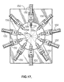
- the shaft is stopped with the tip protruding downstream of a centre plate 130 (seen from the upstream side in Figs. 17 and 18) on which the pressure rollers 116, 118 are mounted, each via its own hydraulic cylinder 132.
- Each hydraulic cylinder 132 is independently actuable to move the associated pressure roller 116,118 radially towards or away from the centre 134 (Fig. 17) of an aperture 136 in the centre plate 130.
- Fig. 19 shows the centre section in side view, with some components omitted for clarity.
- a support frame 138 is used to mount the centre plate 130, and on this centre plate the vertically mounted pressure rollers 116,118 can be seen spaced equidistantly from the datum line 89.
- Fig. 19 also shows the finpass assembly 140 on which the finpass 122 is mounted.
- the finpass assembly is hydraulically movable in a vertical direction by means of a hydraulic cylinder 142.
- a further finpass or seamguide 144 is mounted on the finpass assembly 140 in the direction of the inlet table.
- the welding assembly and the impeder are omitted for clarity.
- the welding assembly lowers into a gap 146 between the finpass assembly 140 and the pressure cylinder 116.
- a drawbench 148 (shown partially in Fig. 19) on the outlet table is equipped with a pair of jaws 150 which are actuable to grip a pair of grip holes located adjacent the tip of the shaft.
- the drawbench 148 moves along the outlet table towards the centre section as the shaft enters the inlet table, and once the tip is correctly positioned, the jaws 150 engage the grip holes at a point just beyond the centre plate 130.
- each of the pressure cylinders 118 (but not pressure cylinder 116) converges on the shaft to close the seam.
- the pressure exerted by the nine cylinders cause the meeting edges to be forced upwards, so that the shaft has a very slight "teardrop" cross section.
- pressure cylinder 116 descends to depress the meeting edges and provide a circular cross section.
- the welding electrodes 124,126 are provided on a welding assembly (shown schematically in Fig. 16 as a dotted outline 151 around the electrodes) which can be hydraulically raised and lowered.
- the welding assembly is held away from the shaft surface until the pressure cylinders 116,118 have contacted and closed the shaft.
- the hydraulic cylinder brings the welding assembly down towards the surface of the shaft.
- the electrodes are pneumatically actauble by a short distance relative to the welding assembly, so that welding contact can be made or broken instantaneously without retracting the entire welding assembly.
- the current generator When welding contact is made, cooling water is applied to the welding assembly and the current generator is sent a signal to apply a preheat current to the electrodes to preheat the welding area to e.g. 800-850°C.
- a preheat current to the electrodes to preheat the welding area to e.g. 800-850°C.
- the vector drive motor 66 on the outlet table 48 (Fig. 6) powers up and begins to accelerate the drawbench, which is holding the tip of the shaft, away from the outlet table.
- full welding power is sent to the welding electrodes, thereby heating the welding point to full welding temperature (e.g. 1250-1350°C).
- the vector drive motor is driven under computer control.
- the exact rotor position of the motor is monitored to determine the precise drawbench position relative to the centre section.
- the computer is programmed with the taper characteristics of the shaft, and hence the shaft diameter at the pressure cylinder array, welding electrode position, finpass position, and each of the inlet table stations can be determined.
- the pressure cylinders are moved outwards at the precise rate required to maintain sufficient pressure to close the shaft, taking the taper into account.
- the hydraulic cylinder controlling the welding assembly moves the welding electrodes upwards to keep contact on the shaft, and the finpass and impeder are likewise moved upwards at the appropriate rate to maintain their position relative to the seam of the shaft.
- the positions of the hydraulic cylinders controlling the roller support assemblies of the inlet table stations is also controlled by the computer and varied to account for the taper of the shaft.
- the drawbench can typically be operated at speeds up to and in excess of 25m/minute without compromising the weld quality.
- Fig. 20 shows the outlet table 48 in side elevation.
- the drawbench 148 (with its jaws 150 oriented towards the centre section) moves along a track 152 under the influence of drive motor 66 which drives a chain (not shown) around a pair of chainwheels 154.
- cradle rollers 156 are hydraulically actuated by hydraulic cylinders 157 located within the outlet table to pivot upwards to meet the shaft which drops onto the cradle rollers.
- the jaws 150 then disengage from the shaft and the cradle rollers 156 are lowered back down to the position shown in Fig. 20. Just before the cradle rollers are fully lowered, the shaft meets a set of driven rollers 158 at the base of the outlet table, and the shaft is thereby transferred onto the driven rollers (see also Fig. 8).
- the motor 166 reverses to send the drawbench back to the outlet table in preparation for the next shaft.
- the driven rollers then are actuated to transfer the shaft out of the end of the outlet table (in the manner indicated in Fig. 9) as the next shaft starts to be pulled forward by the drawbench. Because of the high speed at which the invention operates, the time taken from when the shaft is loaded onto the inlet table until it is lowered in the outlet table is of the order of 45 seconds.
- Fig. 21 shows a control circuit used to control the apparatus of the present invention.
- a silicon controlled rectifier (SCR) 160 acts as a power supply.
- Three phase input power is fed via a circuit breaker and magnetic contactor to thyristor stacks which control the output voltage from 0% to 100% by adjusting gate firing sequence, phase angle and timing.
- An automatic voltage regulator stabilises the DC output voltage and protects against input voltage fluctuations.
- Power from SCR 160 is fed to a main transformer (TR) 162 which transforms the voltage to a high voltage.
- the high voltage is fed to a high frequency oscillator unit (HF OSC) 164 which firstly converts the high voltage AC power from the transformer 162 to DC, and then feeds this DC voltage to an oscillator to generate a high frequency output.
- This output is then fed to a high frequency output transformer (o/p TR) 166 which converts the supply to low voltage, high current power which is applied to the weld contact tips or welding electrodes 124,126.
- o/p TR high frequency output transformer
- a pyrometer 168 located above the welding zone monitors the colour of the weld and feeds a signal to a programmable logic controller (Mitsubishi Controller) 170 which varies the operation of the transformer 162 to maintain the correct welding temperature by varying the power supply to the electrodes.
- a programmable logic controller Mitsubishi Controller
- a Programmable Industrial Computer (Giddings and Lewis PIC 900) 172 includes hardware and software elements.
- the hardware includes a system rack, hardware modules and I/O connectors under the control of a CPU.
- the software interacts with an operator input and output, such as a touch screen, to generate commands in response to operator input and program instructions, these commands being sent to hardware output modules which in turn control physical devices connected to the PIC.
- two touch screen operator interfaces 174,176 are provided.
- Screen 174 is used to control the operation of controller 170, to change welding parameters (such as welding temperature).
- Screen 176 is used to control PIC 172 to change motion controls for the various hydraulic drives, pneumatic drives and motors of the apparatus, all of which are under the control of the PIC.
- the Cegelec vector drive unit 178 uses motor speed or slip angle information and a model of motor characteristics to calculate the output waveform which will maintain an optimum field orientation for the coils of motor 180 under all motor speeds and loads.
- Motor 180 is a 6 pole, 1000 rpm 449TC frame size Baldor motor having a 200 HP output, and a flange mounted planetary gearbox assembly.
- the position of the drawbench as calculated by the vector drive unit is used to control the positions of the inlet table roller assemblies, finpass assembly, welding assembly and pressure rollers.
- Each of these uses a hydraulic cylinder 182 having an associated AEC (Absolute to Encoder Converter) 184.
- the AEC 184 takes the output of a single linear displacement transducer and converts the signal to incremental encoder quadrature (square-wave-in-quadrature).
- the AEC takes two positions from the transducer. The difference or change is converted into quadrature pulses which are then used to control the movement of the hydraulic cylinders.
- the system allows a positional accuracy of 0.01 mm.
- the PIC nay be programmed to operate in one of two modes.
- the cylinders are slaved to the position of the shaft, using the feedback from the linear displacement transducers to position the cylinders at the required setting for the current drawbench position. It is this mode which was described above.
- the pressure rollers are positioned by the controller to their starting positions, and the PIC drops out of positional lock and instead goes to open loop control, applying a predetermined pressure to the hydraulic feed valves according to a predetermined voltage ramp.
- the amount of pressure to be applied to the hydraulic feed valves to maintain the correct roller pressure as the shaft moves through the output table can be determined over time.
- the two modes can be used independently of one another on the various cylinders, i.e. the same mode need not be used on all cylinders.
- the additional rollers can be brought on line gradually as the taper increases. These additional rollers may be operated under pressure control to avoid a sudden increase in pressure which might damage or distort the shaft.
- the datum line of the system is the centre line of the shaft
- the correct positions of the positions of the pressure cylinders, welding assembly, finpass assembly and inlet table stations can be calculated based on the drawbench position, once the tip diameter, shaft length and butt diameter are known.
- the system is thus extremely versatile in allowing for different types of shafts to be welded.
- the dimensions of the cylindrical rollers of Fig. 1 also impose a minimum amount of wastage between the tip of the shaft and the beginning of the weld (which can only start after the jaws can engage the grip holes).
- the welding apparatus is at one side of the closely spaced rollers, and the grip holes must be on the opposite side when welding begins.
- the diameter of the rollers therefore has a significant effect on the length of unwelded seam at the tip end of the shaft.
- the jaws on the present embodiment can be spaced just past the pressure rollers, with the welding electrodes just in front of these rollers, reducing the amount of wastage by an order of magnitude.
- shafts which can be manufactured by the apparatus and method of the invention are not constrained by an upper limit on large roller sizes (as in the case of apparatuses of the Fig. 1 type).
- Extreme tapers can be accounted for by optionally reducing the number of pressure rollers in contact with the shaft at the beginning of the weld and bringing further rollers into play as the diameter of the shaft increases.
Landscapes
- Engineering & Computer Science (AREA)
- Mechanical Engineering (AREA)
- Extrusion Moulding Of Plastics Or The Like (AREA)
- Butt Welding And Welding Of Specific Article (AREA)
- Shafts, Cranks, Connecting Bars, And Related Bearings (AREA)
- Lining Or Joining Of Plastics Or The Like (AREA)
- Rolls And Other Rotary Bodies (AREA)
- Arc Welding In General (AREA)
- Diaphragms For Electromechanical Transducers (AREA)
- Meat, Egg Or Seafood Products (AREA)
- Blow-Moulding Or Thermoforming Of Plastics Or The Like (AREA)
- Separation Using Semi-Permeable Membranes (AREA)
Priority Applications (1)
| Application Number | Priority Date | Filing Date | Title |
|---|---|---|---|
| DK00650162T DK1166910T3 (da) | 2000-06-22 | 2000-10-17 | Apparat og fremgangsmåde til fremstilling af hule aksler |
Applications Claiming Priority (3)
| Application Number | Priority Date | Filing Date | Title |
|---|---|---|---|
| IE20000510 | 2000-06-22 | ||
| IE000510 | 2000-06-22 | ||
| IE20000510 | 2000-06-22 |
Publications (2)
| Publication Number | Publication Date |
|---|---|
| EP1166910A1 EP1166910A1 (en) | 2002-01-02 |
| EP1166910B1 true EP1166910B1 (en) | 2005-04-13 |
Family
ID=11042638
Family Applications (1)
| Application Number | Title | Priority Date | Filing Date |
|---|---|---|---|
| EP00650162A Expired - Lifetime EP1166910B1 (en) | 2000-06-22 | 2000-10-17 | Apparatus and method for manufacturing hollow shafts |
Country Status (12)
| Country | Link |
|---|---|
| US (1) | US6629632B1 (da) |
| EP (1) | EP1166910B1 (da) |
| JP (1) | JP4907004B2 (da) |
| AT (1) | ATE293019T1 (da) |
| AU (1) | AU2000279414A1 (da) |
| CA (1) | CA2413346C (da) |
| DE (1) | DE60019405T2 (da) |
| DK (1) | DK1166910T3 (da) |
| ES (1) | ES2241565T3 (da) |
| MX (1) | MXPA02012650A (da) |
| PT (1) | PT1166910E (da) |
| WO (1) | WO2001097994A1 (da) |
Families Citing this family (20)
| Publication number | Priority date | Publication date | Assignee | Title |
|---|---|---|---|---|
| JP4491889B2 (ja) * | 2001-08-02 | 2010-06-30 | Jfeスチール株式会社 | 溶接管製造用インピーダ |
| US20040250404A1 (en) * | 2003-01-14 | 2004-12-16 | Cripsey Timothy J. | Process for press forming metal tubes |
| US20060096099A1 (en) * | 2003-05-08 | 2006-05-11 | Noble Metal Processing, Inc. | Automotive crush tip and method of manufacturing |
| WO2005077562A1 (en) * | 2004-02-16 | 2005-08-25 | Han Young Machinerey Co, Ltd. | Method and apparatus for forming tapered steel pipe |
| RU2287389C1 (ru) * | 2005-03-14 | 2006-11-20 | Открытое акционерное общество "Электростальский завод тяжелого машиностроения" | Стан для сборки и сварки прямошовных труб из двух полуцилиндров |
| KR100642988B1 (ko) * | 2006-04-17 | 2006-11-10 | 신영식 | 실드 플럭스 라미네이티드 합금 용가재의 제조장치 |
| DE102006026136B3 (de) * | 2006-06-03 | 2008-01-10 | Hans Franke Kg | Vorrichtung zum Formen von Hohlprofilen |
| WO2008132767A1 (en) * | 2007-04-30 | 2008-11-06 | Officine Meccaniche Murgesi S.R.L. | Method and system for longitudinally welding tapered tubular shafts |
| WO2008132766A1 (en) * | 2007-04-30 | 2008-11-06 | Officine Meccaniche Murgesi S.R.L. | Device for final calibration of tapered tubular shafts |
| US20090113709A1 (en) * | 2007-11-07 | 2009-05-07 | Eberspaecher North America, Inc. | Method of manufacturing exhaust aftertreatment devices |
| US7918380B1 (en) | 2010-02-18 | 2011-04-05 | Letzkus Kenneth R | Method and apparatus for manufacturing welded tapered tubes |
| EP2429077B1 (en) * | 2010-09-14 | 2013-04-10 | Optosys SA | Inductive proximity switch |
| US20180001370A1 (en) | 2014-05-28 | 2018-01-04 | Taylor-Winfield Technologies, Inc. | Barrel tank seam welder system |
| US20150343507A1 (en) * | 2014-05-28 | 2015-12-03 | Taylor-Winfield Technologies, Inc. | Barrel tank seam welder system |
| US10150176B2 (en) * | 2014-05-28 | 2018-12-11 | Taylor-Winfield Technologies, Inc. | Barrel tank seam welder system |
| CN104174692B (zh) * | 2014-08-19 | 2016-06-22 | 江苏振光电力设备制造有限公司 | 一种用于钢管合缝的压合机构 |
| CN105414241A (zh) * | 2015-11-24 | 2016-03-23 | 高佳 | 一种全自动圆锥管捲管机细密压合器 |
| CN105269134B (zh) * | 2015-11-25 | 2018-07-24 | 深圳市鹏煜威科技有限公司 | 筒体自动焊接装置 |
| US10906080B2 (en) | 2018-04-16 | 2021-02-02 | Ford Motor Company | System and methods to radially orient extruded tubing for vehicle body component |
| CN116586840B (zh) * | 2023-06-02 | 2024-01-16 | 常州市长扬风机有限公司 | 一种变频电机罩壳用焊接装置 |
Family Cites Families (24)
| Publication number | Priority date | Publication date | Assignee | Title |
|---|---|---|---|---|
| FR926683A (fr) * | 1945-12-14 | 1947-10-08 | Machine continue pour l'obtention à partir d'une tôle plate, de tubes cylindriques, coniques ou de toute autre forme et dimension | |
| US3361319A (en) * | 1963-12-27 | 1968-01-02 | Yawata Iron & Steel Co | Apparatus for making hollow tubes of metal plates cut in advance |
| US3997097A (en) * | 1967-06-16 | 1976-12-14 | Lloyd Elliott Embury | Means for fabricating tapered tubing |
| US3648008A (en) * | 1968-12-11 | 1972-03-07 | Nippon Kokan Kk | Method of making tapered poles |
| US3684150A (en) * | 1969-02-10 | 1972-08-15 | Jerome H Lemelson | Tube welding apparatus |
| US3683471A (en) * | 1969-03-27 | 1972-08-15 | Jerome H Lemelson | Continuous manufacturing processes and apparatus |
| US3784081A (en) * | 1972-03-20 | 1974-01-08 | Valmont Industries | Apparatus for and welding of tapered pipe |
| US3927292A (en) * | 1974-10-15 | 1975-12-16 | Tenneco Inc | Weld bead form rolls |
| US4459457A (en) * | 1980-10-16 | 1984-07-10 | Square D Company | Feedback welder control system |
| US4649256A (en) * | 1985-01-10 | 1987-03-10 | Nippon Steel Corporation | High-frequency electric resistance welding method using irradiation with a laser beam |
| DE3500806C2 (de) * | 1985-01-11 | 1995-03-23 | Siemens Ag | Steuerung für einen Industrie-Schweißroboter |
| US4776194A (en) * | 1985-01-14 | 1988-10-11 | Chang William J H | Pipe mill |
| GB8613130D0 (en) * | 1986-05-30 | 1986-07-02 | Metal Box Plc | Resistance welding of can bodies |
| US4849601A (en) * | 1988-08-08 | 1989-07-18 | General Electric Company | Current-loop feedback of spot welding machines |
| US4905885A (en) * | 1988-12-01 | 1990-03-06 | Westport Development & Manufacturing Co., Inc. | Method and apparatus for forming and welding thin-wall tubing |
| US4971239A (en) * | 1988-12-21 | 1990-11-20 | Ameron, Inc. | Method and apparatus for making welded tapered tubes |
| US5386092A (en) * | 1991-11-04 | 1995-01-31 | Unitek Equipment Inc. | Fast response weld head |
| JPH05131316A (ja) * | 1991-11-08 | 1993-05-28 | Nkk Corp | 溶接鋼管の外面ビード切削装置 |
| US5494209A (en) * | 1992-12-28 | 1996-02-27 | Olin Corporation | Method for the manufacture of an internally enhanced welded tubing |
| US5732874A (en) * | 1993-06-24 | 1998-03-31 | The Idod Trust | Method of forming seamed metal tube |
| JP3520608B2 (ja) * | 1995-06-12 | 2004-04-19 | Jfeスチール株式会社 | 溶接管の製造方法および装置 |
| DE19642542B4 (de) * | 1995-11-16 | 2010-07-29 | Norddeutsche Seekabelwerke Gmbh & Co. Kg | Vorrichtung sowie Verfahren zur Erzeugung von Überlängen eines Lichtwellenleiters gegenüber einem metallischen Röhrchen |
| TW404856B (en) * | 1997-03-28 | 2000-09-11 | Kawasaki Steel Co | Smoothing device on steel pipe seams and its manufacturing method |
| US5862694A (en) * | 1997-08-19 | 1999-01-26 | Union Metal Corporation | Tapered tube manufacturing apparatus and process |
-
2000
- 2000-10-17 AU AU2000279414A patent/AU2000279414A1/en not_active Abandoned
- 2000-10-17 EP EP00650162A patent/EP1166910B1/en not_active Expired - Lifetime
- 2000-10-17 DE DE60019405T patent/DE60019405T2/de not_active Expired - Lifetime
- 2000-10-17 DK DK00650162T patent/DK1166910T3/da active
- 2000-10-17 AT AT00650162T patent/ATE293019T1/de active
- 2000-10-17 MX MXPA02012650A patent/MXPA02012650A/es active IP Right Grant
- 2000-10-17 CA CA002413346A patent/CA2413346C/en not_active Expired - Lifetime
- 2000-10-17 PT PT00650162T patent/PT1166910E/pt unknown
- 2000-10-17 ES ES00650162T patent/ES2241565T3/es not_active Expired - Lifetime
- 2000-10-17 WO PCT/IE2000/000131 patent/WO2001097994A1/en not_active Ceased
- 2000-11-03 US US09/705,482 patent/US6629632B1/en not_active Expired - Lifetime
- 2000-12-25 JP JP2000392696A patent/JP4907004B2/ja not_active Expired - Lifetime
Also Published As
| Publication number | Publication date |
|---|---|
| DE60019405D1 (de) | 2005-05-19 |
| ATE293019T1 (de) | 2005-04-15 |
| DE60019405T2 (de) | 2006-01-26 |
| ES2241565T3 (es) | 2005-11-01 |
| PT1166910E (pt) | 2005-09-30 |
| WO2001097994A1 (en) | 2001-12-27 |
| AU2000279414A1 (en) | 2002-01-02 |
| MXPA02012650A (es) | 2004-02-17 |
| CA2413346C (en) | 2008-09-02 |
| JP2002028791A (ja) | 2002-01-29 |
| CA2413346A1 (en) | 2001-12-27 |
| US6629632B1 (en) | 2003-10-07 |
| JP4907004B2 (ja) | 2012-03-28 |
| EP1166910A1 (en) | 2002-01-02 |
| DK1166910T3 (da) | 2005-08-22 |
Similar Documents
| Publication | Publication Date | Title |
|---|---|---|
| EP1166910B1 (en) | Apparatus and method for manufacturing hollow shafts | |
| CN110153541B (zh) | 自动化钢卷内端电阻焊枪及焊接方法 | |
| US3882299A (en) | Rotating arc pipe welding machine | |
| JP4876823B2 (ja) | 逐次成形装置 | |
| JP6649133B2 (ja) | ロールフィーダ、プレスシステム、およびフープ材搬送方法 | |
| CN106041304A (zh) | 一种多工位钢带镭射焊接系统 | |
| US20070051776A1 (en) | Dual friction welder | |
| CN111085802B (zh) | 一种机筒堵头多功能自动化焊接工作站 | |
| US6750420B1 (en) | Method for welding tubes and device for carrying out said method | |
| WO2018012569A1 (ja) | フォージングロール装置 | |
| CN110480122A (zh) | 一种网架连杆自动焊接生产系统的钢管上下线单元 | |
| CN212239701U (zh) | 一种机筒堵头多功能自动化焊接工作站 | |
| JP2005068541A (ja) | 円筒ワークの連続焼鈍装置 | |
| CN117340078A (zh) | 一种弯管设备 | |
| JP2778802B2 (ja) | 連続熱間鍛造方法及び装置 | |
| CN102699514B (zh) | 用于螺旋地桩生产的螺母自动焊接设备 | |
| KR102264187B1 (ko) | 튜브 제작방법 | |
| CN216155731U (zh) | 一种小口压吹冲头玻璃模具激光熔覆自动化生产系统 | |
| JPH0614939Y2 (ja) | 溶接ボルト溶接装置 | |
| JPH0359787B2 (da) | ||
| US8297097B2 (en) | Closing method and closing machine | |
| CN221209505U (zh) | 一种减速机传动的弯管装置 | |
| CN221209517U (zh) | 一种弯管防皱模机构 | |
| CN221018123U (zh) | 一种同步带轮传动的弯管装置 | |
| CN120553235B (zh) | 一种注射器包装系统 |
Legal Events
| Date | Code | Title | Description |
|---|---|---|---|
| PUAI | Public reference made under article 153(3) epc to a published international application that has entered the european phase |
Free format text: ORIGINAL CODE: 0009012 |
|
| AK | Designated contracting states |
Kind code of ref document: A1 Designated state(s): AT BE CH CY DE DK ES FI FR GB GR IE IT LI LU MC NL PT SE |
|
| AX | Request for extension of the european patent |
Free format text: AL;LT;LV;MK;RO;SI |
|
| 17P | Request for examination filed |
Effective date: 20020702 |
|
| AKX | Designation fees paid |
Free format text: AT BE CH CY DE DK ES FI FR GB GR IE IT LI LU MC NL PT SE |
|
| 17Q | First examination report despatched |
Effective date: 20031002 |
|
| GRAP | Despatch of communication of intention to grant a patent |
Free format text: ORIGINAL CODE: EPIDOSNIGR1 |
|
| RAP1 | Party data changed (applicant data changed or rights of an application transferred) |
Owner name: VALMONT INDUSTRIES, INC. |
|
| GRAS | Grant fee paid |
Free format text: ORIGINAL CODE: EPIDOSNIGR3 |
|
| GRAA | (expected) grant |
Free format text: ORIGINAL CODE: 0009210 |
|
| AK | Designated contracting states |
Kind code of ref document: B1 Designated state(s): AT BE CH CY DE DK ES FI FR GB GR IE IT LI LU MC NL PT SE |
|
| PG25 | Lapsed in a contracting state [announced via postgrant information from national office to epo] |
Ref country code: BE Free format text: LAPSE BECAUSE OF FAILURE TO SUBMIT A TRANSLATION OF THE DESCRIPTION OR TO PAY THE FEE WITHIN THE PRESCRIBED TIME-LIMIT Effective date: 20050413 |
|
| REG | Reference to a national code |
Ref country code: GB Ref legal event code: FG4D |
|
| REG | Reference to a national code |
Ref country code: CH Ref legal event code: EP |
|
| REG | Reference to a national code |
Ref country code: IE Ref legal event code: FG4D |
|
| REF | Corresponds to: |
Ref document number: 60019405 Country of ref document: DE Date of ref document: 20050519 Kind code of ref document: P |
|
| PG25 | Lapsed in a contracting state [announced via postgrant information from national office to epo] |
Ref country code: GR Free format text: LAPSE BECAUSE OF FAILURE TO SUBMIT A TRANSLATION OF THE DESCRIPTION OR TO PAY THE FEE WITHIN THE PRESCRIBED TIME-LIMIT Effective date: 20050713 |
|
| REG | Reference to a national code |
Ref country code: SE Ref legal event code: TRGR |
|
| REG | Reference to a national code |
Ref country code: DK Ref legal event code: T3 |
|
| REG | Reference to a national code |
Ref country code: PT Ref legal event code: SC4A Effective date: 20050712 |
|
| PG25 | Lapsed in a contracting state [announced via postgrant information from national office to epo] |
Ref country code: CY Free format text: LAPSE BECAUSE OF FAILURE TO SUBMIT A TRANSLATION OF THE DESCRIPTION OR TO PAY THE FEE WITHIN THE PRESCRIBED TIME-LIMIT Effective date: 20051017 |
|
| PG25 | Lapsed in a contracting state [announced via postgrant information from national office to epo] |
Ref country code: LU Free format text: LAPSE BECAUSE OF NON-PAYMENT OF DUE FEES Effective date: 20051031 Ref country code: MC Free format text: LAPSE BECAUSE OF NON-PAYMENT OF DUE FEES Effective date: 20051031 |
|
| REG | Reference to a national code |
Ref country code: ES Ref legal event code: FG2A Ref document number: 2241565 Country of ref document: ES Kind code of ref document: T3 |
|
| REG | Reference to a national code |
Ref country code: CH Ref legal event code: NV Representative=s name: AMMANN PATENTANWAELTE AG BERN |
|
| PLBE | No opposition filed within time limit |
Free format text: ORIGINAL CODE: 0009261 |
|
| STAA | Information on the status of an ep patent application or granted ep patent |
Free format text: STATUS: NO OPPOSITION FILED WITHIN TIME LIMIT |
|
| ET | Fr: translation filed | ||
| 26N | No opposition filed |
Effective date: 20060116 |
|
| PGFP | Annual fee paid to national office [announced via postgrant information from national office to epo] |
Ref country code: CH Payment date: 20101012 Year of fee payment: 11 |
|
| REG | Reference to a national code |
Ref country code: CH Ref legal event code: PL |
|
| PG25 | Lapsed in a contracting state [announced via postgrant information from national office to epo] |
Ref country code: CH Free format text: LAPSE BECAUSE OF NON-PAYMENT OF DUE FEES Effective date: 20111031 Ref country code: LI Free format text: LAPSE BECAUSE OF NON-PAYMENT OF DUE FEES Effective date: 20111031 |
|
| REG | Reference to a national code |
Ref country code: FR Ref legal event code: PLFP Year of fee payment: 16 |
|
| REG | Reference to a national code |
Ref country code: FR Ref legal event code: PLFP Year of fee payment: 17 |
|
| REG | Reference to a national code |
Ref country code: FR Ref legal event code: PLFP Year of fee payment: 18 |
|
| REG | Reference to a national code |
Ref country code: FR Ref legal event code: PLFP Year of fee payment: 19 |
|
| PGFP | Annual fee paid to national office [announced via postgrant information from national office to epo] |
Ref country code: PT Payment date: 20191007 Year of fee payment: 20 Ref country code: NL Payment date: 20191026 Year of fee payment: 20 Ref country code: DE Payment date: 20191029 Year of fee payment: 20 Ref country code: FI Payment date: 20191029 Year of fee payment: 20 Ref country code: SE Payment date: 20191029 Year of fee payment: 20 Ref country code: IE Payment date: 20191028 Year of fee payment: 20 |
|
| PGFP | Annual fee paid to national office [announced via postgrant information from national office to epo] |
Ref country code: FR Payment date: 20191025 Year of fee payment: 20 Ref country code: ES Payment date: 20191104 Year of fee payment: 20 Ref country code: DK Payment date: 20191029 Year of fee payment: 20 Ref country code: IT Payment date: 20191023 Year of fee payment: 20 |
|
| PGFP | Annual fee paid to national office [announced via postgrant information from national office to epo] |
Ref country code: AT Payment date: 20191002 Year of fee payment: 20 |
|
| PGFP | Annual fee paid to national office [announced via postgrant information from national office to epo] |
Ref country code: GB Payment date: 20191028 Year of fee payment: 20 |
|
| REG | Reference to a national code |
Ref country code: DE Ref legal event code: R071 Ref document number: 60019405 Country of ref document: DE |
|
| REG | Reference to a national code |
Ref country code: DK Ref legal event code: EUP Expiry date: 20201017 |
|
| REG | Reference to a national code |
Ref country code: NL Ref legal event code: MK Effective date: 20201016 |
|
| REG | Reference to a national code |
Ref country code: GB Ref legal event code: PE20 Expiry date: 20201016 |
|
| REG | Reference to a national code |
Ref country code: FI Ref legal event code: MAE |
|
| REG | Reference to a national code |
Ref country code: IE Ref legal event code: MK9A |
|
| REG | Reference to a national code |
Ref country code: AT Ref legal event code: MK07 Ref document number: 293019 Country of ref document: AT Kind code of ref document: T Effective date: 20201017 |
|
| REG | Reference to a national code |
Ref country code: ES Ref legal event code: FD2A Effective date: 20210128 |
|
| PG25 | Lapsed in a contracting state [announced via postgrant information from national office to epo] |
Ref country code: GB Free format text: LAPSE BECAUSE OF EXPIRATION OF PROTECTION Effective date: 20201016 Ref country code: IE Free format text: LAPSE BECAUSE OF EXPIRATION OF PROTECTION Effective date: 20201017 Ref country code: PT Free format text: LAPSE BECAUSE OF EXPIRATION OF PROTECTION Effective date: 20201028 |
|
| PG25 | Lapsed in a contracting state [announced via postgrant information from national office to epo] |
Ref country code: ES Free format text: LAPSE BECAUSE OF EXPIRATION OF PROTECTION Effective date: 20201018 |